Brinly-Hardy STH-420BH User manual

1009043-D
LAWN SWEEPER
MODEL:
STH-420BH
OWNER'S MANUAL
• Assembly
• Installation
• Operation
• Repair Parts
For use with Riders and
Lawn/Garden Tractors
Important: This manual contains information for the safety
of persons and property. Read it carefully before
assembly and operation of the equipment!
Visit us on the web!
www.brinly.com

1009043-D
2.
2. Confirm the ZTR hitch height is between 7 to 14 inches from the
ground. Do not tow behind ZTR unless hitch height is within this
range,
3. Do not exceed the maximum speed defined for this product (5
mph).
4. Be aware of the ZTR’s sharp turning ability and adjust your
driving accordingly to ensure the ZTR does not come in contact
with this product.
5. Use extreme caution if trying to back up this product to avoid
jackknifing.
• Know your towing vehicle controls and how to stop safely, READ
YOUR OWNER’S MANUAL before operating.
• Check the towing vehicle brake action before you operate. Adjust or
service brakes as necessary.
• Do not allow children to operate the towing vehicle. Do not allow adults
to operate the towing vehicle without proper instruction or without
having read the owner’s manual.
• Always wear substantial footwear. Do not wear loose fitting clothing
that can get caught in moving parts.
• Keep your eyes and mind on your towing vehicle, attachment and area
being covered. Do not let other interests distract you.
• Stay alert for holes and other hidden hazards in the terrain.
• The towing vehicle and attachment should be stopped and inspected
for damage after striking a foreign object. Any damage should be
repaired before restarting and operating the equipment.
• Do not drive close to creeks, ditches and public highways.
• Watch out for traffic when crossing near roadways.
• Keep the towing vehicle and attachment in good operating condition
and keep safety devices in place.
• Keep all parts in good condition and properly installed. Fix damaged
parts immediately. Replace worn or broken parts. Replace all worn
or damaged safety and instruction decals. Keep all nuts, bolts and
screws tight.
• Do not modify the attachment or safety devices. Unauthorized
modifications to the towing vehicle or attachment may impair its
function, safety and void the warranty.
TOWING VEHICLE AND TOWING SAFELY
• Read the safety operating precautions in your towing vehicle
operator’s manual for additional safety information.
• Stopping distance increases with speed and weight of towed load.
Travel slowly and allow extra time and distance to stop. Total towed
weight must not exceed limits specified in towing vehicle operator’s
manual.
• Excessive towed load can cause loss of traction and loss of control on
slopes. Reduce towed weight when operating on slopes.
• Use only approved hitches. Tow this attachment only with a towing
vehicle that has a hitch designed for towing. Do not connect this
attachment except at the approved hitch point.
• Follow the tow vehicle manufacture’s recommendations for weight
limits for towed equipment and towing on slopes. Use counterweights
or wheel weights as described in the towing vehicle operator’s manual.
• Slow down before you turn and do not turn sharply. Use additional
caution when turning or operating under adverse surface conditions.
• When reversing, carefully back-up straight to avoid jackknifing. Do not
allow towing vehicle wheels to contact attachment draw bar. Damage
could result.
• Do not shift to neutral and coast downhill.
PROTECT THOSE AROUND YOU
• Keep children, bystanders and pets at a safe distance away while
operating this or any attachment.
• Use care when reversing. Before you back up, look carefully behind
for bystanders.
• Before you operate any feature of this attachment or towing vehicle,
observe your surroundings and look for bystanders.
KEEP RIDERS OFF TOWED ATTACHMENT AND TOWING VEHICLE
• Do not carry passengers.
• Do not let anyone, especially children, ride in/on this attachment, the
towing vehicle or hitch bracket. Riders are subject to injury such as
being struck by foreign object and/or being thrown off during sudden
starts, stops and turns. Riders may also obstruct the operator’s view
resulting in this attachment being operated in an unsafe manner.
CONGRATULATIONS on the purchase of your new Brinly-Hardy Sweeper! Your
Sweeper has been designed, engineered and manufactured to give you the best
possible dependability and performance.
Should you experience any problem you cannot easily remedy, please do not
hesitate to contact our knowledgeable customer service department toll-free at
1-877-728-8224. We have competent, well trained technicians to help you with the
assembly and use of your Sweeper.
CUSTOMER RESPONSIBILITIES
Please read and retain this manual. The instructions will enable to assemble and
maintain your Sweeper properly.
Please carefully read and observe the SAFETY section of this manual.
Follow a regular schedule in maintaining and caring for your Brinly-Hardy Sweeper.
TABLE OF CONTENTS
SAFETY.......................................................................................................................2
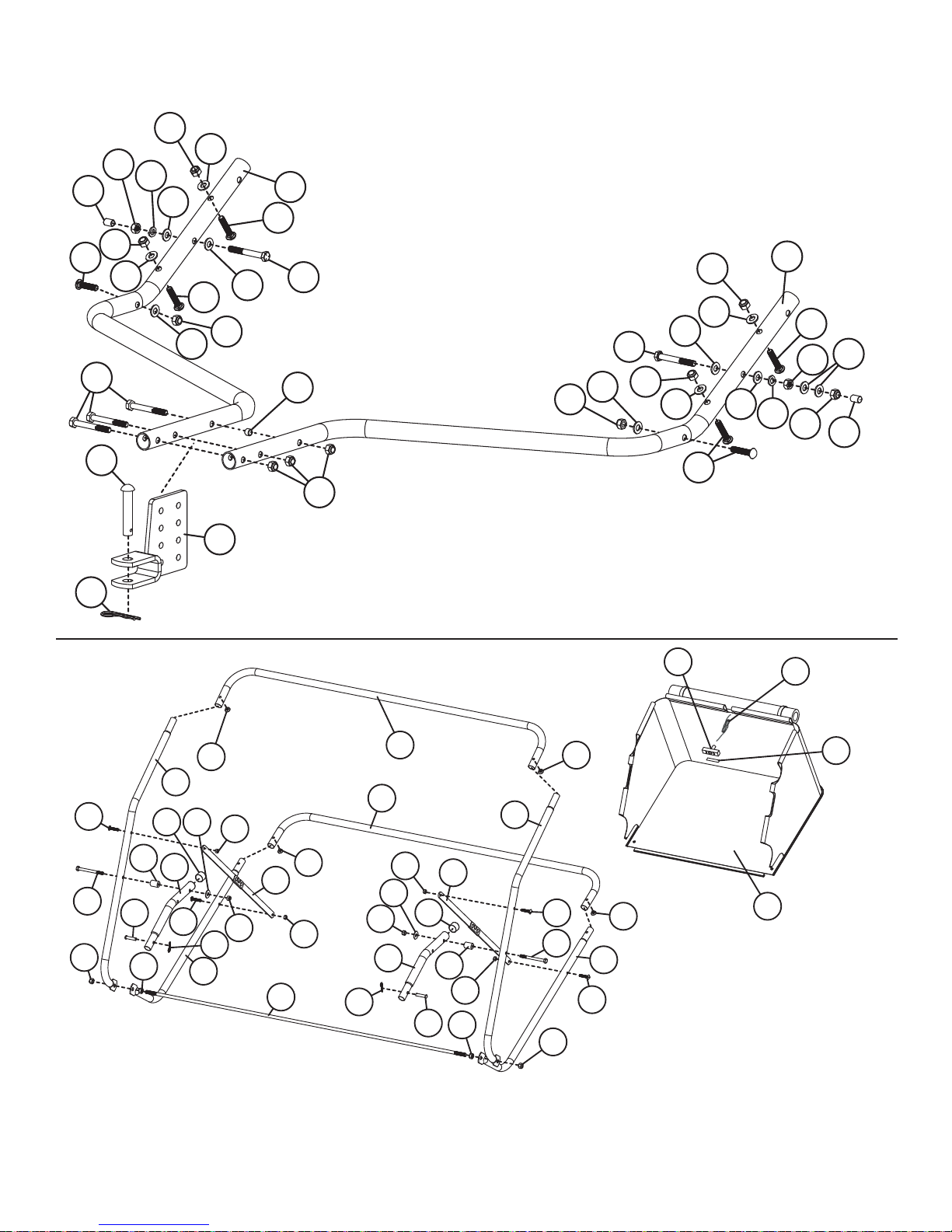
COMPONENT VIEWAND REFERENCE LIST........................................................3-5
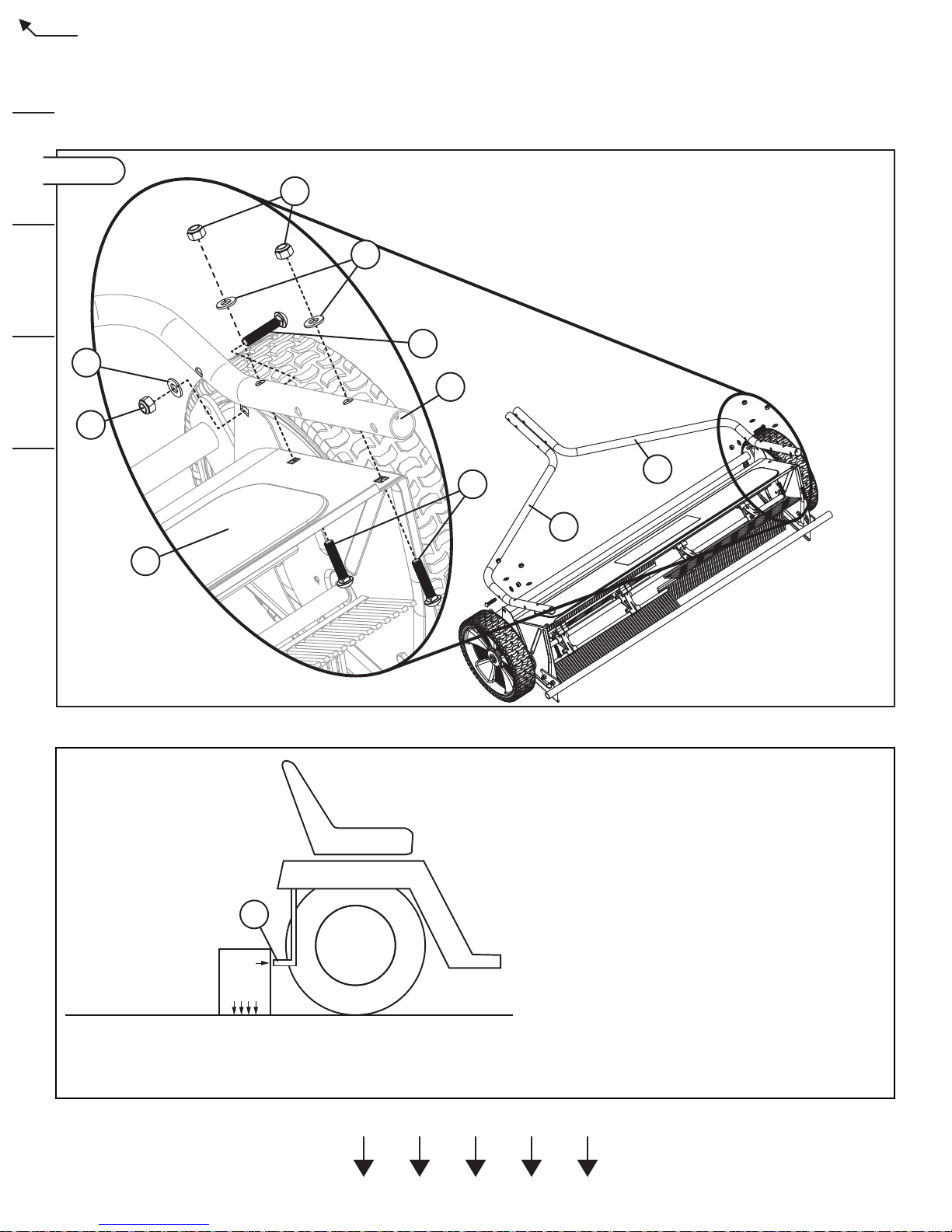
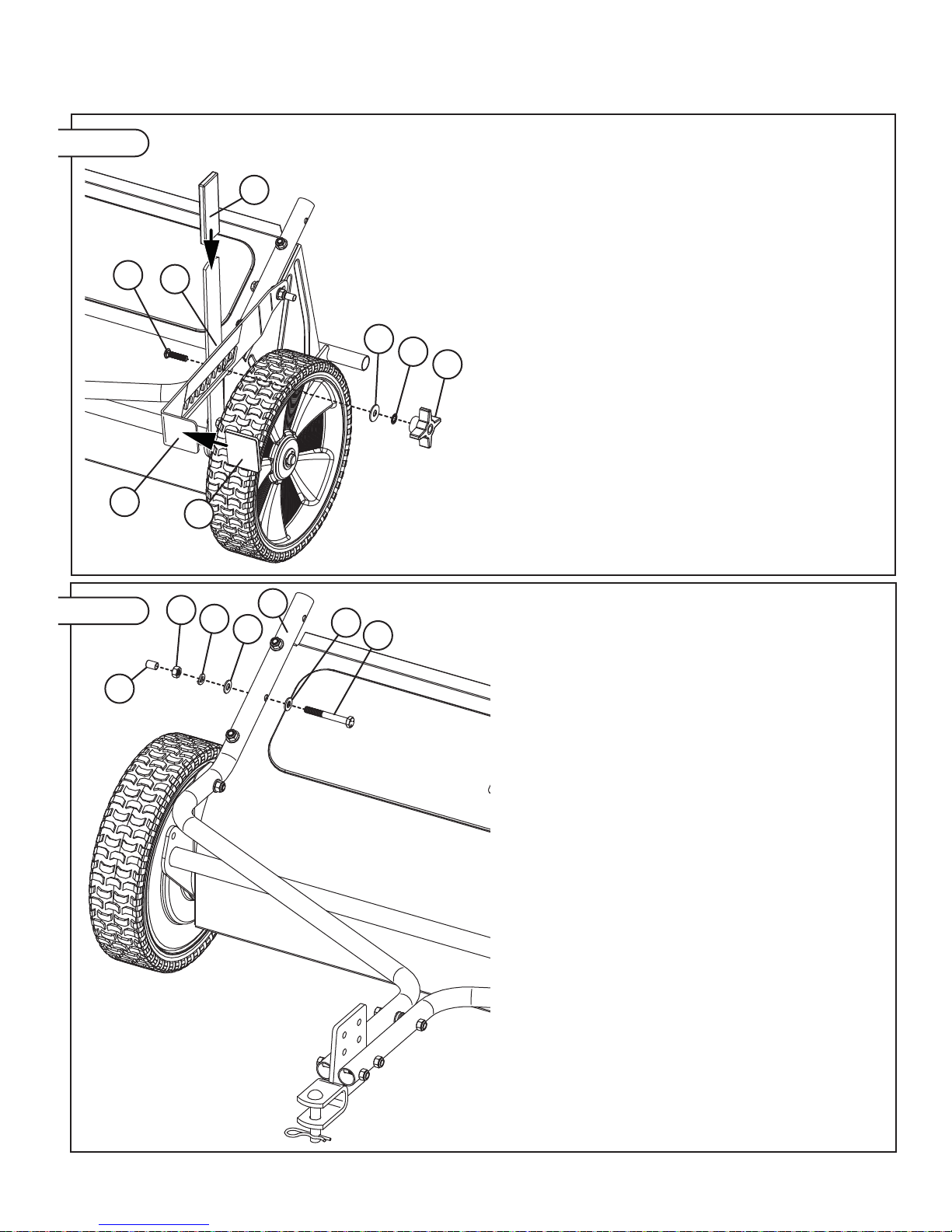
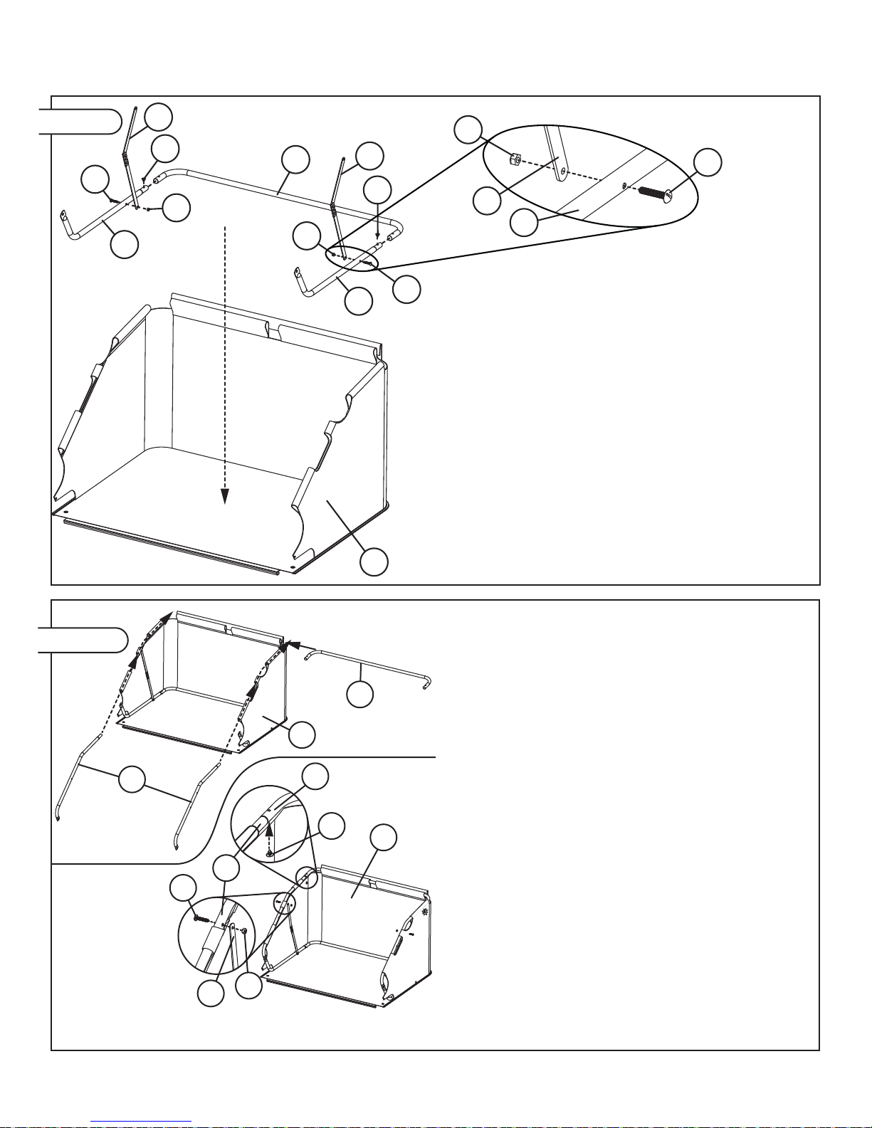
ASSEMBLY ............................................................................................................6-12
SPECIFICATIONS..................................................................................................... 13
OPERATION.........................................................................................................13-16
MAINTENANCE ...................................................................................................17-19
LIMITED WARRANTY...............................................................................................20
SAFETY
========================================================
SAFETY LABELS AND NOTATION
This symbol will help to point out important safety precautions
throughout this manual. It means - ATTENTION! BECOME
ALERT! your safety is involved.
B-7063 (To Scale)
The safety labels shown in this section are placed in important areas on your product
to draw attention to potential safety hazards.
On your product safety labels, the words DANGER, WARNING and CAUTION are
used with the safety-alert symbol. DANGER identifies the most serious hazards.
The operator’s manual also explains any potential safety hazards whenever
necessary in special safety messages that are identified with the word, CAUTION,
and the safety-alert symbol.
GENERAL NOTES (OPERATION)
• Use this attachment for intended purpose only.
• Before you operate any feature of this attachment or towing vehicle,
observe your surroundings and look for bystanders.
• This attachment is intended for use in lawn care and home
applications. Do not tow behind a vehicle on a highway or in any high
speed applications. Do not tow at speeds higher than the maximum
recommended towing speed.
• Towing speed should always be slow enough to maintain control.
Travel slowly over rough terrain. Avoid holes, rocks and roots. Slow
down before turning.
• Do not exceed maximum towing capacity of towing vehicle.
• Do not tow this product behind a motor vehicle such ad a car, truck or
ATV.
• If towing this product behind a ZTR:
1. Confirm the ZTR tow capacity is 200 lbs or more. Do not tow
behind ZTR with a tow capacity less than 200 lbs.
INTRODUCTION AND SAFETY
================================================================================================

1009043-D 3.
COMPONENT VIEW AND REFERENCE LIST
================================================================================================
REF PART NO. DESCRIPTION QTY
1 1008953-10 Lock Arm 1
2 1008958-10 Height Adjustment Handle 1
3 1008960-10 Tow Tube, Right 1
4 1008961-10 Tow Tube, Left 1
5 1008962-10 Hamper Mount 2
6 1008965 5/16" x 1" Spacer 2
7 1009047 Vinyl Bolt Cap 2
8 1009058 Vinyl Grip 1
9 11M1020P 5/16" x 1-1/4" Carriage Bolt 1
10 11M1024P 5/16" x 1-1/2" Carriage Bolt 6
11 20M0820P 1/4" x 1-1/4" Screw 4
12 23037103 Plug 4
13 2M1012P 5/16" x 3/4" Hex Bolt 5
14 2M1044P 5/16" x 2-3/4" Hex Bolt 3
15 2M1056P 5/16" x 3-1/2" Hex Bolt 2
16 30M1000P 5/16" Hex Nut 2
17 30M1200P 3/8" Hex Nut 2
18 40M1000P 5/16" Lock Washer 2
19 45M1111P 5/16" Washer 14
20 B-1673P 1/4" Lock Nut 10
21 B-1674P 5/16" Lock Nut 1
22 B-1675P 3/8" Lock Nut 2
23 B-3861 1/2" X 2-1/2" Hitch Pin 1
24 B-4107 1" Vinyl Cap 2
25 B-4786 5/16" Nylon Lock Nut 16
26 1009205 Grip 1
27 B-4868 5/16" x 2-1/2" Hex Bolt 2
28 B-5650 5/16" Star Lock Washer 1
29 B-983 0.08" Hairpin Cotter 2
30 D-146P 1/8" Hairpin Cotter 1
31 F-782 5/16” Knob 1
32 R-1141-01 Frame Spacer 1
33 R-2303 5/16" X 1-3/8" Clevis Pin 2
34 R-618 Large Washer 3
35 1008997SER Pull Handle 1
36 1009049 Adhesive Hook and Loop 1
37 R-2304 Rope, Pull, Hamper 1
38 1009042-10 Upper Side Tube 2
39 1009044 Spreader Bar Assembly 2
40 1009045 Hamper 1
41 1009046 Adjustment Label 1
42 1008955 Dust Cover 2
43 1008957-10 Lower Pivot 1
44 1008959-01 Wheel Axle 2
45 1008986-10SER Brush Housing 1
46 1008987 Wheel 2
47 1008992-10 Hamper Stop 1
REF PART NO. DESCRIPTION QTY
48 11M0808P 1/4" x 1/2" Carriage Bolt 6
49 50M0624P 3/16” x 1-1/2” Cotter Pin 4
50 B-4768 5/8" Machine Bushing 4
51 B-5924 Brinly Decal 1
52 B-7063 Caution Label 1
53 F-577 5/8" E Ring 6
54 L-1744 Label, Serial No 1
55 R-2205 Brush Section 6
56 R-2259-01 Brush Axle 1
57 R-2261 1/4" x 3/4" Dowel Pin 2
58 R-2262 5/8" Large Flat Washer 2
59 R-2263 5/8" Flat Washer 2
60 R-2281 Brush Holder 4
61 R-2289SER Bearing Retainer 2
62 R-2320 5/8" External Retaining Ring 2
63 R-2321 Screw, Tapping, #12 X 3/8 4
64 R-2485LH LH Drive Pinion 1
65 R-2485RH RH Drive Pinion (Not Shown) 1
66 R-2194-10 Rear Hamper Tube 2
67 R-2195 Hamper Stop Rod 1
68 R-2251-10 Hitch Clevis 1
69 R-2443-10 Lower Side Tube 2
Tools Required for Assembly:
• 1/2” Wrench (2)
• 9/16” Wrench (2)
• 7/16” Wrench (1)
• Flat Tip Screw Driver (1)
• Pliers
• Gloves

1009043-D
4.
3
10
27
19
10
25
14
23
30
68
25
32 25 19 19
25
27 19
25
19 10 19
16
7
25
18
19
10
4
19
19
18
16
7
25
19
10
19
25
66
66
12
20
69 67
25
39
20
11
15
22
22
6
11
33
29
17
17
34
5
24
12
40
12
38
38
12
69
11
20
6
5
25 24
34
20 39
29 33
15
11
37
36
35
Tow Tube Component View
Hamper Frame
and Hamper
Component View
COMPONENT VIEW AND REFERENCE LIST
================================================================================================

1009043-D 5.
26
241
9
13
51 52
45
54 21
1
8
19 47
13
50 53 44 48
50
48
63
53 64
65
62 42 46
49
49
55
60
59
58
20
61
57
56
48
25
20
53
43
34
28
31
Brush Housing
Component View
COMPONENT VIEW AND REFERENCE LIST
================================================================================================
(RH Drive Pinion
Not Shown)

1009043-D
6.
ASSEMBLY
================================================================================================
3
4
25
10
19
25
45
3
10
19
Figure 01 Assemble the Right Tow Bar (3) and Left Tow Tube (4)
to the Brush Housing (45) using the hardware in Panel
01 as shown in Figure 01.
Do not tighten fasteners at this time.
This manual will be referencing panels of the hardware skin pack included with your sweeper. The hardware in Panel
01 is to be used with Figure 01; Panel 02 with Figure 02; etc.
A
Hitch Plate Height
Measurement Park towing vehicle on a level, hard surface and set
parking brake.
Measure from the ground to the bottom of the rear
hitch plate (A).
Note: The scale at the side of this sheet can be used
as a guide for hitch plate heights up to 11 inches.
Record this measurement here: _____________
Round this measurement to the closest
whole number: _____________
For example:
If the hitch plate measurement is 7-1/4” round to 7”.
If the hitch plate measurement is 8-3/4” round to 9”.
If the hitch plate measurement is a half measurement,
round up (example: 7-1/2” rounds to 8”).
11” (Top of Page)
10”
9”
8”
7”
Place this edge on ground.

1009043-D 7.
ASSEMBLY
================================================================================================
68
3
4
32
14
25
68
4
32
14
25
3
7”
8”
9”
10”
11”
12”
13”
14”
Using the rounded measurement from
the previous section, determine the
correct Clevis Assembly (68) mounting
holes from the diagrams directly to the
left
Note that hitch plate heights between
7” and 10” have the Clevis at the
bottom of the bracket and hitch plate
heights between 11” and 14” have the
Clevis at the top of the bracket.
Once the correct Clevis Assembly (68)
mounting holes have been determined,
attach the Clevis Assembly (68)
between the Right and Left Tow Tubes
(3 & 4) using the hardware in Panel 02
as shown in Figure 02.
Do not tighten at this time.
Use the remaining hardware from
Panel 02 and attach the Right and
Left Tow Tubes (3 & 4) at 3rd hole as
shown in Figure 02.
Note: Hitch
clevis at bottom.
3rd
Hole
3rd
Hole
Note: Hitch
clevis at top.
23
30
68
Figure 02
Figure 02
Figure 03
Tighten all hardware used in Figure 01 (6 Carriage
Bolts and Nuts) and Figure 02 (3 Hex Bolts and Nuts).
Using the hardware in Panel 03, attach Hitch Pin (23)
and Hairpin Cotter (30) to the Clevis Assembly.
Height
7”-10”
Height
10”-14”
Hitch
Height Clevis Mount
Holes

1009043-D
8.
21
21
A
B
13
13
43
2
2
ASSEMBLY
================================================================================================
Attach Height Adjustment
Handle (2) to Lower Pivot (43)
side plate using Bolt (13) and
Lock Nut (21) in Panel 04.
Tighten hardware securely.
Note: Large hole (A) in bottom
of the Height Adjustment
Handle (2) must fit over the
Tube (B) extending past the
Lower Pivot (43) side plate.
Note: Wheel assembly not shown for clarity.
Figure 04
16
18
19
4
19
27
7
25
1
19
Figure 05 Using the hardware in Panel 05:
First, assemble the Bolt (27) through the Left Tow Bar
(4) as shown and tighten securely:
• Bolt (27)
• 2 Washers (19)
• Lock Washer (18)
• Nut (16)
Second, assemble the Lock Arm (1) to the bolt as
shown:
• 2 Washers (19)
• Lock Arm (1)
• Nylon Lock Nut (1)
Note: Do not over tighten the Nylon Lock Nut (25).
The Lock Arm (1) should be able to pivot freely after
assembly.
Last, assemble over the end of the Bolt (27):
• Vinyl Bolt Cap (7)
First
First
Second
Second
Last
Last

1009043-D 9.
31
28
34
26
92
18
ASSEMBLY
================================================================================================
Attach Lock Arm (1) to Height Adjustment Handle (2)
using the hardware in Panel 06 as shown in Figure 06.
Note: For proper function of the sweeper height
adjustment mechanism, it is important to assemble the
hardware as shown in Figure 06.
Attach Vinyl Grips (8) and (26) as shown in Figure 06.
Figure 06
27
19
3
19
18
16
7
Figure 07
Assemble the hardware in Panel 07 to the Right Tow
Bar (3) as shown in Figure 07. Tighten securely.

1009043-D
10.
69
69
69
40
66
12 39
39
39
11
20
20
20
11
11
12
Install Lower Side Tubes (69) to Rear Hamper Tube (66) as
shown in Figure 08 and secure with the ¼” Plastic Plugs (12)
in Panel 08.
Assemble one Spreader Bar Assembly (39) to each Lower
Side Tubes (69) using the remaining hardware in Panel 08 as
shown in Figure 08.
The Spreader Bar Assembly (39) should be assembled so
that, when closed, the ‘V’ points toward the open side of the
tubes as shown in Figure 08.
Additionally, it is important that the Round Head Screws (11)
and Lock Nuts (20) are assembled as shown.
Note: Do not over tighten Lock Nut (20). Spreader Bar
Assembly should be able to pivot freely after assembly.
Place the assembled components from above into the
bottom of the Hamper (40).
Figure 08
12 40
66
38
66
40
11
39 20
38
Figure 09
ASSEMBLY
================================================================================================
Assemble the Rear Hamper Tube (66) through the rear loops
sewn into the Hamper (40).
Assemble the Upper Side Tubes (38) through the side
loops sewn into the Hamper (40). Secure them to the Rear
hamper Tube (66) with the ¼” Plastic Plugs (12) in Panel 09.
Assemble each Spreader Bar Assembly (39) to the Upper
Side Tubes (38) using the remaining hardware in Panel 09.
The Spreader Bar Assembly (39) should be connected to the
hole closest to the top bend in the Upper Side Tube (38) as
shown in Figure 09.
Additionally, it is important that the Round Head Screws (11)
and Lock Nuts (20) are assembled as shown.
Note: Do not over tighten Lock Nut (20). Spreader Bar
Assembly should be able to pivot freely after assembly.

1009043-D 11.
67
17
38
22 69 38
40
40
22
69
17
ASSEMBLY
================================================================================================
Using the hardware in Panel 10, assemble one 3/8” Nut
(17) on each end of the Hamper Stop Rod (67) until it is
approximately in the center of the threads.
67 17
Assemble each end of the Hamper Stop Rod (67) through
the holes on the front of the Upper Side Tubes (38) and
Lower Side Tubes (69).
Using the remaining hardware in Panel 10, assemble one
3/8” Lock Nut (22) on each end of Hamper Stop Rod (67).
Tighten the Lock Nut (22) until Hamper Stop Rod (67) is flush
with the top of the Lock Nut (22).
Note: Hold the Hamper Stop Rod (67) with Pliers while
tightening the Lock Nuts (22).
Upper and Lower Side Tubes should be trapped between
the Nut (17) and Lock Nut (22) on the Hamper Stop Rod (67)
but still loose enough to pivot freely. If the tubes do not pivot
freely, loosen Nut (17).
Pull up on bottom of Hamper (40) from “J” Channel and hook
”J” Channel onto Hamper Stop Rod (67).
Snap side flaps to Hamper (40) bottom as shown. Note: Flap
should be on the outside of Lower Side Tubes (69) after
assembly.
Figure 10
Hook
Snap
Snap
34
6
24
15
38
25
5
A
Using the hardware in Panel 11, assemble Hamper Mounts
(5) to Upper Side Tubes (38) as shown in Figure 11. Ensure
that the hole closer to the end of the upper side tube (A) is
used as shown.
Note: Tighten Nylon Lock Nut (25) completely and then
loosen enough so that the Hamper Mount (5) pivots freely.
Assemble Vinyl Caps (24) to Hamper Mounts (5) as shown.
Figure 11
“J” Channel

1009043-D
12.
29 66
37
35
3
37
533
35
36 37
ASSEMBLY
================================================================================================
Figure 12
With the sweeper attached to the towing vehicle (see
‘Attaching the Sweeper’ section of this manual), connect
the Hamper Assembly to the sweeper using the hardware in
Panel 12 (see Figure 12.1).
Tie one end of Hamper Pull Rope (37) to the middle section
of the upper Rear Hamper Tube (66) as shown (see Figure
12.1).
Thread Pull Handle (35) onto opposite end of the Pull Rope
(37) as shown (Figure 12.2).
Extend Pull Rope (37) to the back of the towing vehicle
to an area that will be easily accessible from the towing
vehicle seat. This is the area that the Pull Handle (35) will be
attached.
Allow the Pull Rope (37) to slacken several inches (droop
between the towing vehicle and tied point on the Hamper –
Figure 12.3).
In the area of the Pull Rope (37) determined above, tie 2
knots and pull the knots into the Pull Handle (35) (Figure
12.2).
Clean the area of the towing vehicle that the Pull Handle (35)
will attach to.
Affix the adhesive Hook and Loop (36) tape to the back of
the towing vehicle in the cleaned area.
Cut excess rope if needed.
Important: Pull Rope and Handle can get tangled
in the sweeper brushes if they fall on the ground
in front of the sweeper during operation. After
dumping the hamper, always make sure to fully
secure the Pull Handle to the back of the towing
vehicle using the Hook and Loop tape.
Slacken
Two Knots
To Tractor
To Sweeper
Figure 12.1
Figure 12.2
Figure 12.3

1009043-D 13.
SPECIFICATIONS
================================================================================================
OPERATION
================================================================================================
23
30
68
Attaching the Sweeper
CAUTION: Avoid Injury! Before attaching the Sweeper,
make sure Hamper is empty of all material.
1. Park towing vehicle on a hard, level surface and set parking brake.
2. Align Clevis (68) with towing vehicle hitch plate.
3. Install Hitch Pin (23) through Clevis Assembly (68) and towing vehicle
hitch plate and secure with Hairpin Cotter (30).
Removing the Sweeper
CAUTION: Avoid Injury! Before removing the Sweeper,
make sure Hamper is empty of all material.
1. Confirm Hamper is empty
2. Park towing vehicle on a hard, level surface and set parking brake.
CAUTION: Avoid Injury! Sweeper and sweeper Tow Bar
will shift after removal of Hitch Pin. Use caution when
removing Hitch Pin and moving sweeper.
3. Remove Hairpin Cotter (30) and Hitch Pin (23).
4. Push sweeper away from towing vehicle.
5. Install Hitch Pin (23) through Clevis Assembly (68) and secure with
Hairpin Cotter (30) for storage.
Adjusting to Transport Position
2
3
4
5
6
7
8
910 1
21
31 41
To adjust the Sweeper for Transport:
1. Park towing vehicle on a hard, level surface and set parking brake.
2. Loosen (but do not remove) Knob (31) and adjust Lock Arm (1) to
the 10th position (as indicated on the Adjustment Label (41)). For
adjustment instructions, see the”Adjusting the Brush Height” section.
Determining Maximum Towed Weight
CAUTION: Avoid injury! Excessive towed load can cause
loss of traction and loss of control on slopes. Stopping
distance increases with speed and weight of towed load.
Total towed weight must not exceed combined weight of
towing vehicle, ballast and operator.
The following maximum loaded weight is the average weight of the
sweeper plus the weight loaded in the hamper.
Model Weight Capacity
STH-420BH 75 lbs empty
195 lbs with wet grass
Caution: Avoid Injury! If additional weight is required
when towing, add weight at or forward of the rear wheels.
Adding weight behind the rear wheels can affect vehicle
steering.
Refer to your towing vehicle manual for information
regarding addition of weight.
Towing capacity will vary with the weight of the towing vehicle and
operator. Add the weight of your machine to operator weight to find the
maximum capacity for towing.
Maximum Towing Speed: 5 mph
Hamper Capacity: 20 cu. Ft.
Maximum Hamper Weight: 120 lbs
Empty Weight: 75 lbs
Maximum Towed Weight: 195 lbs

1009043-D
14.
It is recommended to set the brush height at a higher number than is
anticipated to be needed and perform a short sweeping test on the lawn.
Reduce brush height one setting at a time until the desired sweeping
performance is achieved.
For reference:
Lock Arm
Number Approximate Brush
Height Sweeping Conditions
1 to 3 1/4” to 1” (6.5mm to
25mm) Extremely low-cut grass and light
material.
3 to 6 1” to 2” (25mm to
50mm) Mowed lawns under normal
conditions or light leaves
6 to 10 2” to 3-1/4” (50mm to
82mm) High grass, heavy leaves or heavy
grass clippings
Note: Settings 1 to 3 should be used only on very short grass heights
and light material.
Leveling the Hamper
47
25
Adjust
Not Level
After correct brush height is determined, it may be necessary to adjust
the Hamper Stop (47) so that the Hamper assembly remains clear of the
ground.
To adjust the Hamper Stop (47):
1. Loosen (but do not remove) the two Nuts (25) securing each side of
the Hamper Stop (47).
The rear mounting holes are slotted, allowing the Hamper Stop (47)
to be pivoted up or down for adjustment.
2. Move the Hamper Stop (47) up or down to adjust the resting position
of the Hamper assembly so that it is approximately level.
3. Tighten Nuts (25) on each side to secure the Hamper Stop (47) in
position.
If correct Hamper assembly adjustment is not possible, the Clevis
Assembly (68) may need to be readjusted so that the Hamper assembly
has adequate clearance to the ground.
The sweeper Tow Tubes should be parallel with the ground (or angled
slightly forward) when the sweeper is connected to the towing vehicle. If
the Tow Tubes are angled rearward, adjust the Tow Tube mounting holes
on the Clevis Assembly (68) lower. This will angle the Tow Tubes forward
and raise the Hamper assembly.
Example:
If towing vehicle weighs: 400 lbs
Add operator weight: 200 lbs
Combined weight equals: 600 lbs
To maintain stability in this example, you cannot safely tow more than 600
lbs without first adding ballast (additional weight) to the towing vehicle.
Adjusting the Brush Height
Important: Setting the brush height too low for sweeping
conditions causes excessive wheel skipping and slipping. For
best performance, adjust brush height as high as possible for the
material and conditions.
Normal lawn sweeping is accomplished when the brushes sweep at the
same height as the mower cutting height.
To adjust brush height:
1. Park towing vehicle on a level, hard surface and set parking brake.
2. Turn towing vehicle off.
3. Measure the height of the of the mower blade.
4. Attach sweeper to the towing vehicle hitch plate as previously
described.
5. Adjust Lock Arm (1) into a slot that allows the brushes to sweep at
the same height as the mower blade:
a) Loosen (do not remove) Knob (31).
b) Apply light downward pressure to Height Adjustment Handle (2)
while lifting up on Lock Arm (1).
c) Move Height Adjustment Handle (2) to the desired position and
lower Lock Arm (1).
d) Tighten Knob (31) firmly.
23
4
5
6
7
8
910 1
2
1
31
6. Check to be sure that the Hamper is not dragging on the ground and
adjust as necessary (see ‘Leveling the Hamper’ section).
Higher numbers on the Lock Arm (1) decal indicate higher brush heights.
2345678910 1
(41) 1009046 (Not to scale)
For best performance, brush height should be set to the highest possible
number while still adequately sweeping the lawn.
OPERATION
================================================================================================

1009043-D 15.
OPERATION
================================================================================================
Operating Speed
The operating ground speed of the sweeper has a direct effect on how
material is thrown into the hamper. Material will be thrown farther toward
the back of the hamper as ground speed increases.
Operation speed will depend on the condition of the lawn and material
being swept. Operate the sweeper at a ground speed that will throw
material to the back of the hamper. Under normal conditions 3 mph
(approximately the speed of a brisk walk or 40 feet in 9 seconds) works
best.
Maximum operating speed is 5 mph.
Emptying the Hamper
Caution: Avoid Injury! Make sure area is clear of
bystanders, especially children, before backing up.
Before dumping material from the Hamper: Park towing vehicle and set
parking brake (see owners manual).
Important: Avoid overfilling the Hamper, especially when sweeping
freshly mowed grass or other moist material. Heavy loads will be
more difficult to dump.
To empty Hamper:
1. Tow the sweeper to a location the material should be dumped.
2. Stop towing vehicle and set parking brake.
3. Pull Handle (35) and Rope (37) to tilt hamper forward/upward,
allowing material to exit the opening at the front of the Hamper.
4. Replace Pull Handle (35) to Hook and Loop (36) fixed to the
towing vehicle.
Important: After dump operation is complete, confirm Pull Handle
(35) is fully secured to the back of the towing vehicle. Pull Rope
and Handle can get tangled in the sweeper brushes if they fall on
the ground in front of the sweeper during operation.
Using the Wind Screen
The Hamper Wind Screen can be configured in three positions based on
conditions and preference.
Position 1 – Wind Screen Fully Open
Roll the Wind Screen to the top of the Hamper. Use the hook and loop
straps to hang the Wind Screen from the back of the Hamper.
Can be used when there is little to no wind; Operating speed should be
slower to ensure material is not thrown over the Hamper.
Roll Attach
Attach
Position 2 – Wind Screen Half Closed
Unroll the Wind Screen. Attach the Wind Screen to the Hamper Upper
Side Tubes using the hook and loop straps in the middle of the Wind
Screen. Fold the Wind Screen back and attach the elastic straps to the
hook and loop on the back of the Hamper.
Can be used in medium wind to prevent material from blowing out of
Hamper; Operating speed should be slower to ensure material is not
thrown over the Hamper or Wind Screen.
Attach
Attach Attach
Attach
Position 3 – Wind Screen Fully Closed
Unroll the Wind Screen. Attach the Wind Screen to the Hamper Upper
Side Tubes using the hook and loop straps in the middle of the Wind
Screen. Attach the Wind Screen to the Brush Housing by extending the
elastic straps over the long bolts extending past the Tow Tubes.
Can be used in higher winds to prevent material from blowing out of
Hamper; Operating speed can be higher (maximum operating speed is 5
mph)
Note: It is difficult to see how much material is in the Hamper when the
Wind Screen is fully closed. Empty the Hamper frequently to ensure it
does not become overfilled.
Attach
Attach
Attach
Attach

1009043-D
16.
Storage
The sweeper can be tipped upright and stored against a wall using a
minimum of space:
1. Remove any loose material from hamper, brushes, brush housing
and drive assembly. The sweeper should be clean and dry before
configuring for storage.
2. Remove small hairpin cotters and clevis pins that are securing
the hamper assembly to the brush housing. Remove the hamper
assembly. Replace the clevis pins and hairpin cotters in the hamper
mount tubes for storage.
3. Collapse the hamper by unlocking the spreader bar assembly (push
forward). Orientate the collapsed hamper so that the rear hamper
tubes are up. Put rope and pull handle into the pocket created
between the rear hamper tubes.
4. On sweeper, adjust brush height to position 10 on the LockArm
5. Roll sweeper to desired storage area. Lift clevis assembly vertically
so that the sweeper is standing upright on the hamper mount tubes
and hamper stop bar. Move close to the wall so that the top of the
brushing housing faces the wall (brushes face out).
6. Position collapsed hamper between sweeper and wall and hang on
the clevis assembly, from the middle of the rear hamper tube.
OPERATION
================================================================================================
Frequently Asked Questions
Sweeper does not pick up:
1. The brush height adjustment is set too low. The sweeper is not a
dethatcher and cannot pull thatch, embedded needles or embedded
leaves from deep in the grass. The brush height should be adjusted
to the height of the mower deck blades.
2. The brush height adjustment is set too high. Lower the brush height
one notch at a time on the lock arm until the desired performance is
achieved.
3. There is a problem with the brush drive system. See the ‘Sweeper
Wheels’ section below.
Grass or material goes over the top of the hamper:
1. Forward speed is too fast. Slow towing vehicle down. Best speed is 3
mph or less (3 mph = 40 feet in 9 seconds).
2. The wind screen can be used to remedy this concern. See the ‘Using
the Wind Screen’ information in the ‘OPERATION’ section of this
manual.
Sweeper Wheels (not moving, skipping or locking up):
1. The wheels are geared to turn the sweeper brushes. If the sweeper
wheels are not moving, skipping or locking up; it is possible that the
brush height is set too low. Measure the cut height of the mower.
Adjust the brush height to sweep at the same level as the cut height.
2. The drive dowel(s) located inside the small metal drive pinion gear(s)
are sticking. Remove, clean and lubricate the dowel(s), drive pinion
gear(s) and brush axle as shown in the ‘Preventative Maintenance’
section of this manual.
3. The drive pinion gear(s) are worn and because of this it locks the
drive dowel(s). Remove, inspect and replace the drive pinion gear(s)
and drives dowel(s) as needed. See ‘Preventative Maintenance’
section of this manual.
4. The drive pinion gears, when re-installed, were installed backwards.
For example: the right side gear was installed on the left side of the
sweeper. See the ‘Preventative Maintenance’ section of this manual
for proper drive pinion gear assembly.
Hamper drags on the ground:
1. The tow bars are not level with the ground when attached to the
towing vehicle. Remove the clevis assembly and reinstall in a
different set of mounting holes. The clevis can be turned over to get
additional adjustment. See assembly ‘Figure 02’ and ‘Leveling the
Hamper’ sections of this manual.
Hamper orientation is too high:
1. Hamper mount tubes are assembled upside down. See Figure 11
and confirm orientation of hamper mount tubes.

1009043-D 17.
MAINTENANCE
================================================================================================
Preventative Maintenance:
General
1. Do not allow material to remain in the Hamper for extended periods
of time. Clean the Hamper using a water hose and allow it to dry
completely before storage.
2. Check all moving parts for wear and freedom of movement.
3. Check all fasteners for tightness and retighten as required.
4. Inspect for rust on painted surfaces. Sand lightly and touch up
damaged areas with enamel paint.
5. Routine lubrication of the Dowel Pin and Drive Pinion is required.
At a minimum it is recommended to do this twice per year: in the
fall before storage, and again in the spring before the first use.
Follow the procedure outlined below in the ‘Wheel and Drive Gear’
maintenance section.
6. Check the Drive Pinions and Dowel Pins for wear and replace as
needed. These are considered normal wear parts. Contact the
Customer Service Department to purchase replacement parts.
7. Lubricate the Wheel Axles annually following the procedure outlined
in the Maintenance section.
Brush Section Replacement
Note: This procedure will show an example for right side Brush Section
(55) replacement. Reverse pull directions for left side Brush Section
replacement.
Tools Needed:
Safety Glasses, Work Gloves
Rubber Mallet
45 55
60 60
1. Stand the sweeper in storage position on a clean flat surface such as
garage floor or sidewalk (do not hang hamper from clevis assembly).
2. Inspect the Brush Section and notice which side has the short bristles
(these will be located near the metal rail of the Brush Section). It
is important that the new Brush Section is assembled in the same
orientation.
3. Using the rubber mallet, tap the metal rail of the Brush Section (55)
to the left. This will loosen the Brush Section from the Brush Holders
(60).
4. Wearing work gloves, firmly grasp the Brush Section (55) between
the Brush Holders (60) and pull to the right. Continue to pull the
Brush Section (55) to the right until it is free from both Brush Holders
(60).
Note: It may be necessary to have a second person hold the sweeper
in place while pulling the Brush Section (55) free.
5. Align the metal rail of the new Brush Section (55) with groove on
inside Brush Holder (60). Note: Orientation of Brush Section (55)
short bristles must be as observed in Step 2.
6. Tap Brush Section (55) into Brush Holder (60) using the rubber
mallet.
7. Continue to tap Brush Section (55) into the first Brush Holder (60). Be
sure to align the metal rail of the Brush Section (55) with the groove
on the second Brush Holder (60).
8. Continue to tap Brush Section (55) into Brush Holders (60) until the
metal rail aligns with the remaining two Brush Sections (55) or about
1/2 to 3/4 inch from Brush Housing (45) side panel.
9. Turn brush assembly and confirm there is no contact between the
metal rail of the Brush Section (55) and the Brush Housing (45) side
panel. If there is contact, pull the Brush Section (55) to the right until
brush assembly spins freely.
10. Repeat as need for the remaining Brush Sections (55).
Wheel and Drive Gear
Important: Safety glasses should be worn while performing
maintenance operations on the sweeper. Solvent proof
gloves (rubber or latex), should be worn when using any
cleaning or lubrication products.
Important: Drive Pinions (64 & 65) are Right and Left hand
specific as indicated on the bottom surface of the part. Left
hand Drive Pinion (64) is indicated with ‘L’ and right hand
Drive Pinion is indicated with ‘R’.
Refer to the illustration below showing the right and left
side of sweeper.
Right
Left
Tools Needed:
• Safety Glasses, Rubber or Latex Gloves
• Medium Flat Tip Screwdriver
• Retaining Ring Pliers (External)
• 7/16 inch Wrench
• 1/4 inch Wrench

1009043-D
18.
MAINTENANCE
================================================================================================
53 50 46
42
44
45
62 59
65
57
58 56
61
63
Wheel and Drive Gear
Disassembly and Inspection
1. Stand the sweeper in storage position on a clean flat surface such as garage floor or sidewalk (do not hang hamper from clevis assembly)
2. Using a medium flat tip screwdriver, remove E-Ring (53)
3. Remove Machine Bushing (50) and Wheel (46)
4. Inspect Wheel gear and Wheel Axle hole for damage and wear
5. Inspect Wheel Axle (44) for damage and wear. Note: Wheel Axle (44) can be removed from the inside of the brush housing.
6. Clean any dirt or debris from the inside of the Wheel (46) and Dust Cover (42)
7. Confirm the Tapping Screws (63) holding the dust cover in place are not loose. Warning: Do not over tighten!
8. Remove Retaining Ring (62) from recess in drive pinion gear. This example shows the RH Drive Pinion or (65).
9. Remove Flat Washer (59) and Drive Pinion (65). Note: Cup one hand under the Drive Pinion during removal as the Dowel Pin (57) may fall free.
10. Inspect and clean the inside of the Drive Pinion. Note that the bottom of this gear has ‘R’ emboss into it, indicating the RH Drive Pinion.
11. Remove the Dowel Pin (57) from the Brush Axle (56) (if it has not already fallen free).
12. Inspect and clean the Dowel Pin
13. Inspect and clean the Dowel Pin hole on the brush axle. A small rag or paper towel can be used to clean the inside of the hole.
14. Remove the Large Flat Washer (58). Inspect and clean the washer and the area around the Brush Axle (56).
If Bearing Retainer (61) replacement is needed, continue with Step 15.
If Bearing Retainer (61) does not need replacement, continue at ‘Assembly and Lubrication’ section.
15. If Bearing Retainer (61) replacement is needed, remove Tapping Screws (63) and Dust Cover (42).
16. Remove E-Ring (53) using a medium flat tip screwdriver.
17. Remove the Lock Nuts (20) securing the Bearing Retainer. Note: Do not let the Carriage Bolts (48) fall out of the Lower Pivot (43) side plate.
18. Remove Bearing Retainer (61)

1009043-D 19.
42
63
63 20
53
20
61
45
48
48
56 43
Dust Cover and Bearing
Retainer
MAINTENANCE
================================================================================================
Assembly and Lubrication
If Bearing Retainer (61) was removed, continue with Step 1. If Bearing Retainer (61) was not removed, begin at Step 5.
1. Insert new Bearing Retainer (61) onto Brush Axle (56). The Bearing Retainer (61) should fit flush on the Lower Pivot (43) side plate with the Bearing
Retainer (61) flange fitting inside the hole in the Lower Pivot (43) side plate and hole in the Brush Housing (45).
Note: Take care when assembling the new Bearing Retainer (61) so that Carriage Bolts (48) remain in Lower Pivot (43) side plate.
2. Assemble the 3 Lock Nuts (20) securing the Bearing Retainer (61). Tighten all three Lock Nuts (20).
3. Snap E-Ring (53) into place on the Brush Axle (56). Note: Be sure E-Ring is fully engaged with groove on BrushAxle (56).
4. Assemble the Dust Cover (42) to the Lower Pivot (43) side plate using the Tapping Screws (63). Warning: Do not over tighten!
5. Apply WD40, 3 in 1 oil or other similar light lubricant directly to the inside of the Dowel Pin hole.
6. Replace the Large Flat Washer (58) onto the BrushAxle (56) until it touches the Bearing Retainer (61).
7. Turn the BrushAxle (56) so that the Dowel Pin hole is horizontal with the ground.
8. Apply WD40, 3 in 1 oil or other similar light lubricant to the Dowel Pin (57) and insert into the Dowel Pin hole on the Brush Axle (56). Note: center
the Dowel Pin (57) so that an even amount is showing on both sides of the Brush Axle (56).
9. Insert the Drive Pinion (65) onto Brush Axle until it touches the Large Flat Washer (58). Note: Dowel Pin (57) will now be inside the Drive Pinion
(65).
10. Insert Flat Washer (59) over the Brush Axle (56) and into the recess on the Drive Pinion (65).
11. Assemble the Retaining Ring (62) onto the Brush Axle (56). Be sure that the Retaining Ring (62) is fully engaged with the groove on the Brush Axle
(56).
12. If removed, replace the Wheel Axle (44) from the inside of the Brush Housing (45).
13. Apply a light coating of general purpose axle oil/grease to the Wheel Axle (44).
14. While holding the Wheel Axle (44) on the inside of the Brush Housing (45), insert the Wheel (46) onto the Wheel Axle (44). Note: wheel may have to
be turned slightly to engage Wheel gear with Drive Pinion gear.
15. Replace the Machine Bushing (50) and snap E-Ring (53) into place on Wheel Axle (44). Note: Be sure E-Ring is fully engaged with groove on
Wheel Axle (44).
Repeat for left side Wheel and Drive Gear service.

1009043-D
20.
The limited warranty set forth below is given by Brinly-Hardy
Company with respect to new merchandise purchased and used
in the United States, its possessions and territories.
Brinly-Hardy Company warrants the products listed below against
defects in material and workmanship, and will at its option, repair
or replace, free of charge, any part found to be defective in
materials or workmanship. This limited warranty shall only apply
if this product has been assembled, operated, and maintained
in accordance with the Operator’s manual furnished with the
product, and has not been subject to misuse, abuse, commercial
use, neglect, accident, improper maintenance, alteration,
vandalism, theft, fire, water, or damage because of other peril or
natural disaster.
Normal Wear Parts or components thereof are subject to separate
terms as follows: All normal wear parts or component failures will
be covered on the product for a period of 90 days.
Parts found to be defective within the warranty period will be
replaced at our expense. Our obligation under this warranty is
expressly limited to the replacement or repair, at our option, of
parts found to be defective in material and workmanship.
HOW TO OBTAIN SERVICE: Warranty parts replacements
are available, ONLY WITH PROOF OF PURCHASE, through our
Customer Service Department. Call 877-728-8224.
This limited warranty does not provide coverage in the following
cases:
a) Routine maintenance items such as lubricants and filters.
b) Normal deterioration of the exterior finish due to use or
exposure.
c) Transportation and/or labor charges.
d) The warranty does not include commercial and/or rental
use.
No implied warranty, including any implied warranty of
merchantability of fitness for a particular purpose, applies
after the applicable period of express written warranty above
as to the part as identified below. No other express warranty
whether written or oral, except as mentioned above, given
by any person or entity, including a dealer or retailer, with
respect to any product, shall bind Brinly-Hardy Co. During
the period of the warranty, the exclusive remedy is repair or
replacement of the product as set forth above.
The provisions as set forth in this warranty provide the sole
and exclusive remedy arising from the sale. Brinly-Hardy
Co. shall not be liable for incidental or consequential loss
Pull Behind Accessorie
s
MANUFACTURER’S LIMITED WARRANT
Y
FOR
or damage including, without limitation, expenses incurred
for substitute or replacement lawn care services or for rental
expenses to temporarily replace a warranted product.
Some states do not allow the exclusion or limitation of incidental
or consequential damages, or limitations on how long an implied
warranty lasts, so the above exclusions or limitations may not
apply to you.
During the warranty period, the exclusive remedy is replacement
of the part. In no event shall recovery of any kind be greater that
the amount of the purchase price of the product sold. Alteration
of safety features of the product shall void this warranty. You
assume the risk and liability for loss, damage, or injury to you and
your property and/or to others and their property arising out of the
misuse or inability to use this product.
This limited warranty shall not extend to anyone other than the
original purchaser or to the person for whom it was purchased as
a gift.
HOW STATE LAW RELATES TO THIS WARRANTY: This
limited warranty gives you specific legal rights, and you may also
have other rights which vary from state to state.
IMPORTANT: The Warranty period stated below begins with
the PROOF OF PURCHASE. Without the proof of purchase, the
Warranty period begins from the date of manufacture determined
by the serial number manufacturing date.
WARRANTY PERIOD:
The warranty period for the product shown in this manual is as
follows: Steel Frame Parts: 2 Years. Tires, Wheels and Drive are
normal wear parts - 90 days.
Brinly-HardyCompany,3230IndustrialParkway,Jeffersonville, IN47130 (877) 728-8224
Table of contents