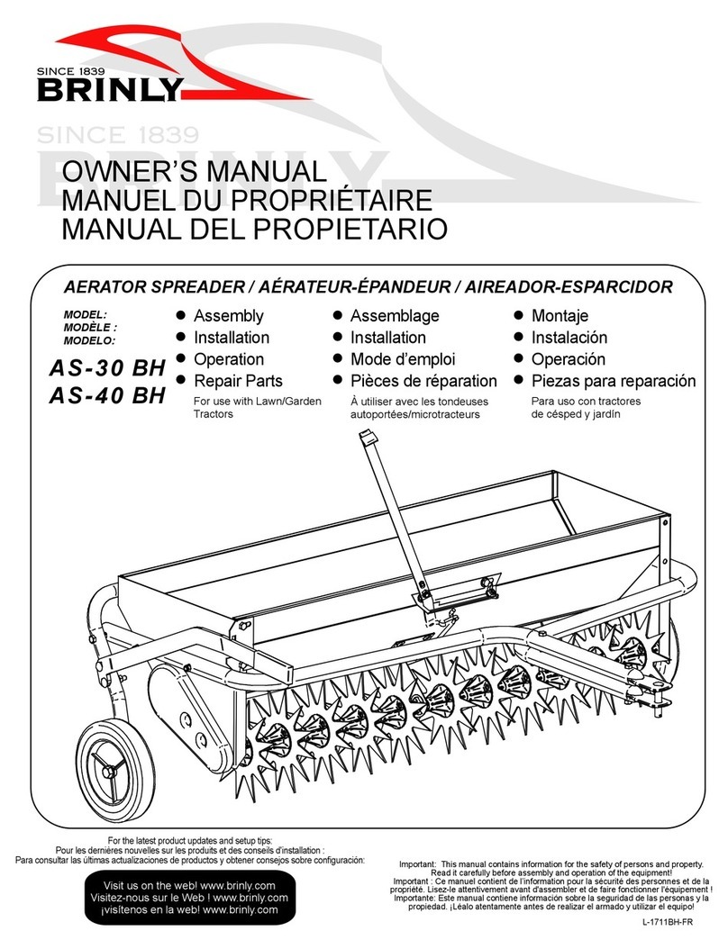
Brinly-Hardy Spyker Spreaders ROS 6 User manual

Spyker Spreaders / A Brinly-Hardy Co. 1020313-A
ROS 6
Model S100-12020 Ride-On Spreader
Spyker Spreaders
Contact Us at 800.972.6130
!!IMPORTANT
This manual contains information for the safety of persons and property.
Read it carefully before assembly and operation of the equipment!
OPERATOR'S MANUAL

English Manual 21020313-A
El manual español
comienza a mitad de
este folleto.
Table of Contents + Safety
TABLE OF CONTENTS
Operate Safely ................. 2
Safety Labels ................ 2-3
Safety Precautions ............ 4-5
Specications .................. 5
Assembly ................... 6-7
Operating Instructions ......... 7-9
Maintenance .............. 10-12
Settings .................. 13-15
Chart - Dial Settings ......... 15
Chart - Grass Seed Spread .... 15
Warranty .................... 16
Safety Labels
1008867 (Not to scale)
WARNING
Do not step, stand or sit.
CAUTION: The Spyker S100-12011 Ride-on
Spreader should only be operated and
maintained by thoroughly trained individuals.
The machines could cause serious injury to
anyone who misuses them or does not
understand their operation. All operators and
maintenance personnel are urged to read this
entire manual for their personal safety.
OPERATE SAFELY
UNDERSTANDING THE MACHINE SAFETY LABELS:
The machine safety labels shown in this section are placed
in important areas on your machine to draw attention to
potential safety hazards.
On your machine safety labels, the words DANGER,
WARNING, and CAUTION are used with this safety-alert
symbol. DANGER identies the most serious hazards.
The operator’s manual also explains any potential safety hazards
whenever necessary in special safety messages that are
identied with the word CAUTION and the safety-alert symbol.
Safety Alert Symbol
DO NOT STEP,
STAND, OR SIT.
WARNING

English Manual 31020313-A
Safety Labels
CAUTION
Serious bodily injury may result from
failure to follow safe operator procedure.
• Read the operator’s manual before operating
this machine.
• Clear area of debris.
• Do not remove or disable shields, guards or
safety devices.
• Always chock the wheels or engage the
parking brake when transporting the
machine or when parking on a grade.
• Stop engine, disconnect spark plug, set
parking brake before adjusting or servicing.
• Keep people and pets a safe distance away
from machine.
• Do not add fuel while engine is warm or
running.
• Use caution on slopes.
• Before leaving the operator’s position, wait
for all movement to stop.
• Do not allow operation of the machine by
untrained personnel.
FOR FIRST-TIME OPERATORS
• Start o in a at, open area.
• Keep bystanders away.
• Set throttle at a low speed.
• Practice maneuvering.
(Forward, Reverse, Left & Right).
1009018 (Not to scale)
ACCUWAY®
SPREAD CALIBRATION
OFF
ADJUSTMENT
OFF
SIDE
DEFLECTOR
DOWN
UP
HOPPER
SHUT-OFF
OPEN
CLOSED
Serious bodily injury may
result from failure to follow
safe operator procedure.
• Read the operator’s manual before
operating this machine.
• Clear area of debris.
• Do not remove or disable shields, guards,
or safety devices.
• Always chock the wheel or engage the
parking brake when transporting the
machine or when parking on a grade.
• Stop engine, disconnect spark plug, set
parking brake before adjusting or servicing.
• Keep people and pets a safe distance away
from machine.
• Do not add fuel while engine is warm or
running.
• Use caution on slopes.
• Before leaving the operator’s position, wait
for all movement to stop.
• Do not allow operation of the machine by
untrained personel.
CAUTION
FOR FIRST-TIME OPERATORS
• START OFF IN A FLAT, OPEN AREA.
• KEEP BYSTANDERS AWAY
• SET THROTTLE AT A LOW SPEED.
• PRACTICE MANEUVERING,
(FORWARD, REVERSE, LEFT, RIGHT)
1009121 (Not to scale)
CAUTION
To Avoid Injury, Follow Start Procedure:
1. Engage Parking Brake.
2. Move Free Wheel Lever to BYPASS.
3. Ensure Ground Speed Control Levers are
in neutral.
4. Turn ON Engine Switch.
5. Start Engine.
CAUTION
To Avoid Injury, Follow Start
Procedure:
1. Engage Parking Brake.
2. Move Free Wheel Lever to BYPASS.
3. Ensure Ground Speed Control Levers
are in neutral.
4. Turn ON Engine Switch.
5. Start Engine.
1009121
ATENCIÓN
Para evitar sufrir lesiones, respete
el procedimiento de inicio:
1. Coloque el freno de mano.
2. Mueva la palanca libre de la rueda a
BYPASS (Derivación).
3. Asegúrese de que las palancas de
control de velocidad sobre el suelo
estén en punto muerto.
4. Coloque el interruptor del motor en ON
(Encendido).
5. Arranque el motor.

English Manual 41020313-A
Safety Precautions
A. GENERAL:
1. Read this Operator’s Manual completely before
starting the spreader. If the operator(s) or
mechanic(s) cannot read English it is the owner’s
responsibility to explain this material to them.
2. Retain Operator’s Manual in a safe place for future
reference.
3. Become familiar with the safe operation of the
equipment, operator controls, and safety signs.
4. All operators and mechanics should be trained.
The owner is responsible for training the users.
5. Never let children or untrained people operate or
service the equipment. Local regulations may
restrict the age of the operator.
6. The owner/user can prevent and is responsible for
accidents or injuries occurring to themselves, other
people or property.
7. Do not remove any shields, guards, decals or
safety devices. If a shield, guard, decal or safety
device is damaged or does not function, repair or
replace it before operating the spreader.
8. Always wear safety glasses, long pants and safety
shoes when operating or maintaining this spreader.
Do not wear loose-tting clothing.
9. Never run the engine indoors without adequate
ventilation. Exhaust fumes are deadly.
10. Never run an engine in an enclosed area.
11. Do not change the engine governor setting or over-
speed the engine.
B. RELATED TO FUEL:
1. Use extra care when handling gasoline and
other fuels. They are flammable and vapors are
explosive.
2. Never refuel or drain the machine indoors.
3. Do not smoke or permit others to smoke while
handling gasoline.
4. Always use approved containers for gasoline.
5. Always shut o the engine and permit it to cool
before removing the cap of the fuel tank.
6. If the fuel container spout will not t inside the fuel
tank opening, use a funnel.
7. When lling the fuel tank, stop when the gasoline
reaches one inch from the top. This space must be
left for expansion. Do not overll.
8. Wipe up any spilled gasoline.
C. WHEN OPER ATING:
1. Keep adults, children and pets away from the area
to be spread.
2. Always check the area to be spread and remove
debris and other objects prior to spreading.
3. Spread only in daylight.
4. Watch for holes, sprinkler heads and other hidden
hazards.
5. Reduce speed when making turns.
6. Use extra care when operating the machine with
an empty hopper. This can aect the stability of the
machine. Do not use on steep slopes.
7. DO NOT operate machine on steep slopes. Slow
down and use extra caution on hillsides. Go
laterally or diagonally across the slope, not up and
down the slope. Turf conditions can aect the
machine’s stability. Use caution while operating
near drop-o’s.
8. Always have proper footing on slopes and hill sides
and never operate when conditions are slippery.
Be very careful on wet grass.
9. Always keep both hands on the handles.
10. The ground speed control levers and direction
control handle are designed for your safety. Do not
modify them or operate the machine if they are
damaged.
11. Use care when approaching blind corners, shrubs,
trees, or other objects that may obscure vision.
SOME OF THE FOLLOWING PRECAUTIONS
ARE BASED ON ANSI B71.4-2004:

English Manual 51020313-A
Safety Precautions
12. Look behind and down before backing up to be
sure of a clear path.
13. Never carry passengers.
14. Use care when loading or unloading the machine
into a trailer or truck.
15. Be careful when crossing gravel paths or roadways.
16. Always have your feet and hands clear of the
controls when starting the engine.
17. Always park the spreader and start the engine on
a level surface with the ground speed control
levers in neutral, the free wheel lever in bypass,
and the park brake engaged.
18. Never leave the spreader unattended without
placing the spreader on level ground, placing
ground speed control levers in neutral, engaging
the park brake, shutting o the engine and closing
the fuel shuto valve.
19. To avoid serious burns, do not touch the engine or
muer while the engine is running or until it has
cooled for at least 30 minutes after it has been shut
o.
20. If you hit a solid object while spreading, place the
ground speed control levers in neutral, engage the
park brake and stop the engine. Disconnect the
spark plug wire and inspect for damage. Repair
any damage.
21. Always disconnect the spark plug wire to prevent
the engine from accidentally starting before
performing any maintenance on this spreader.
22. Keep the machine and especially the engine/
transmission area clean and free of grease, grass
and leaves to reduce the potential for overheating
and re.
23. Do not exceed hopper capacity listed in
Specifications Section.
24. To prevent injury from hand, never place hands
into hopper while fan is spinning.
SOME OF THE FOLLOWING PRECAUTIONS
ARE BASED ON ANSI B71.4-2004:
Specifications
NOTE: The engine manufacturer is responsible for
all engine-related issues with regards to performance,
power-rating, specifications, warranty and service.
Please refer to the engine manufacturer’s owner’s/
operator’s manual, packed separately with your
unit, for more information.
MODEL S100-12020
Engine Mfg. Honda
HP 4.3HP @ 3600 RPM
Type 4 Cycle Single Cylinder
Starter Recoil
Air Cleaner Foam element over paper
element
Lube Splash
Fuel Capacity 1.4L (0.37 gal)
Traction Drive Tu Torq,
Model K57R Hydrostatic
Hydraulic Filtration Internal
Ground Speed 0 to 6 mph
Wheels Rear: 18 x 6.50-8
Front: 13 x 5.60-6
Width 36”
Height 49”
Length 60”
Weight 330 lbs
Maximum Hopper
Weight Capacity 120 lbs (do not exceed)

English Manual 61020313-A
3. Carefully cut the nylon straps securing the spreader
to the crate.
IMPORTANT:
DO NOT mistakenly cut a control cable.
4. Remove the handlebar from the shipping plates
on the left and right side of the unit. Discard the
hardware.
5. Remove the shipping brackets from the unit frame.
Discard the shipping brackets and the hardware.
6. Reinstall the handlebar assembly on the spreader
with six 5/16”-18 x 1.00 hex head bolts and 5/16”
nylon lock nuts as shown in Figure 3. Hardware is
located in the manual bag.
UN-CRATE UNIT AND INSTALL HANDLEBARS
1. Read, understand and follow all safety instructions
in SAFETY PRECAUTIONS Section (pages 4-5).
2. Remove the top and then the side panels from the
crate.
Assembly Instructions
WARNING: AVOID INJURY! ALWAYS WEAR SAFETY GLASSES, STURDY GLOVES AND
APPROPRIATE FOOTWEAR WHEN SERVICING OR MAINTAINING EQUIPMENT.
Fig. 1
Remove
Fig. 2

English Manual 71020313-A
5/16”-18 x 1”
Flange Head
Bolts
5/16”
Nylon Lock Nuts
7. Check the engine oil level and the function of all
controls per instructions in the OPERATING
INSTRUCTIONS section (pages 8-10) and the
MAINTENANCE section (pages 11-12).
8. Calibrate spreader according to instructions in
SPREADER SETTINGS Section (pages 13-14).
IMPORTANT:
Make sure the cables are not kinked and do
not get pinched before assembly.
Assembly Instructions
WARNING: AVOID INJURY!
WEAR SAFETY GLASSES, STURDY
GLOVES & APPROPRIATE FOOTWEAR.
Fig. 3
Operating Instructions
A. CONTROLS
1. ENGINE ON/OFF SWITCH:
The ON/OFF switch is located on the far left side of
the control panel. To start the engine, set the switch
to the “ON” Position. To turn o, throttle down the
engine, then set the switch to the “OFF” Position.
2. FUEL SHUTOFF VALVE:
The fuel shuto valve is located between the
carburetor and the fuel tank on the LH side of the
engine. The handle turns 90 degrees to open or
close. When the handle is in the horizontal position,
it will open the ow of fuel to the engine. When it is
turned to a vertical position, it will shut o the fuel
ow to the engine. Anytime the spreader is being
trailered, or if the machine will not be in use for 30
minutes or more, close the fuel shuto valve to
prevent ooding the engine.
ACCUWAY
®
SPREAD CALIBRATION
OFF
ADJUSTMENT
OFF
SIDE
DEFLECTOR
DOWN
UP
HOPPER
SHUT-OFF
OPEN
CLOSED
Serious bodily injury may
result from failure to follow
safe operator procedure.
•Read the operator’s manual before
operating this machine.
•Clear area of debris.
•Do not remove or disable shields, guards,
or safety devices.
•Always chock the wheel or engage the
parking brake when transporting the
machine or when parking on a grade.
•Stop engine, disconnect spark plug, set
parking brake before adjusting or servicing.
•Keep people and pets a safe distance away
from machine.
•Do not add fuel while engine is warm or
running.
•Use caution on slopes.
•Before leaving the operator’s position, wait
for all movement to stop.
•Do not allow operation of the machine by
untrained personel.
CAUTION
FOR FIRST-TIME OPERATORS
•START OFF IN A FLAT, OPEN AREA.
•KEEP BYSTANDERS AWAY
•SET THROTTLE AT A LOW SPEED.
•PRACTICE MANEUVERING,
(FORWARD, REVERSE, LEFT, RIGHT)
Reverse
Ground
Speed
Control
Speed
Control Lever
(Application
Transport)
Forward
Ground Speed
Control
Engine
ON/OFF
Switch
Hopper
Shut-O
Side
Deector
Accuway
Spread
Calibration
Fig. 4

English Manual 81020313-A
3. SPEED CONTROL LEVER:
The speed control lever limits the forward speed of the
unit by limiting the travel of the forward control lever.
“Application speed” sets the unit’s ground speed to
about 3 mph. Use a slower speed while learning how
to use and control the unit.
4. GROUND SPEED CONTROL LEVERS:
Located on the right side of the control panel is the
forward ground speed control lever. The left lever is for
reverse. These two levers control the maximum output
of the hydrostatic transaxle and thus the ground speed
of the spreader independent of the engine speed.
Pulling the right lever rearward increases the forward
speed and pulling the left lever rearward Increases the
reverse speed. Do not move both levers in unison, only
pull one at a time. When the levers are moved in unison
they will place excessive pressure on the cables,
which could cause them to break. To start the engine,
ensure both levers are in their neutral position.
5. HOPPER SHUT-OFF LEVER:
Open and close the hopper gate by pushing the lever
forward to open the gate, and pulling the lever rearward
to close the gate.
6. ACCUWAY SPREAD CALIBRATION LEVER:
To adjust spread pattern for uniform distribution, adjust
the Accuway. See Accuway Spreader Pattern
Adjustment Section for instructions.
7. SIDE DEFLECTOR
Raise and lower the side deector by pushing the lever
forward to lower the deector, and pulling the lever
rearward to raise the deector.
8. FREEWHEEL ROD:
A rod is located in the platform area. When the rod is
pulled out, the spreader can be manually pushed
forward or pulled in reverse. Push rod in to engage
transmission.
9. PARKING BRAKE:
The brake is activated by the lever in the foot platform
area. Press down on the lever to engage the park
brake, and lift up the lever to release. (See Figure 5).
B. INITIAL ADJUSTMENTS
1. Disconnect the spark plug wire.
2. Check the drive wheel tire pressures. Drive wheels
should be inated to 15 psi. Front wheels are foam-
lled and do not need to be inated.
3. Check that all nuts, bolts and screws are tight.
4. Lubricate all ttings listed in the maintenance section.
5. Follow start procedure in Break-In and Operation
Section Step 5.
6. Push freewheel rod in and disengage parking brake.
Ensure that the ground speed control levers are in the
neutral position. The machine should stand still while
the engine is running. If the machine starts to creep
forward or to the rear in this situation, then the forward
or rear speed control cable must be adjusted. Locate
the cable nuts underneath the control panel shown in
Figure 6.
7. Loosen the nut on the cable and adjust until the drive
wheel stops moving. Moving the cable towards the
rear of the machine decreases speed, while moving
cable to the front of machine increases speed. Re-
tighten nut.
C. BREAK-IN AND OPERATION
1. Make certain you thoroughly understand all of the
safety precautions before you attempt to operate this
machine.
2. CHECK THE ENGINE OIL LEVEL.
Do not screw in oil dipstick to oil ller neck to check oil
level. See Engine Manual. Fill to the proper level with
SAE 10W-30 engine oil. Tighten oil gauge to ller neck
when done.
Operating Instructions
Fig. 5
Freewheel Rod
Parking Brake

English Manual 91020313-A
3. MOVE THE MACHINE OUTDOORS
Check the engine gasoline level. When lling the tank,
stop when the gasoline reaches one inch from the top.
This space must be left for expansion. Use fresh,
clean, unleaded, regular gasoline.
Operating Instructions
4. MOVE THE MACHINE TO A TEST AREA
where you can operate it for about a half an
hour without being disturbed.
CAUTION: Pull the Ground Speed
Control Lever at no more than one third
full speed until you are fully familiar with
the operation of the machine.
7. TO TURN THE MACHINE
Push the handlebar to the side opposite of the way you
want to turn: Push the handlebar left and the machine
turns right. Push the handlebar right, and the machine
turns left.
8. TO STOP THE SPREADER’S
FORWARD MOTION
Release the Forward Ground Speed Lever.
The machine will come to a stop.
5. TO START THE ENGINE:
a. Engage parking brake.
b. Pull freewheel rod out.
c. Ensure ground speed control levers
are in the neutral position.
d. Connect the spark plug wire.
e. Open the fuel shuto valve.
f. Move the engine ON/OFF switch to “ON” position.
g. Pull choke rod towards front of spreader.
h. Ensure throttle is in the fast (rabbit) position.
i. Pull the recoil handle.
j. Once engine starts, push choke rod towards
engine. (Push to run).
NOTE: Ground speed is calibrated in fast
(rabbit / full throttle) position.
6. MOVE MACHINE FORWARD
Pull the Forward Ground Speed Lever. The further the
handle is pulled, the faster the machine travels.
9. Before moving into reverse, the machine’s forward
motion should be completely stopped.
10. Pull the Rearward Ground Speed Lever to move the
machine rearward. The further the lever is pulled, the
faster the machine travels.
11. While driving forward, practice using the Speed
Control Lever. Using the RH thumb, rotate the Speed
Control Lever to “Application Speed.” This should be
approximately 3 mph for spreading material.
12. Practice operating the machine and as you gain
condence, move the speed control lever to two thirds
full speed. Operate the machine until you are
comfortable and condent with the controls.
13. To stop and shut o the machine, release both direction
control levers, move the engine ON/OFF switch to “o”
to stop the engine, close the fuel shuto valve, and
disconnect the spark plug wire.
14. After the rst full day of use, all nuts, bolts and screws
should be rechecked for proper tightness and the belt
should be rechecked for proper tension.
CAUTION: Machine may coast when
coming to stop. Always ensure there
is enough clear space around machine
to allow machine to come to a complete
stop without contacting anything.
WARNING: Do not spread at full
speed. Set the Forward Ground Speed
Control levers at full speed for transport
only.
Rearward Control
Speed Cable
Rearward Control
Speed Cable Nuts
Forward Control
Speed Cable Nuts
Forward Control
Speed Cable
Fig. 6

English Manual 10 1020313-A
6. Check the fuel level, the engine oil level & clean
the cooling-air intake.
7. Clean air cleaner element.
8. After the rst 5 hours of use, change the engine oil.
(Change the oil every 50 hours thereafter).
9. Follow Maintenance Table found in the engine
manual.
10. Place the machine in locked storage to avoid
tampering or use by an untrained operator.
Do not store near ame.
C. MAINTENANCE EVERY 50 HOURS
1. Change the engine oil. (Change the engine oil more
frequently under severe operating conditions).
2. Clean spark plug and check the spark plug gap.
3. Clean air cleaner element.
4. Check that all nuts, bolts and screws are tight.
5. Check the condition and tension of trans-axle belt.
The idler pulley should be adjusted so that a 5 lb.
pull on the belt between the engine pulley and the
pump pulley deects the belt about 3/16”.
Maintenance
WARNING: AVOID INJURY! DISCONNECT THE SPARK PLUG WIRE TO PREVENT THE ENGINE
FROM ACCIDENTALLY STARTING BEFORE PERFORMING ANY MAINTENANCE ON THIS MACHINE.
A. GENERAL MAINTENANCE
1. Never allow untrained personnel to service machine.
2. If the machine must be tipped on its side for
maintenance, do not tip more than 45 degrees. This
will prevent hydraulic oil from draining out of the
Transmission Hydraulic Tank Breather Cap. Before
tipping machine, drain the fuel from the fuel tank,
and the oil from the engine’s crankcase.
3. Be careful not to spill oil on any of the belts.
4. Ensure unit is properly supported by jack stands.
5. Do not tamper with the engine’s governor settings.
They are adjusted to provide the proper maximum
engine speed.
6. If the machine is to be in storage for more than 30
days, drain the fuel tank, run the engine to drain the
carburetor dry, change the oil, remove the spark
plug and pour a teaspoonful of oil into the cylinder.
Pull the starter rope briey to crank the engine and
distribute the oil, then replace the spark plug.
7. Keep all parts in good working condition & all
hardware tightened. Replace all worn or damaged
decals.
B. DAILY MAINTENANCE & STORAGE
AFTER SPREADING
1. Park the machine on level ground outside the
storage facility with the engine shut o.
2. Close the fuel shuto valve.
3. Permit the machine to cool.
4. Disconnect the spark plug wire.
5. Wash the machine o with water. Be sure to clean
out materials from under the hopper. Allow the
machine to dry before storing.
NOTE: It may be necessary to remove
the skid plate and skid plate hardware to
properly adjust the idler pulley. If the skid
plate is removed, save the hardware and
skid plate for replacement after the
adjustment is complete.

English Manual 11 1020313-A
6. Follow the lubrication chart.
Maintenance
WARNING: AVOID INJURY! DISCONNECT THE SPARK PLUG WIRE TO PREVENT THE ENGINE
FROM ACCIDENTALLY STARTING BEFORE PERFORMING ANY MAINTENANCE ON THIS MACHINE.
Skid Plate Hardware
Skid Plate
(Lightly
Shaded)
Skid Plate Hardware
Belt
Idler Pulley
Fig. 7
D. LUBRICATION CHART
NUMBER OF GREASING POSITIONS
40 HOUR
LUBRICATION
CHART
A 2 Front Axle Bearings
B Sulky Pivot Shaft
C Spreader Pivot Shaft
D Front Idler Wheel
C
B
Fig. 9
E. ENGINE MAINTENANCE:
For detailed maintenance instructions for the engine
on your spreader, see the separate engine manual
packed with your spreader.
F. HYDRAULIC SYSTEM MAINTENANCE:
The hydraulic system does not require maintenance.
The trans-axle is not owner repairable. If you have a
problem with a trans-axle, call the Spyker Service
Hot line. Do not disassemble the trans-axle.
A D
Fig. 8

English Manual 12 1020313-A
G. CHANGING THE PUMP DRIVE BELT:
1. Remove fan guard.
Fig. G-1
Fan
Guard
4. Unhook spring from idler pully bracket.
5. Unhook idler pulley from the belt.
6. Unhook belt from engine pulley.
7. Pull belt through the top of the sulky, where the fan
guard was removed.
8. Install new belt through the top of sulky and around
transaxle pulley. Hook belt to engine pulley.
9. Hook belt to idler pulley. See gure G-4.
10. Hook spring to idler pulley bracket.
11. Resecure the two (2) screws and nuts from the idler
pulley support bracket. See gure G-3.
12. Reattach the skid plate. See gure G-2.
13. Reattach the fan guard. See gure G-1.
Skid Plate Hardware
Skid Plate
(Lightly
Shaded)
Skid Plate Hardware
2. Remove skid plate.
Fig. G-2
3. Remove the two (2) screws and nuts from the tensioner
bracket.
Tensioner
Bracket
Fig. G-3
Remove these
Maintenance
WARNING: AVOID INJURY! DISCONNECT THE SPARK PLUG WIRE TO PREVENT THE ENGINE
FROM ACCIDENTALLY STARTING BEFORE PERFORMING ANY MAINTENANCE ON THIS MACHINE.
Belt
Idler Pulley
Bracket
Fig. G-4
Spring

English Manual 13 1020313-A
9.9 Setting
Full Open Setting
Settings
SPREADER OPERATION
1. The recommended vehicle operating speed when
spreading is approximately 3 MPH, or slightly faster
than a brisk walk (equal to vehicle traveling 40 ft. in
9 seconds).
2. The rate gate linkage operates the rate gate. The
dial is marked from 0 to 9.9. The rate gate linkage
position determines the amount of material to be
broadcast. The higher the number, the heavier the
application of material.
3. The dial is milled out at the 9.9 position. This allows
the rate gate link to go past the 9.9 position and
enables the rate gate to be opened to maximum
distance. This setting can be used for dry sand, dry
organic top dresses, bagged rock salt, and ice melt
products that are normally dicult to spread.
4. Fill hopper with material. Do not exceed maximum
weight capacity of hopper (See the Specication
Section).
5. Set dial to correct position. If a Spyker dial setting is
not found with broadcast material information, use
the size and weight comparison table found on the
following pages. Determine a dial setting on the low
side. If the setting proves to be too low, cover the
area more than one time. A higher setting can be
used when a proven dial setting is established.
6. Travel to spreading location.
7. Ensure area surrounding spreader is clear of
bystanders.
8. Engage Speed Control Lever to ensure the
speed is 3mph.
9. Push Hopper Shut-O Lever to the OPEN position.
10. Evaluate spread pattern.
11. If spread pattern is OK, continue to spread at
recommended speed of 3 MPH.
12. If spread pattern needs to be adjusted, go to
Accuway Spread Pattern Adjustment Section.
13. Pull Hopper Shut-O Lever to the CLOSED position.
Close the gate of spreader while still at operational
speed.
Fig. 10
THIS UNIT IS DESIGNED TO HANDLE DRY, CLEAN, FREE-FLOWING MATERIAL ONLY SUCH AS
BAGGED ROCK SALT, ICE MELT, FERTILIZER, AND GRASS SEED.

English Manual 14 1020313-A
Settings
THIS UNIT IS DESIGNED TO HANDLE DRY, CLEAN, FREE-FLOWING MATERIAL ONLY SUCH AS
BAGGED ROCK SALT, ICE MELT, FERTILIZER, AND GRASS SEED.
SPREADING CHART
Speed, accuracy and a freedom from stripes / streaks
are yours - when you use this Spreader. The spread
width ranges from 6 ft. to 25 ft. wide, depending on the
volume/density, particle size of the material and the
rate of travel. The spread thins or feathers at the outer
edges, eliminating sharp, “Edge of spread” lines which
cause stripes and streaks.
REMEMBER:
Published dial settings can be approximate only. The
operation of the spreader, the condition of the material
(damp, dry or over-pulverized) & weather conditions,
are all contributing factors. For these reasons, it’s
often a good idea to spread the area 2 times - at one-
half rate - in cross directions. Vehicle travel speed
should be 3 MPH.
Read chemical MSDS (Material Safety Data
Sheets) and container label for proper/safe
handling instructions.
• Wear appropriate clothing and safety equipment
when applying and handling chemicals.
• Prohibit smoking, drinking, and eating around
chemicals.
CAUTION: AVOID INJURY TO
OPERATOR OR BYSTANDERS.
Chemicals can be dangerous.
WARNING: When spreading
products containing herbicides,
exercise extreme caution with
respect to careless spreading and
to wind-drift. CONTACT OF SOME
PRODUCTS ON SOME PLANTS CAN
BE FATAL.
ACCUWAY SPREAD PATTERN ADJUSTMENT
As you spread, if the spread pattern is skewing or
owing heavy to one side, simply pull the Accuway
Spreader Calibration Lever rearwards until the
Accuway is located underneath the hopper hole as
shown below.
Travel
Spread
Pattern
New
Spread
Pattern
Set
Accuway
to:
Heavy to
Left
Heavy to
Right
Moving the Accuway plate shifts the material on the
spinner. Adjustment is very sensitive and should be
done in small increments until the spread pattern is
centered.
Fig. 11

English Manual 15 1020313-A
DIAL SETTINGS CHART
NOTE: Dial Settings Are Approximate Only!
Particle Size Lbs.
per
1,000
Sq. Ft.
Dial
Settings
Full Rate
Once
Over
Dial
Settings
Half Rate
Twice
Over
Fine Pellets
1 3.6 3.1
2 4.0 3.5
3 4.2 3.7
Mixed Fine Pellets
2 3.7 3.2
4 4.7 4.1
6 5.2 4.5
Small Pellets
2 3 2.2
4 4.2 3.7
6 4.5 4
Nitrogen Pellets (Medium Size)
1 3.5 3
2 4.2 3.7
3 4.7 4
Medium Pellets (and Granuals)
2 3.5 3
4 4.2 3.8
6 5.2 4.5
Large Heavy Pellets
2 3.8 3.3
4 4.8 4.1
6 5.8 4.9
Settings
GRASS SEED SPREADING CHART
Bag Weight Sq. Ft.
Coverage
Dial
Setting
Full
Rate
Dial
Setting
Half
Rate
Spread
Width
Blue Grass or Red Top
0.5 lbs 1,000
sq. ft.
1.25
41 lb 2.0
2 lbs 2.5
Park, Merion, Delta or Kentucky Bluegrass
0.5 lbs 1,000
sq. ft.
2.5
41 lb 3.0
2 lbs 3.5
Hulled Bermuda
2 lbs 1,000
sq. ft.
2.75 2.25
63 lbs 3.0 2.5
4 lbs 3.25 2.75
Mixtures Including Coarse Seeds
2 lbs 1,000
sq. ft.
6.0
64 lbs 7.0
6 lbs 7.0
Rye Grasses or Tall Fescue
2 lbs 1,000
sq. ft.
6.0
64 lbs 7.0
6 lbs 7.75
Dichondra
4 oz 1,000
sq. ft.
1.9
88 oz 2.1
12 oz 2.25
Pensacola Bahia
4 lbs 1,000
sq. ft.
4.5 3.75
75 lbs 4.75 4.0
6 lbs 5.0 4.25

English Manual 16 1020313-A
1 YEAR LIMITED WARRANTY
This is warranted to the original purchaser only. Spyker will replace parts with defects in
materials and workmanship, for a period of one year from the date of purchase.
For Spyker Spreaders–a Brinly-Hardy Company, products employing metal gear systems,
pinion and bevel, these metal gears, only, not inclusive of any other parts or materials, are
warranted for the life of the spreader, not to be used for replacement or repair past original
purchase.
Spyker Spreaders will not be liable for any loss, damage or expense including, but not
limited to, consequential or incidental damages, arising from the operation, condition or
use of the item. The sole and exclusive remedy against Spyker Spreaders being the
replacement of the defective parts. This warranty gives you specic legal rights, and you
may also have other rights which vary from state to state.
This express warranty, which is applicable only to the original purchase, is in lieu
of and excludes all other warranties, whether expressed or implied by operation of
law or otherwise, including any warranty of merchantability or tness for particular
purpose.
WARRANTY
SPYKER SPREADERS
Jeersonville, IN 47130 USA
Phone: 800.972.6130
This manual suits for next models
1
Table of contents
Other Brinly-Hardy Spreader manuals
Popular Spreader manuals by other brands

Art's Way
Art's Way Roda V140 Operator manual & illustrated parts list

Western
Western Striker Series Mechanic's Guide

Meyer
Meyer 38160 owner's manual

Trynex International
Trynex International TurfEx TT5000 owner's manual

The Handy
The Handy THTS Operators manual & parts lists

Agri-Fab
Agri-Fab 45-02153 owner's manual

Maruyama
Maruyama FLEX-SELECT F80P Series Assembly and operating instructions

LEHNER
LEHNER SuperVario operating manual

A.M.Leonard
A.M.Leonard AM50P owner's manual

Metal-Fach
Metal-Fach N 272/1 operating manual

EINHELL
EINHELL GE-US 18 Li Original operating instructions

Fisher Engineering
Fisher Engineering TEMPEST S150A installation instructions