Sami ST-1000 PTO User manual

User’s manual
Saltspreader
ST-1000 PTO, ST-1250 PTO

TABLE OF CONTENTS
1. Table of contents 2
2. Introduction 2
3. Contact Data 2
4. Intended Purpose and Working Principle 3
5. Safety Instruction 3
6. Technical Specifications 5
7. Warning Labels and Decals 5
8. Installation Instruction 5
9. Maintenance Instruction 6
10. Gear Box Maintenance 8
11. Troubleshooting 9
12. Warranty Terms 9
--------------------------------------------------------------------------------------------------------------------------
INTRODUCTION
Thank you for purchasing this attachment. We in AS SAMI hope that you will be satisfied
with our product. This product is a result of AS SAMI’s long experience in the design and
manufacturing of various attachments.
We ask that you read and understand the contents of this manual completely before
operating the attachment. This will improve operating and maintenance efficiency, help
avoid breakdowns and damage and extend your machine’s service life.
Do not hesitate to contact us for advice regarding service, parts or any problems relating to
the operation of your attachment.
CONTACT DATA
For quick and accurate help in ordering spare parts and asking for additional information it is
in need to tell data from machines label (serial number, model) to the seller.
Please write down the data from the label, so you can use the data in need.

Model: ST-1000 PTO or ST-1250 PTO
Serial no: ……………………………………….……........
Seller: …………………………………………….........
Seller address: ……………………………………………………
Phone: …………………………………………………….
INTENDED PURPOSE AND WORKING PRINCIPLE
The attachment must be used only for the purposes indicated herein.
Area of application
The salt spreaders are designed attaching to a tractors 3 point hitch. The PTO shaft is
connected to the tractor’s PTO system. The salt spreaders work can be controlled from the
tractor’s cab. The area of operation should be clear of persons while the attachment is in
use.
LED lights, PVC cover and extension set are available as extras.
Operating principle
The attachment is mounted to the tractor’s coupling device (adaptor). For all types, the salt
is spread using a spreading roller rotated by the PTO shaft. The amount of salt can be
adjusted by driving speed / PTO speed.
The spreading roller must rotate according to arrow direction.
Equipment
Always use original parts.
SAFETY INSTRUCTION
READ BEFORE OPERATION!
These are general safety instructions. Any other relevant occupational safety instructions,
traffic rules and generally applicable regulations must also be respected when using the salt
spreader. These instructions do not relieve the tractor driver from the obligation to respect
statutory and other traffic safety and occupational safety regulations. The operator must
comply with safety instructions for various operating sites and any rules based on traffic
regulations. The design of tractors already takes account of the safety regulations for
tractor’s established by the occupational safety authority. The following is an overview of

general aspects related to safety and use of the salt spreader which the operator should take
into account.
Carefully inspect the attachment, its couplings and controls and read the relevant
instructions before use.
Operator
The attachment may be used only by a person who has read this Operator’s manual and is
familiar with using the attachment. The operator’s health condition must be normal; the
attachment must not be used while under the influence of alcohol or drugs. Respect the
requirements to the operator of the base machine.
Working place
Operator’s working place, while the attachment is in operation, is the cab of the base
machine. All persons must be clear of the salt spreader while it is in operation.
The working area must have sufficient lighting (ambient lighting / lighting of the base
machine).
The salt spreader is an attachment for use by a single operator. The operator must ensure
that other persons stay clear of the attachment while it is in operation.
Never go under the attachment, regardless of whether it is in operation or not!
Before use:
Read the Manual
Inspect the attachment
Check that the fixings of the attachment are properly attached to those of the base
machine
Check the greasing of the attachment
Read and respect the safety instructions
Check whether the roller and the mixing shaft rotate in the intended direction.
The PTO shaft must be in right measure. In need please use different shaft or cut it
into right measure.
Check that the fastening bolt between PTO shaft and gear box is fastened correctly.
Operating instructions
If the roller or mixing shaft gets jammed for any reason, stop the attachment immediately
and find out the reason for jamming!
The attachment has been designed and manufactured with due regard to the safety of the
operator and other persons. Nevertheless, ensure that there are no other persons near the
spreader while in operation.

Adjust the rotation speed of the roller according to the amount of salt required.
Service the attachment regularly.
The attachment may be used only by persons authorised to operate the base machine.
Emergency stop
The salt spreaders have no specific emergency stop mechanism – it stops naturally once the
PYO shaft stops.
The salt spreader may be used only with a base machine where the PTO can be activated
only manually. Stop the spreader when leaving the base machine.
TECHNICAL SPECIFICATIONS
ST-1000 PTO ST-1250 PTO
Fastening 3P (Cat. 1 and 0)
Tractor - 45 hp
Working width 100 cm 125 cm
Gabarites 1,2 x 0,82 x 0,63 m 1,42 x 0,82 x 0,63 m
Volume 190 l 240 l
Extension volume 148 l 186 l
Weight with extension 112 (140 kg) 132 (164 kg)
The noise level of the attachment has not been measured. The equivalent sound pressure
level of the base machines exceeds that of the salt spreader. The sound power level of the
base machine is also higher than that of the salt spreader.
WARNING LABELS AND DECALS
The following have been affixed to the salt spreader:
manufacturer’s data plate
sticker with the rotation direction of the mixing shaft and the roller
sticker “Read the Operator’s manual”
INSTALLATION INSTRUCTION
The salt spreader is attached to the base machine.
MAINTENANCE INSTRUCT
ION
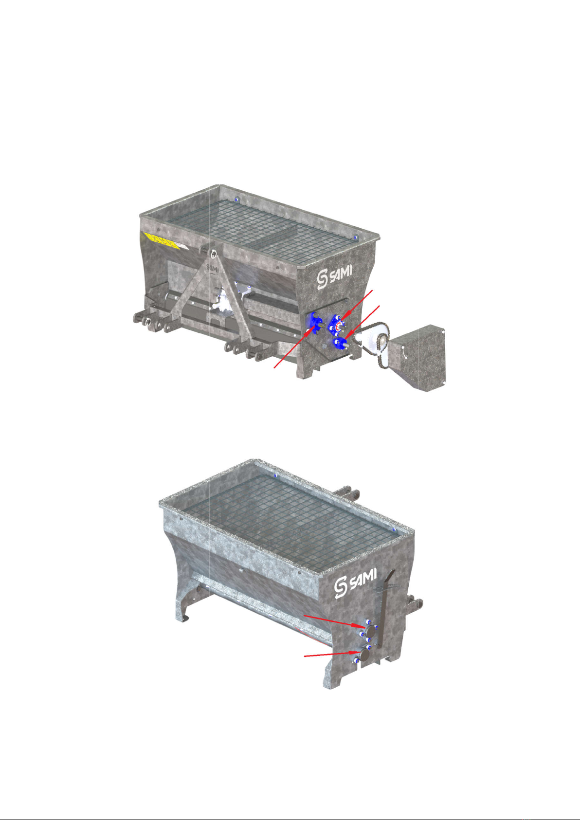
Greasing of bearings
Grease the bearings daily, depending on the intensity of use of the spreader.
and 2.
Figure 1.
Figure 2.
ION
Grease the bearings daily, depending on the intensity of use of the spreader.
Figure 1.
Greasing nipples location
Figure 2.
Greasing nipples location
Grease the bearings daily, depending on the intensity of use of the spreader.
See figure 1
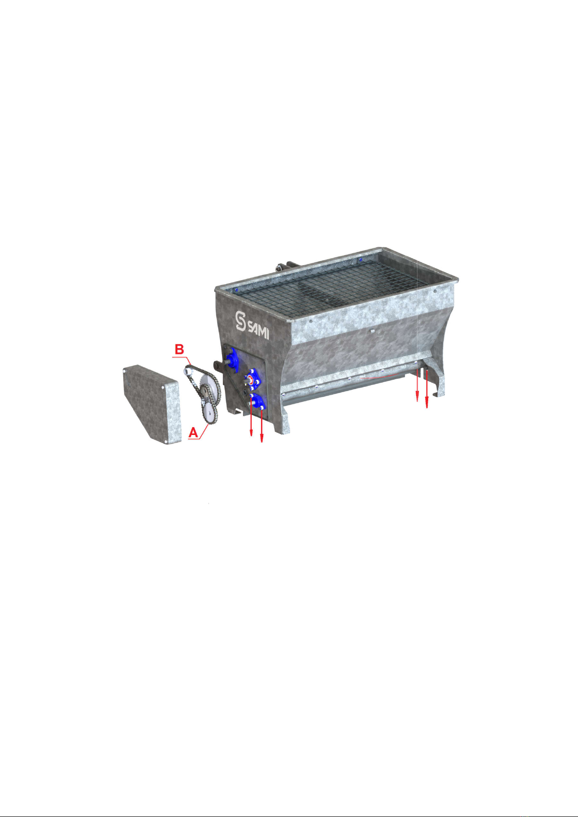
Maintenance of chain and sprockets
The chain and sprockets in the chain compartment should be greased at least once per
month of operation using an oil can. The cover of the chain compartment should always be
in place.
Tensioning of chain
Check the tens
ion of the chain at least once per month of operation
(figures 3 and 4).
Figure 3.
Tensioning of chain (A) by moving the spreading shaft.
For tensioning chain A please loose the spreading shafts bearing bolts and move the shaft
do
wn. After that, please fasten the bolts again.
Maintenance of chain and sprockets
The chain and sprockets in the chain compartment should be greased at least once per
month of operation using an oil can. The cover of the chain compartment should always be
ion of the chain at least once per month of operation
by doing the following
Tensioning of chain (A) by moving the spreading shaft.
For tensioning chain A please loose the spreading shafts bearing bolts and move the shaft
wn. After that, please fasten the bolts again.
The chain and sprockets in the chain compartment should be greased at least once per
month of operation using an oil can. The cover of the chain compartment should always be
by doing the following
Tensioning of chain (A) by moving the spreading shaft.
For tensioning chain A please loose the spreading shafts bearing bolts and move the shaft
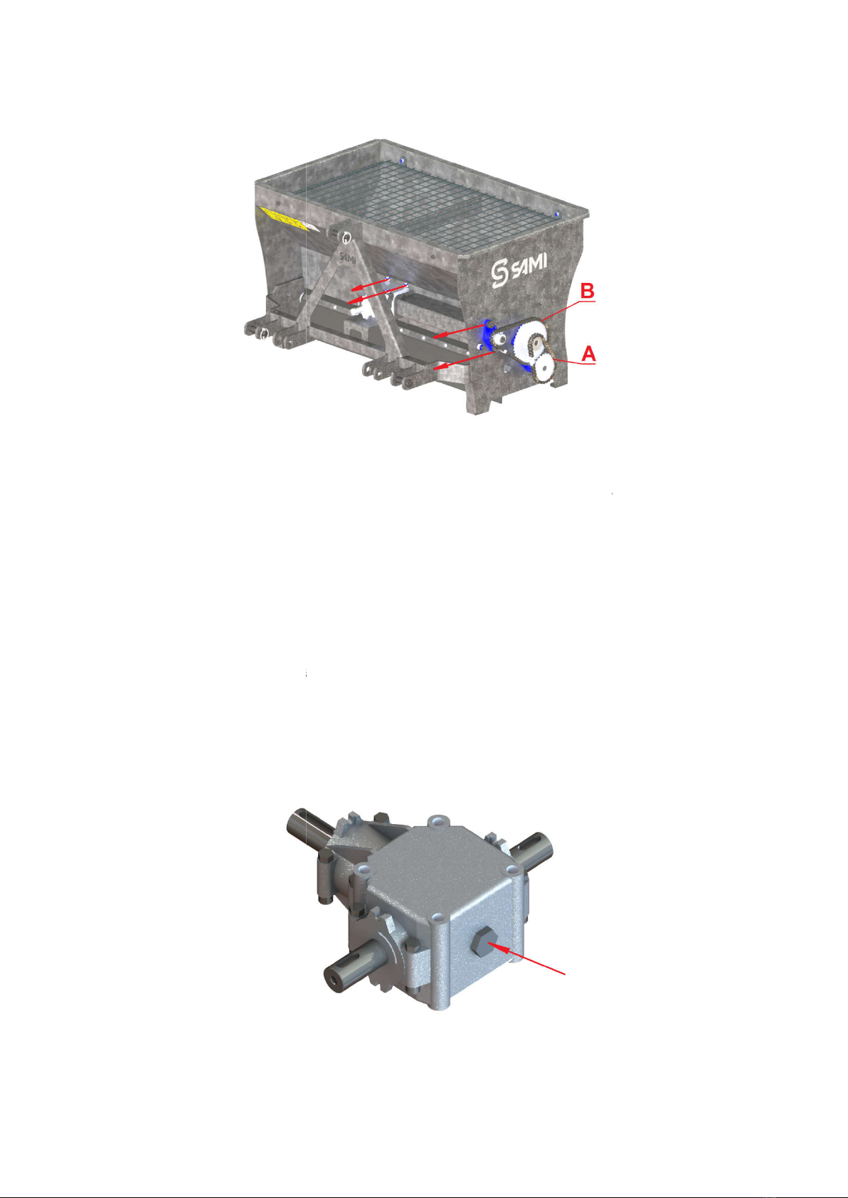
Figure 4.
Chain (B) tensioning by moving gear and chain wheel.
Loose the Gera’s and bearing’s bolts. Move both in a way shown in figure 4. Fasten bolts
again. Please be sure that the gear’s shaft is straight positioned.
GEAR BOX MAINTENANCE
Gear box is filled with oil in producer factory.
Then taking the salt spreader in use, please
working hours.
After that
please change oil after every 500 working hours.
Tank volume is 0,35 l
SAE.90EP (GL-5 80W-
90) is suitable
See figure 5.
Chain (B) tensioning by moving gear and chain wheel.
Loose the Gera’s and bearing’s bolts. Move both in a way shown in figure 4. Fasten bolts
again. Please be sure that the gear’s shaft is straight positioned.
Gear box is filled with oil in producer factory.
Then taking the salt spreader in use, please
c
hange the oil in gear box a
please change oil after every 500 working hours.
90) is suitable
Figure 5. Gear box oil cap.
Chain (B) tensioning by moving gear and chain wheel.
Loose the Gera’s and bearing’s bolts. Move both in a way shown in figure 4. Fasten bolts
hange the oil in gear box a
fter first 50

TROUBLESHOOTING
Problem Possible cause Solution
No salt is dispensed Spreading shaft has warn off Replace the spreading shaft
No salt is dispensed The salt is frozen or very wet Check the salt quality
Too much salt is dispensed The rubber has worn out
Replace the rubber
The spreader’s shafts don’t
rotate, but the PTO shaft
rotates
Check the chain. It might be
broken
Replace the chain
WARRANTY TERMS
Warranty for SAMI products is valid 12 months from the date of purchase.
- Material and manufacturing defects that occur during the warranty period are covered
by the warranty.
- When a defect occurs, please contact authorized distributor whom you bought the
product
- Please send to distributor serial number and/or year of manufacture of the product (see
the manufacturer’s data plate) together with photos, videos and detailed description of
the defect. Evidence material must contain Photographs of label, of problematic place
and of product in full.
- Distributor communicates the producer and informs the client about made decision.
- In need distributor may ask from the client to send additional information or defected
part.
- All warranty cases accepted by SAMI AS will be compensated by producer.
- The manufacturer either repairs or replaces or compensates the defective parts.
- Sub-contracted part’s warranty is provided by their manufacturer.
The warranty excludes:
- Consumables (e.g. blades, etc)
- Downtime or any other consequential loss or damage
- Transport costs (travel and freight costs)
- Overtime pay or mission allowances
- Any damage caused by operation in a negligent manner or exceeding the approved
specifications detailed in this manual is excluded.
The warranty excludes damage resulting from:

AS SAMI
Tule 20, 76505 Saue
Harjumaa, Estonia
Phone: +372 670 9040
E-mail: [email protected]
www.sami.ee
- Negligent or improper use of the product.
- Failure to observe the operating and maintenance requirements set by the
manufacturer.
- Normal wear and tear.
- Abnormal operating conditions.
- Overloading or use for other non-intended purposes.
- Lack of maintenance and checks.
- Repair works which are below standard.
- Failure due to use of incorrect oil or lubricants, contamination of the oil, or which has
served its normal life.
- Hoses which have suffered external damage.
- Using other than SAMI original spare parts and equipment.
- Long storage time (e.g. paint defects or corrosion).
- The manufacturer does not accept any responsibility for interruption of work or any
other consequential loss resulting from any failure of the product.
All warranty terms apply only to a new product purchased from a distributor authorized by
AS SAMI. The warranty does not apply to a resold product.
* This manual is a translation of original.
This manual suits for next models
1
Table of contents
Popular Spreader manuals by other brands


Fisher
Fisher POLY-CASTER 78601 owner's manual

TurfEx
TurfEx RS7200 Owner's/operator's manual

Fayat Group
Fayat Group DYNAPAC S100 operation & maintenance

Art's-Way Manufacturing
Art's-Way Manufacturing X700 Operator's manual & parts list

Ferris
Ferris Pathfinder Series Operator's manual

EASTMAN
EASTMAN CR 500 instruction manual


