Brinly BS-42BH User manual

1019911-A
1
BS-42BH-ABS-381-A
BS-381 BS-42BH
This implement is for use with garden tractors
equipped with sleeve hitch. Also, tire chains and
wheel weights are recommended.
Call Customer Service, Toll-Free: 877-728-8224
Important: This manual contains information for the safety
of persons and property. Read it carefully before
assembly and operation of the equipment!
Visit us on the web!
www.brinly.com
38" BOX SCRAPER
MODEL:
BS-381
BS-381-A
BS-42BH
BS-42BH-A
OWNER'S MANUAL
• Assembly
• Installation
• Operation
• Repair Parts
42" BOX SCRAPER

1019911-A
2
================================================================================================
English Manual
INTRODUCTION AND SAFETY
CONGRATULATIONS on the purchase of your new Brinly-Hardy Box Scraper! Your product has been designed, engineered and
manufactured to give you the best possible dependability and performance.
Should you experience any problem you cannot easily remedy, please do not hesitate to contact our knowledgeable customer
service department toll-free at 1-877-728-8224. We have competent, well trained technicians to help you with the assembly and
use of your Box Scraper.
TABLE OF CONTENTS
================================
Safety .................... 2
Parts ................... 3 - 5
Assembly ............... 6 - 10
Operation ................. 11
Maintenance ............... 11
Warranty ................. 12
REQUIRED
TOOLS
FOR ASSEMBLY
=============================
• 9/16” Wrench (1)
• 3/4” Wrench (2)
• Pliers (1)
Slip joint recommended
• Level
• Hammer
• Gloves
• Know controls and how to stop quickly,
READ THE OWNER'S MANUAL.
• Do not allow children to operate the vehicle, do not allow adults to operate
without proper instruction or without having read the owner's manual.
• Do not carry passengers. Keep children and pets a safe distance away.
• Always wear substantial footwear. Do not wear loose tting clothing that can
get caught in moving parts.
• Keep your eyes and mind on your tractor/attachment and area being
covered. Do not let other interests distract you.
• Stay alert for holes in the terrain and other hidden hazards.
• Do not drive close to creeks, ditches and public highways.
• Watch out for trafc when crossing or near roadways.
• When using any attachment, don't allow anyone near the vehicle while in
operation.
• Keep the vehicle and attachment in good operating condition and keep
safety devices in place.
• Keep all nuts, bolts and screws tight to be sure the equipment is in safe
working condition.
• The vehicle and attachment should be stopped and inspected for damage
after striking a foreign object.
• The damage should be repaired before restarting & operating the equipment.
• See tractor equipment owner's manual for safe operation of the equipment.
======================================================
RULES FOR SAFE OPERATION
LOOK FOR THIS SYMBOL TO POINT OUT IMPORTANT
SAFETY PRECAUTIONS. IT MEANS - ATTENTION: BECOME
ALERT! YOUR SAFETY IS INVOLVED.
CUSTOMER RESPONSIBILITIES
- Please read & retain this manual. The instructions will enable you to assemble and maintain your product properly.
- Please carefully read and observe the SAFETY SECTION of this manual.
- Follow a regular schedule in maintaining and caring for your Brinly-Hardy product.
• Always stop the tractor and raise Unit to transport position
BEFORE changing blade angle or reversing blade.
• Care should be taken not to "hang" the blade on surface projections
such as corners of concrete driveways.
• NEVER allow anyone to "ride" on the unit.
• Lock tractor lift handle DOWN when installing unit
on or removing from the sleeve hitch.

1019911-A
3
================================================================================================
English Manual
1
13
4
10
6
9
12
29
29
12
12
12
16
16
17
14
14
14
16
22
21
22
3
7
27
27
28 24
24
2
20
5
+15 18 +
18
15
+
11
19
16
17
14
16
14
17
16 17
14
+
11
19
14
16
14
16
12
12
12
11
11
PARTS
Ref # 1019988 Hardware Bag Qty
145M4440P Washer; SAE, Plain, 1-1/4 1
2B-1675P Nut; Hex Lock, 3/8"-16 1
B-4813-10 Blade, 38" 1
31019748-10 Blade, 42" 1
4B-2376-10 Angling Lever 1
5B-2578 Pin; Clevis, 7/16 x 2-3/8 1
1019747* Pin; Magnetic Hitch 1
6B-3717 Grip; Vinyl, 3/8 x 1-1/4 1
7B-2596-10 Blade Mount Plate 1
8B-5922 Logo Decal 1
9B-4265-10 Hitch Assembly 1
10 B-4351-10 Drawbar 1
11 2M1620P Bolt; Hex Head, 1/2 x 1-1/4" 4
12 10M1216P Bolt; Carriage, 3/8 x 1" 8
Ref # 1019988 Hardware Bag Qty
13 10M1240P Bolt; Carriage, 3/8 x 2-1/2" 1
14 30M1200P Nut; Reg Hex, 3/8 - 16 10
15 30M1600P Nut; Hex, 1/2"-13 4
16 40M1200P Washer; Lock, 3/8" 10
17 45M1313P Washer; SAE Flat, 3/8" 6
18 40M1600P Washer; Lock, 1/2" 4
19 45M1717P Washer; Flat, 1/2" 2
20 50M0416P Pin; Cotter, SS 1/8 x 1" 1
B-4819-10 Scarifier Bar Assembly, 38" 1
21 1019750-10 Scarifier Bar Assembly, 42" 1
22 B-4814-10 Plate; Side 2
24 1019983 Pin; Linch, 5/16" 2
27 B-5343-10 Bracket; Weight Mount 2
28 B-5344-10 Bracket; Weight Support 1
29 10M1220P Bolt; Carriage, 3/8 x 1-1/4" 2
* 1019747
Included on
some models.

1019911-A
4
================================================================================================
English Manual
DO NOT RETURN PRODUCT IF YOU ARE MISSING PARTS.
Please Call: 1 (877) 728-8224
PARTS: HARDWARE IDENTIFIER
Illustrations on this page
are to scale for faster
identication of hardware
during assembly.
Pin; Cotter,
1/8 x 1" (x1) . . . .
50M0416P
20
Washer: Flat
1/2” (x2) . . . . . . .
19
45M1717P
Washer: Lock
1/2” (x4) . . . . . . . . . .
40M1600P
18
Washer: Lock
3/8” (x10) . . . . . . . . . .
40M1200P
16
Washer: Flat
3/8” (x6) . . . . . . . . . .
17
45M1313P
Washer: Flat
1-1/4” (x1) . . . . .
45M4440P
1
Nut: Hex Lock, 3/8” (x1) . . .
B-1675P
2
Nut: Hex, 3/8” (x10) . . . . . .
30M1200P
14
Nut: Hex, 1/2” (x4) . . . . . .
30M1600P
15
Bolt: Carriage, 3/8 x 2-1/2” (x1) . . . . . . . . . . . . . . . . . . . .
10M1240P
13
Bolt: Carriage
3/8 x 1” (x8) . . . . . . . . .
10M1216P
12
Bolt: Carriage
3/8 x 1-1/4” (x2) . . . .
10M1220P
29
Bolt: Hex Head
1/2 x 1-1/4” (x4) . . .
2M1620P
11
5Pin, Clevis: 7/16" x 2 3/8" (x1) . . . . . .
B-2578
. . . .
Pin: Linch
5/16 (x2) . . .
1019983
24

1019911-A
5
================================================================================================
English Manual
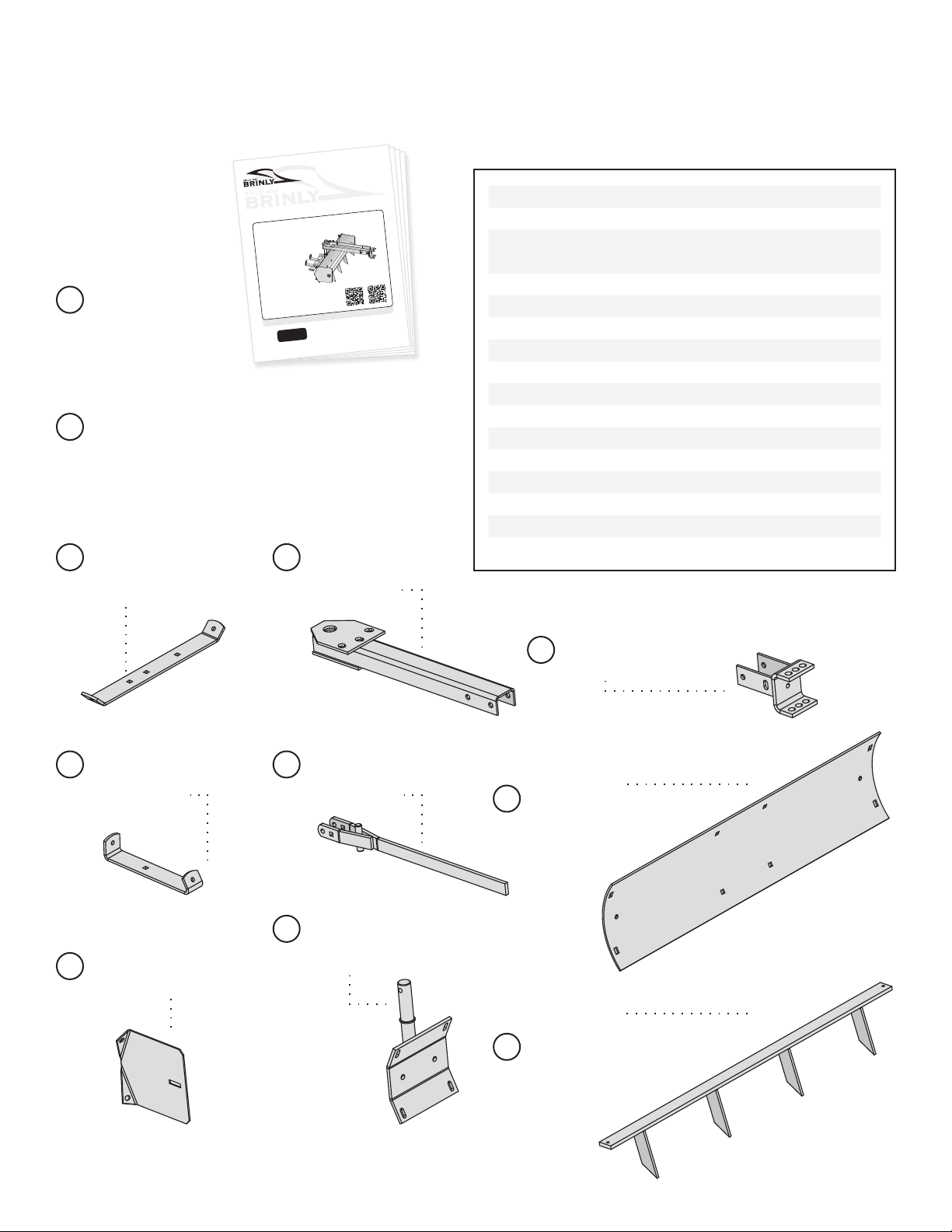
PARTS: CONTENTS OF SHIPPING CARTON
Owner's
Manual (x1) . . . .
1019911
A
Hardware Bag (x1) . . . . . . . . . . . . . . . . . . . . . . . .
1019988
B
1019911-A
1
BS-42BH-ABS-381-A
BS-381 BS-42BH
English, Spanish and
French Manual
This implement is for use with garden tractors
equipped with sleeve hitch. Also, tire chains and
wheel weights are recommended.
Call Customer Service, Toll-Free: 877-728-8224
Important: This manual contains information for the safety
of persons and property. Read it carefully before
assembly and operation of the equipment!
Visit us on the web!
www.brinly.com
38" BOX SCRAPER
MODEL:
BS-381
BS-381-A
BS-42BH
BS-42BH-A
OWNER'S MANUAL
• Assembly
• Installation
• Operation
• Repair Parts
42" BOX SCRAPER
Weight Support
Bracket (x1)
B-5344-10
28
Weight Mount
Bracket (x2)
B-5343-10
27
Drawbar
Assembly (x1)
B-4351-10
10
Angling
Lever (x1)
B-2376-10
4
Blade Mount
Plate (x1)
B-2596-10
7
Side Plate (x2)
B-4814 -10
22
Hitch Assembly (x1)
B-4265
9
3
38" Blade (x1)
B-4813-10
42" Blade (x1)
1019748-10
Ref # 1019988 Hardware Bag Qty
145M4440P Washer; SAE, Plain, 1-1/4 1
2B-1675P Nut; Hex Lock, 3/8"-16 1
5B-2578 Pin; Clevis, 7/16 x 2-3/8 1
1019747* Pin; Magnetic Hitch 1
6B-3717 Grip; Vinyl, 3/8 x 1-1/4 1
11 2M1620P Bolt; Hex Hd, 1/2 x 1-1/4 4
12 10M1216P Bolt; Carrige, 3/8 x 1" 8
13 10M1240P Bolt; Carriage, 3/8 x 2-1/2" 1
14 30M1200P Nut; Reg Hex, 3/8"-16 10
15 30M1600P Nut; Hex, 1/2"-13 4
16 40M1200P LockWasher, 3/8" 10
17 45M1313P Washer; SAE Flat, 3/8 6
18 40M1600P Washer; Lock, 1/2" 4
19 45M1717P Washer; Flat 1/2" 2
20 50M0416P Pin; Cotter, SS 1/8 x 1 1
24 1019983 Pin; Linch, 5/16" 2
29 10M1220P Bolt; Carriage, 3/8 x 1-1/4" 2
* 1019747 Included on model BS-42BH-A only.
38" Scarier Bar Assembly (x1)
B-4819-10
21 42" Scarier Bar
Assembly (x1)
1019750-10

1019911-A
6
================================================================================================
English Manual
ASSEMBLY
x2
Assembly Tips
Illustrations on page 4 are to-scale. For faster identification of the hardware
during assembly, simply lay the hardware on top of these illustrations.
It is recommended that you carefully read
this Owner's Manual before starting assembly.
Additional info and videos are
available on our website:
brinly.com
These QR codes
link directly to
the Box Scraper
product pages.
Align the Blade (3) with
the Blade Mount Plate (7),
as illustrated.
On the inner curve of the blade,
nd the two TOP CENTER HOLES
and run two 3/8" x 1" Carriage
Bolts (12) through.
On the back, add a 3/8" Flat Washers
(17), 3/8" Lock Washer (16) and secure
LOOSELY with 3/8" Hex Nuts (14).
Do not tighten fully (YET).
Step 1
tractor
right hand side
left hand side
1019911-A
4
================================================================================================
English Manual
DO NOT RETURN PRODUCT IF YOU ARE MISSING PARTS.
Please Call: 1 (877) 728-8224
PARTS: HARDWARE IDENTIFIER
Illustrations on this page
are to scale for faster
identication of hardware
during assembly.
Pin; Cotter,
1/8 x 1" (x1) . . . .
50M 0416P
20
Washer: Flat
1/2” (x 2) . . . . . . .
19
45M 1717P
Washer: Lock
1/2” (x4) . . . . . . . . . .
40M1600P
18
Washer: Lock
3/8” (x10) . . . . . . . . . .
40M1200P
16
Washer: Flat
3/8” (x6) . . . . . . . . . .
17
45M 1313P
Washer: Flat
1-1/4” (x1) . . . . .
45M4440P
1
Nut: Hex Lock, 3/8” (x1) . . .
B-1675 P
2
Nut: Hex, 3/8” (x10) . . . . . .
30M1200P
14
Nut: Hex, 1/2” (x4) . . . . . .
30M1600P
15
Bolt: Carriage, 3/8 x 2-1/2” (x1) . . . . . . . . . . . . . . . . . . . .
10M1240P
13
Bolt: Carriage
3/8 x 1” (x8) . . . . . . . . .
10M12 16P
12
Bolt: Carriage
3/8 x 1-1/4” (x2) . . . .
10M1220P
29
Bolt: Hex Head
1/2 x 1-1/4” (x4) . . .
2M162 0P
11
5Shear Pin: 7/16" x 2 3/8" (x1) . . . . . .
B-2578
. . . .
Pin: Linch
5/16 (x2) . . .
101998 3
24
Right hand (R.H.) and Left
hand (L.H.) are determined from
the operator's position while
seated on the tractor.
16 17
14
16
17
14
12
12
7
3
14 1716 12
BLADE
BLADE MOUNT
PLATE +
73
BS-42BH
BS-42BH-A
BS-381
BS-381-A

1019911-A
7
================================================================================================
English Manual
ASSEMBLY
x2
Align the Weight
Mount Brackets (27).
(V-Angle End next to
Blade Mount Plate) to two
Bottom Holes Blade and
Blade Mount Plate.
On the inner curve
of the blade, nd the two LOWER
CENTER HOLES and run two 3/8" x
1-1/4" Carriage Bolts (29) through.
On the back, add a 3/8" Lock Washer
(16) and secure LOOSELY with 3/8"
Hex Nuts (14).
Do not tighten
fully (YET).
x2
Step 3
Step 2
14 16 29
WEIGHT
MOUNT
BRACKETS
BLADE
& MOUNT
PLATE
+
27 3
+
7
29
16
14
29
16
14
27
27
Attach the Weight
Support Bracket (28).
Align the support bracket
(28) to bottom of weight
mount brackets (27), as
illustrated.
From above, run two 3/8" x 1"
carriage bolts (12) through both
brackets.
Secure from below with a 3/8"
lock washer (16) and 3/8" hex
nut (14) on each bolt.
NOW SECURELY TIGHTEN
ALL HARDWARE FROM STEPS 1-3.
12
14
16
16
14
16
14
28
27
27
12
12

1019911-A
8
================================================================================================
English Manual
ASSEMBLY
x2x2
Step 4
19 11
15 18
- Add the drawbar (10) to the blade mount
plate post (7) as illustrated. Follow with the large
at washer (1).
- Slide the handle grip (6) on the end of the
angling lever (4), then align it on the mount
plate post (7) as illustrated.
- Insert the 7/16" x 2-3/8" Shear pin (5) through
the round holes at the end of the lever and post.
Secure with the 1/8" x 1" cotter pin (20).
Align the Hitch Assembly (9) with the Drawbar (10) as illustrated
here. Add a at washer (19) to two 1/2" x 1-1/4" Hex Bolts (11) as
shown. Run the bolts through the rst holes of the hitch assembly
and drawbar.
Add a Lock Washer (18) and nut (15) to each bolt.
Do not tighten fully (YET).
Run two 1/2" x
1-1/4" Hex Bolts (11) through the hitch
assembly and drawbar, as illustrated.
Add a Lock Washer (18) and nut (15) to
each bolt. Do not tighten fully (YET).
Step 5-A
5
1
20
10
4
6
7
9
10
19
11
11
15
15
18
18
19
9
11
15
15
18
18
11
NOTE: Bend the
cotter pin (20) ends as
illustrated to secure.
11
15 18
Note: Slightly
longer edge
points up.
NOTE: Flip drawbar
over for next step.

1019911-A
9
================================================================================================
English Manual
x4
Align a Side Plate (22)
with the Blade (3).
From the inner corner, attach
the side plate (22) running two
3/8" x 1" Carriage Bolts (12)
through both parts.
Secure each bolt using a Flat
Washer (17), Lock Washer (16)
and Hex Nut (14).
Do not fully tighten (yet).
ASSEMBLY
- Insert the 3/8" x 2-1/2" Carriage Bolt (13)
through the remaining two holes (square)
in the angling lever (4).
- Secure with a 3/8" Hex Lock Nut (2).
2
4
13
Step 5-B
Step 6
NOTE: Tighten the lock nut (2) just
enough to remove any "looseness" in the
angling lever (4) - it must be free to move up
and down without binding.
22
3
12
17
17
14
14
16
16
12
Repeat this step, attaching the
second side plate on the other side
of the Blade.
12
BLADE
SIDE
PLATE +
22 3
14 1716

1019911-A
10
================================================================================================
English Manual
Align the Scarier Bar
Assembly (21), teeth points
down and facing forward.
Slide the bar ends through the
slots of Side Plates (22) as shown.
Secure in place by installing
Linch Pins (24) through the holes on the
end of the Scarier Bar (21) as illustrated
here.
Assembled Scarier Bar:
Step 7
ASSEMBLY
21
22
22
24
24
Step 8
Box Scraper is ready to use!
Attach the completed Box Scraper to the Sleeve Hitch of your tractor, in the middle
hole of the Box Scraper Hitch. Hitch pin (5) furnished with your hitch.
Now the Stabilizer Bolts on the Hitch need to be tightened
against the Yoke on Box Scraper to prevent any "side sway."
• Position the Tractor (with Box Scraper) on a hard, level surface.
• Lower the box scraper and check to make sure it is level side-to-side,
loosen the four 3/8" carriage bolts holding the box scraper to the post
to adjust as necessary, and retighten hardware. Refer to steps 1 & 2.
• Place a level on top of Drawbar-move Hitch Assembly until Drawbar
is level, front to back. Refer to Step 4.
• The operating depth of the Box Scraper needs to be set now. Make
sure the tractor hitch is free to allow box scraper to go below ground
level, but still maintaining a 5" transport height with the Hitch raised.
• Refer to your tractor and/or sleeve hitch manual for any necessary
adjustments.
Adjustable
Turnbuckle
Angling
Lever
Drawbar
Point of Blade Edge
MUST BE FREE TO GO
BELOW GROUND LEVEL
( See Sleeve Hitch Manual )
Now securely tighten all
hardware from steps 4 and 6.

1019911-A
11
================================================================================================
English Manual
OPERATION
• After the Box Scraper is properly adjusted and mounted to the
Tractor, many different operations can be accomplished, some
of which are: leveling dirt and gravel, spreading a pile of loose
material, filling small holes, cleaning up debris, snow removal,
scarifying, etc. NOTE: The Box Scraper is not recommended for
use in reverse gear.
• The Tractor speed while operating the unit, should be governed by
the task to be accomplished.
• While leveling or grading, do not attempt to cut excessive amounts
of hard-packed material at a high rate of speed.
• Use of the Scarifier is recommended when leveling and grading
hard-packed material, to aid in breaking up the surface or gravel
layer. NOTE: Operate at a speed which allows loose material that
has piled up on the face of the Unit to be deposited in low areas.
• Weight (concrete / patio blocks, etc.) can be added to tray and
secured using tie downs through holes in tray flanges.
OPERATION AS A
BOX SCRAPER AND SCARIFIER
• Your unit may be used as a Rear Blade by removing the
Scarifier and Side Plates. (Disassemble by reversing assembly
steps 7, then step 6).
• Various angles (left and right) are obtained by lifting Angling Lever,
rotating the Blade to the desired angle, then lowering the Angling
Lever into the locking hole.
• To use the Blade with the Tractor in the reverse gear, raise the
Angling Lever, rotate the Blade 180 degrees and lock into the
desired position by flipping the angling lever.
• The Blade is designed to be used in a variety of light jobs: such as
leveling, scraping, raking, back-filling, snow removal, etc.
• Weight (concrete / patio blocks, etc.) can be added to tray and
secured using tie downs through holes in tray flanges.
OPERATION
AS A REAR BLADE
MAINTENANCE
• After the Blade Edge has worn
considerably, it should be rotated (from
bottom to top) to provide a new edge.
Remove the four 3/8" Carriage Bolts, rotate the Blade and then
re-assemble the Blade with the new edge on the surface.
• Lubricate all pivoting points and the Hitch Pin with a drop or
two of 30 weight oil before each operation.
• Frequently (at least every 8 hours of use) see that all bolts
and nuts are tight.
• When the Unit is not being used, remove all dirt, scale and
rust; then touch-up with paint.
• Apply a coat of grease, oil or rust preventative to blade
edge, scarifier and other areas that appear to have
"scoured" from operation.
• Always store in a dry place.
QUALITY CONTINUES
WITH QUALITY SERVICE
If you have installation questions, are missing parts or need
replacement parts, don’t go back to the store!
Please find your product serial number and model number, then
contact our Customer Service department:
SERVICE
In North America and Canada call
Toll-Free: 877-728-8224
Chat online: www.brinly.com
Email: customerservice@brinly.com

1019911-A
12
Brinly-Hardy Company warrants only to the original retail
purchaser that this product will remain free of defects in
workmanship and materials under normal use and service for a
period of one (1) year (NOTE: ninety (90) days for commercial
or rental use) commencing with the date of purchase.
Any parts found to be defective within the warranty period will
be replaced, with proof of date of purchase, at Brinly Hardy
Company's expense. Our obligation under warranty is expressly
limited to replacement or repair, at our option of parts which
are defective in material or workmanship within thirty (30) days
of receipt of the parts. This warranty does not apply to damage
caused by unreasonable use, including failure to provide
necessary maintenance, nor does it apply to any transportation
or labor charges.
WE MAKE NO OTHER EXPRESS WARRANTY NOR IS
ANYONE AUTHORIZED TO MAKE ANY ON OUR BEHALF.
ANY IMPLIED OR STATUTORY WARRANTIES, INCLUDING
ANY WARRANTY OF MERCHANTABILITY OR FITNESS FOR A
PARTICULAR PURPOSE, ARE LIMITED TO THE DURATION OF
THIS WRITTEN WARRANTY. WE SHALL NOT BE LIABLE FOR
CONSEQUENTIAL OR INCIDENTAL DAMAGES OF ANY KIND.
MADE IN U.S.A.
LIMITED WARRANTY
English Manual
Brinly-Hardy Company • 3230 Industrial Parkway • Jeffersonville, IN 47130 • (877) 728-8224 • brinly.com
Additional info and
videos are available on
our website: brinly.com
These QR codes
link directly to the Box
Scraper product page.
BS-42BH-ABS-381-A
BS-381 BS-42BH
This manual suits for next models
3
Table of contents
Other Brinly Tractor Accessories manuals