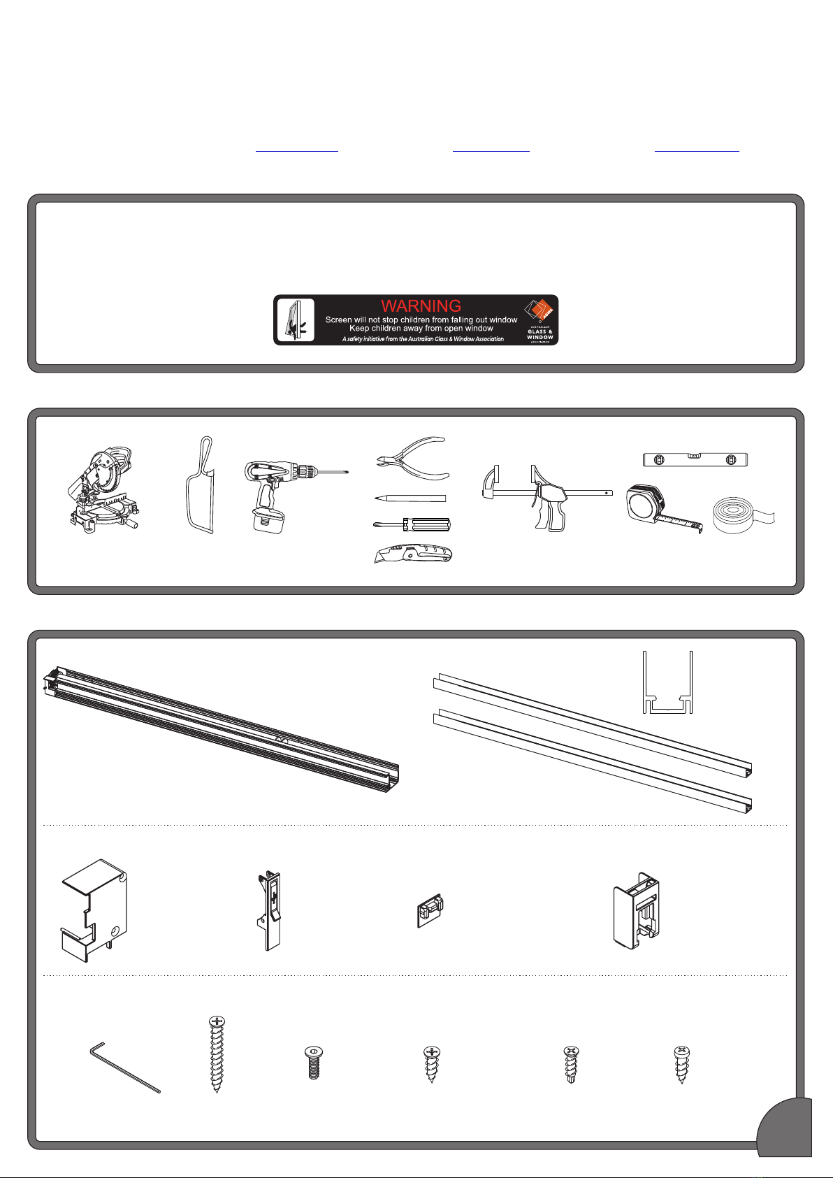
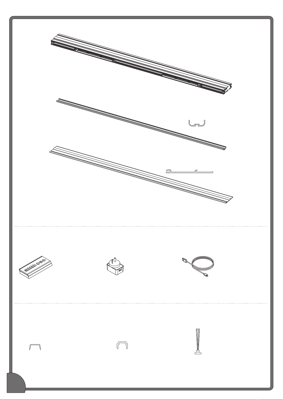
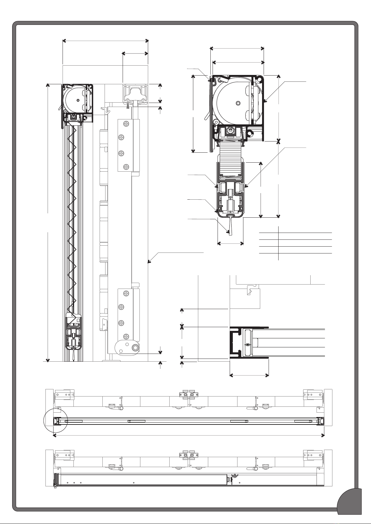
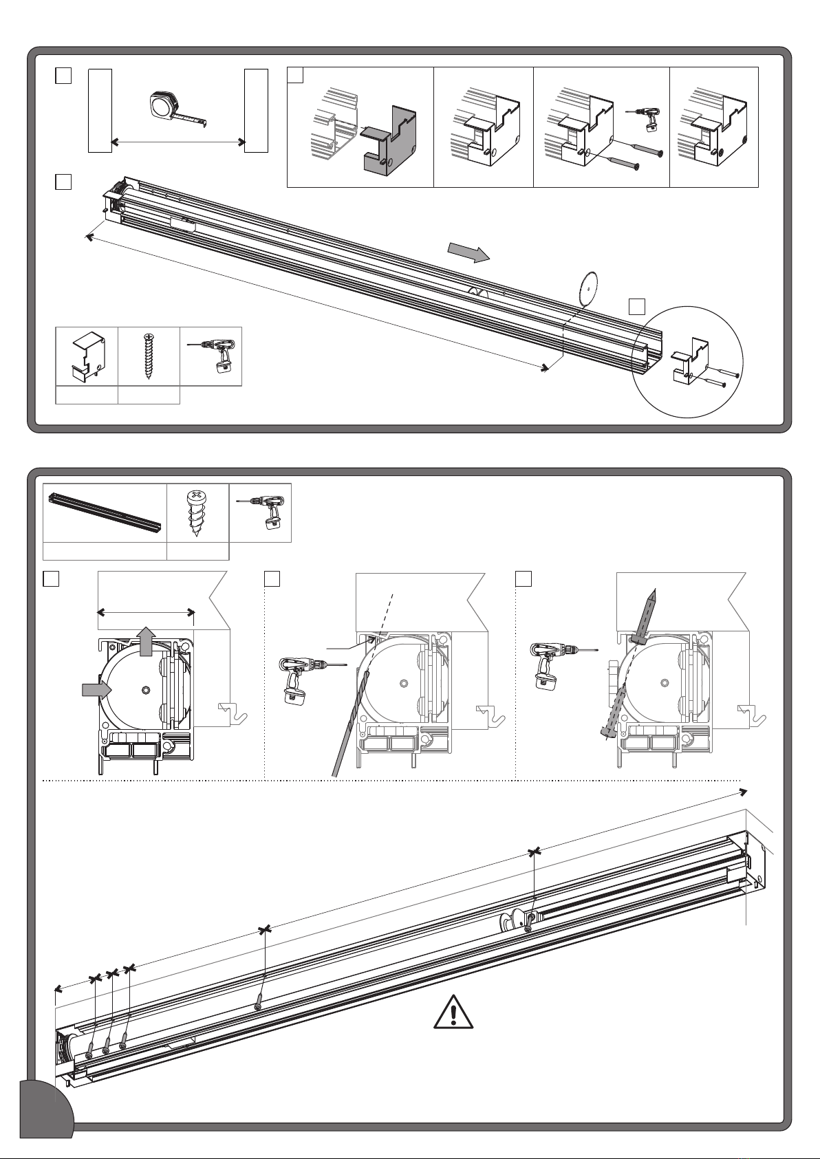
BRIO 312 User manual

1
Brio Australia
P: +61 2 87186718
W: brio.com.au
Brio UK
P: +44 191 2291224
W: briouk.com
Brio USA
P: +1 585 3195599
W: briousa.com
Brio®312 Retractable Pleated Insect Screen
INST312S REV 4 - JULY 2020
x2
Note: Blade suitable
for aluminium
Note:
Low adhesive
Note: Blade suitable
for aluminium
Recommended Tools
x2
RST
CHANNEL
MOTOR
HOUSING
ASSEMBLY
x1
Box 1 - Framing Kit
312 Screen Fitting Pack
x1
HRS-002
END CAP
(RIGHT)
x2
HRS-015
MESH SUPPORT (H)
HRS-UCA
USB COVER
HRS-016
NOSE END CAP
x1 x2
WS-AK
ALLEN KEY
x1
312 Screen Fixing Pack
x2
TEKS-62020CX
x28
SPK-SG8GX19SS
x2
SC8GX37.5S SP8X25S
x11x1
SCM3X10DS
Read Installation Instructions carefully before
proceeding. Ensure that Installation Instructions
and Hex Drive remain with the homeowner.

2
Box 2 - Screen Kit
x1
SCREEN
ASSEMBLY
x1
HRS-F
FASCIA
x1
HRS-NCEX
NOSE COVER
Remote, Motor Charger and Cable
x1 x1
ACM-MT03-MCWT
CHARGER
ACM-MT03-C4WT
CHARGER CABLE 4M
x1
x1,2 or 3
WS-COVEXP
DUST COVER
Covers and Seal
x1
ACM-MT02-R5BK
REMOTE
P48X16
SEAL
x2
WS-HDPEX
HANDLE BAR TRIM
Box 2 - Screen Kit

3
138
41
51
48.5
31
7
12
62.4
72.9
52
A
24
40
30
2.5
17.5
HEIGHT
1200
1400
1600
1800
DIMENSION A (OVERALL)
75
80
86
92
OPENING WIDTH (OW)
OPENING
HEIGHT
(OH)
A.
VIEW A.
WEATHERFOLD
4s SERVERY NON
MORTICE HARDWARE
MOTOR
HOUSING
ASSEMBLY
SCREEN
ASSEMBLY
PS48X16
SEAL
HRS-NCEX
COVER
HRS-F
FASCIA
WS-HDPEX
HANDLEBAR
TRIM
SCREEN ASSEMBLY
MOTOR HOUSING ASSEMBLY
System Overview

Fitting motor housing
Cut & assembly of motor housing
4
MW (MOTOR HOUSING WIDTH) = OW - 28.5
CUT THIS END ONLY
1 2 3 4
OW (OPENING WIDTH)
JAMB
JAMB
A
B
C
C
HEADBOARD HEADBOARD HEADBOARD
AB C
SC8GX37.5S
HRS-002
53.5 25 25 200 400
ADDITIONAL 4 x 400
ON A 2600 SCREEN
ENSURE DRILLED
HOLE IS
PERPENDICULAR
TO FACE
Assistance may be required to
install motor housing assembly
49
SP8X25S
HRS-002 SC8X37.5S
MOTOR HOUSING SP8X25S

5
H
HEADBOARD
CL
JAMB
HEADBOARD
65
Repeat steps for other Jamb Channel (RST)
Preparing and fitting jamb channel (RST)
INSERT
LEVEL
A B
CD
B
C
A
D
D
D
D
A
CL (CHANNEL LENGTH) RST = H - 65
SG8GX19SS
Cutting screen assembly
==
(B)
MAX 100
SS (SCREEN SIZE)
refer to actual screen sizes in table below
SW (SCREEN WIDTH)= OW - 45
(B)
MAX 100
Plastic
Wrapping
Plastic
Wrapping
OW (OPENING WIDTH)
JAMB
JAMB
A
DO NOT REMOVE WRAPPING BEFORE CUTTING
Ensure the screen assembly is tightly bound as supplied
SS (SCREEN SIZE) - SW (SCREEN WIDTH)
2
CUTTING SIZE (B) =
RST SC8GX19SS
SCREEN ASSEMBLY
Product Code Screen Size (mm)
RSWA-XX-20BK 1955
RSWA-XX-22BK 2155
RSWA-XX-24BK 2355
RSWA-XX-26BK 2555

6
Mesh Retainer & End Caps
REMOVE
Carefully remove
plastic wrap and tape
to free the cassettes
INSERT INSERT
SCREEN ASSEMBLY
AB
C
D
G
J
K
HRS-015
REMOVE
HRS-016
H
I
L
M
Cords must cross
over in the nose
HRS-016
F
E
HRS-015
HRS-015 HRS-016 WS-AK
Slide end caps
(HRS-016) over
the cassette
CASSETTE CASSETTE
SCREEN ASSEMBLY
Insert bearing
with pivot action
Insert bearing
with pivot action
Slide end caps
(HRS-016) over
the cassette
Insert end cap
into the screen
extrusion
Insert end cap
into the screen
extrusion

7
CUT WS-HDPEX TO FIT OPENING AS SHOWN
45°
ASSEMBLED SCREEN WIDTH (ASW)
45°
Cut end at 45° to create a lead in edge to help snap in the trim
B C
D
Cut handle bar trim to size
Clip in handle bar trim
A
Ensure mesh is compressed
Low adhesive tape
FClip in handle bar trimFlip screen to clip handle bar
trim on the other side
Nose Trim
WS-HDPEX
E
G H
APPLY

8
A B
SCREEN ASSEMBLY
REMOVE
APPLY
Low adhesive tape
D
E
F
CLIPS INTO
MOTOR
HOUSING
EXTRUSION
F
PUSHES
AGAINST
INSIDE OF
CHANNEL
E
Screen Assembly
C

9
DO NOT OVER
COMPRESS SCREEN
DO NOT OVER
COMPRESS SCREEN
I
H
I
J
H
K
J
K
x2
REMOVE
REMOVE

10
b
a
b
A
C
B
CA
Align cords on end rollers
B
Align cords on end rollers
Align cords on
individual rollers
Ensure cords are not twisted, tangled or caught on the clamps
a
b
a
b
a
Fitting cassettes & handlebar adjustment
Ensure anchors have been
released as per page 6
TEK-62020CX WS-AK

CHANNEL (RST)
INSERT
CASSETTE
SILL
ROTATE
PIVOT
SLIDE
CORDS
SILL
SILL
SILL
Ensure cords are
on top of the cassette
D E F G
b
aa
ba
b
TEK-62020CX
a
b
SILL
ADJUSTABLE
ANCHORS
11
ADJUST TO TAKE UP SLACK
H I
1
2

12
RELEASE
TENSION
INCREASE
TENSION
ADJUST
INCREASE
TENSION
RELEASE
TENSION
3
1
2
P
OQ R
J
L
M
Lift and support handle bar
to access adjustment anchors
N
REMOVE
K
Gently guide the
handle bar down
1
2
Lift handle bar to the clip

Preparing and fitting nose cover
HRS-NCEX PS48X16
OW (OPENING WIDTH)
JAMB
JAMB
A
W - 67[2 ⅝]
B C
D E
Cut Seal (P48X16)
(Same length as HRS-NCEX)
CUT
INSERT
REMOVE
REMOVE
FFit Nose Cover (HRS-NCEX).
FITS BETWEEN
HRS-NCEX
SCREEN ASSEMBLY
Screen is now ready to setup the motor
Align cords on end rollers Align cords on end rollers
Align cords on
individual rollers
13
DOUBLE CHECK:
HRS-016

ACM-MT03-MCWT ACM-MT03-C4WT
P1 BUTTON
USB PORT
Flashing “green”
=
Charging
Solid “green”
=
Charged
Flashing “red”
=
Recharge +
10 x beeping
Fully charge the battery before use.
Motor is to be charged for 6 hours
ACM-MT02-R5BK
UP BUTTON
STOP BUTTON
DOWN BUTTON
CHANNEL
LOCK
Motor & Remote
1
2
3
A
B
14

Remote setup
15
Upper Limit Template
TOP
BOTTOM
1800
Pair motor with controller - Important: Step B and C are done together
ASelect channel on controller BHold P1 button on motor head
P1 button
Motor Response
RELEASE P1
Approx.
JOG
x1 2SECS
x1
EXT. BEEP
Motor Response
JOG
x2
x3
BEEP
CHold STOP on controller
CHANNEL
Note the corresponding LED next
to each channel
LED
Complete step
within 3 secs
of pressing the
P1 button on
motor head
ACM-MT02-R5BK
Cut out template
WS-AK
Use Allen Key
to press button
1600
1400
1200
Low
Adhesive
Tape
APPLY
APPLY
ALIGN
TO END
CAP
Setting Lower limit
AMove screen to the desired highest
position by pressing the UP button
Motor Response
JOG
x2
x3
BEEP
BTo save lower limit, hold
DOWN and STOP
Do not over
extend the
travel, as the
cord may spool
out of the bobbin Approx. 5SECS
SEAL
TOUCHING
THE BASE
LOWER LIMIT
BASE
STOP BUTTON

16
Setting cord and upper limit
AUpon setting the lower limit the
cord on the bobbin may not be
set correctly. Using the Allen Key
push cord towards the right
Use Allen Key
to push cords
BPerform 3 quick presses on the
remote to do approx 1/2 a turn. Push
cords again to the right
Use Allen Key
to push cords
x3
ALIGN
TO TOP
OF
HANDLE
BAR
Move screen to the desired highest
position by pressing the UP button
Motor Response
JOG
x2
x3
BEEP
DTo save upper limit, hold UP and STOP
Approx. 5SECS
UPPER LIMIT
Quick Press = Step
Long Press = Continuous Travel
When close to the line on the template,
use quick press to align. The motor to
screen connection may be damaged
if the template is not used
C E Operate the screen down and up twice.
To enure the cord is spooling correctly.
Inspect that the cord
is winding correctly
USB PORT P1 BUTTON AND
BATTERY LIGHT INDICATOR
ACCESS PORT
A B C
2
Fit USB Cover
HRS-UCA SCM3X10DS WS-AK
Close cover when not in use
1
TOP
BOTTOM
1800
1600
1400
1200

17
HRS-F
OW (OPENING WIDTH)
JAMB
JAMB
A
OW - 18[¾]
B
Take care not
to scratch the
surface
C1
2
Initial Operation
Operate UP and DOWN 5 times to settle the spooling of cord
Fascia

Channel Covers
H - 90[3.54]
45°
45°
Cut at 45° to create a lead in edge
to help snap in the cover
If multiple WS-COVEXP
are required, place shortest
length closest to the sill
Cords must pass
above Channel Cover
Repeat steps for other
T)Jamb Channel (RS
WS-COVEXP
H (OPENING HEIGHT)
JAMB
JAMB
AHEADBOARD B C
D
1
2
3
1
Installation complete
18

19
Additional Information
Battery Check Function
AScreen must be at Upper Limit BScreen moves to percentage of
battery change remaining
Motor Response
Approx. 5SECS
Hold UP
Upper Limit
Lower Limit
Percentage of battery
charge remaining
Remote battery replacement
CR2430 BATTERY
POSITIVE [+]
84[ ]3⁄
Ø [ ]x19[ ]4.5 ⁄ ⁄
Wall mounting the remote
BA C D E
B
A
C D E F

20
P1 Button Motor state test
This table describes the function of a short P1 Button press/ release
(<2 seconds) depending on current motor configuration
P1
Press
Condition Function
Achieved
Visual
Feedback
Audible
Feedback
Function
Described
Short
Press
If limit is NOT set None No Action None No Action
If limits are set Operational
control of motor
run to limit. Stop
if running
Motor Runs None Operational control
of motor after pairing
and limit setting is
completed first time
If motor is in
“Sleep Mode”
& limits are set
Wake and
control
Motor wakes
and runs in a
direction
None Motor is restored from
Sleep Mode and RF
control is active
P1 Button Functions
Troubleshooting
Problem Cause Remedy
Battery in motor is depleted Recharge with compatible charger (see page 14)
Transmitter battery is discharged
Motor is not responding
Replace battery (see page 19)
Battery is inserted incorrectly
into transmitter
Check battery polarity
Radio interference/ shielding Ensure transmitter is positioned away from metal objects and the
aerial on motor or receiver is kept straight and away from metal
Receiver distance is too far
from transmitter
Move transmitter to a closer position
Charging failure Check power supply to motor is connected and active
Battery voltage is low Recharge with compatible charger
Motor beeps x10 when in use
Multiple motors are paired to
the same channel
Always reserve an individual channel for programming functions.
Use Sleep Mode to program individual motors.
Cannot program a single
motor (multiple motors respond)
P1 BUTTON ON
MOTOR HEAD
2. Motor Response
1. Use Allen Key to press and hold P1 Button for 14 seconds.
RELEASE P1
JOG
x4
x4
EXT. BEEP
Use Allen Key
to press and hold button for 14 sec.
Resetting Upper and Lower Limits
P1 BUTTON ON
MOTOR HEAD
3. Repeat steps to pair motor with controller and set limits
- refer pages 15 & 16.
Table of contents
Other BRIO Insect Control Equipment manuals