manuals.online logo
Brands
  1. Home
  2. •
  3. Brands
  4. •
  5. British General
  6. •
  7. Accessories
  8. •
  9. British General FBS28G Instruction manual

British General FBS28G Instruction manual

Technical Data
Round Pin And Export Socket Outlets
Brief product description: Features:
Product Images
Black Nickel
Brushed Steel
Polished Brass
Polished Chrome
FBN28B
FBS28G
FPB28B
FPC28G
FPC28W
FBN29B
FBS29G
FPB29B
FPC29G
FPC29W
FBN27B
FBS27G
FPB27B
FPC27G
FPC27W
The screwless slim line design in a range of finishes
will blend with any décor - suitable for domestic or
commercial installations.
• Fixed integrated plastic gasket to protect metal
edges from moisture
• Under 5mm thick
• Flat profile with rounded edges
• Available in 4 metal finishes
• Secure easy "Clip on, Clip off frontplate design
• Chrome range has choice of 2 insert colours
• Colour coded terminals with backed out captive
screws for easy installation
FBN98B
FBS98G
FPB98B
FPC98G
FPC98W
FBN99B
FBS99G
FPB99B
FPC99G
FPC99W
Round Pin And Export Socket Outlets
Standard(s)
Rating
Switch type
Contact Gap
Terminal Capacity
RoHS Directive
WEEE Directive
Mounting Box Depth(Min)
Fixing Centres
Size
BS 546
13 Amp 250V~
Single pole
3.0mm minimum
3 x 2.5mm² 3 x 4mm² 2 x 6.0mm²
No
No
25mm (Fxx28x, Fxx29x, Fxx98x products)
35mm (Fxx27x, Fxx99x products)
60.3mm
87.4mm x 87.4mm x 32mm (Fxx27x products)
87.4mm x 87.4mm x 24mm (Fxx28x products)
87.4mm x 87.4mm x 23.6mm (Fxx29x products)
87.4mm x 87.4mm x 25.2mm (Fxx98x products)
87.4mm x 87.4mm x 31mm (Fxx99x products)
Technical Specifications
Cat No. Description
Each Inner
Box
Outer
Box
Pack Quantity
Weights & Dimensions
Weight (g)
Each Inner
Box
Outer
Box
Dimension (W x L x H) cm
Product Inner Box Outer Box
CMB (m3)
Outer Box
Fxx28x
Fxx29x
Fxx27x
Fxx99x
Fxx98x
2A 1G, USW SKT
5A 1G, USW SKT
13A 1G UNI SKT
15A 1G, SW SKT
16A 2G Euro SKT
1
1
1
1
1
10
10
10
10
10
100
100
100
100
100
3.3 x 9 x 9.2
3.3 x 9 x 9.2
3.3 x 9 x 9.2
4.8 x 9 x 9.2
3.3 x 9 x 9.2
20 x 18 x 9.8
20 x 18 x 9.8
20 x 18 x 9.8
20 x 25.5 x 9.8
20 x 18 x 9.8
154
125
188
168
1640
1350
2005
1780
17186
14286
20940
18586
41.5 x 52.5 x 19
41.5 x 52.5 x 19
41.5 x 52.5 x 19
41.5 x 52.5 x 26.5
41.5 x 52.5 x 19
Line Diagrams
Fxx27x
Fxx29x
Fxx99x
Fxx28x
Fxx98x
Round Pin And Export Socket Outlets
Installation Information
Safety Warning
Before use please read carefully and use in accordance with these safety wiring instructions.
Before commencing any electrical work ensure the supply is switched off at the mains. Either by switching off the consumer unit or by removing the appropriate fuse.
Wiring should be in accordance with the latest edition of the IEE regulations (BS 7671).
Wire Identification – Twin & Earth Cable
EARTH = Green/Yellow Sleeving
NEUTRAL = Black (pre Apr 04) / Blue (after Apr 04)
LIVE = Red (pre Apr 04) / Brown (after Apr 04)
The ends of the individual conductors should have the insulation removed by approx.12mm. Any bare earth conductors should be sleeved to within 12mm of the ends.
(These details are for general information only and conductor lengths may need to be trimmed in certain installations).
Technical Helpline: 0845 194 7584
If in doubt consult a competent electrician.
General Installation Instructions
1) If using the new product to replace an old one, note the cable connections and wire up new product in the same way as the old one, with Earthing as stated in these instructions.
2) Ensure the mounting box (metal or patress) for either flush or surface mounting is the appropriate size for the product.
3) Route the cable through the most suitable entry point of the mounting box. If a metal box is used, a protective cable grommet should be used.
4) Cables should be prepared so a sufficient conductor length reaches the terminals. Strip the ends of the individual conductors so that an adequate length enters the terminals.
5) Carefully arrange the wiring to lie along the edges of the product or box, keeping the central area clear.
6) To assist with the correct installation please consult the appropriate wiring diagram on this leaflet.
7) When connecting the new accessory ensure that only the bare end of the wire enters the terminal, and no bare wires are visible.
Always tighten the terminal screws securely, but do not overtighten.
An earth connection should always be made between the mounting box earth terminal, and the accessory earth terminal, where fitted. If this earth wire is bare, it is essential that it is sheathed
with a length of green/yellow sleeving.
8) Carefully position the accessory into the wall box, ensuring that no wires are trapped between the plate and the wall. Do not overtighten the screws. (Fit screw covers + clip-on)
9) Once work has been completed correctly, replace the fuse for the circuit, switch the power back on, and test.
The product is now ready for use.
* Note - If your installation uses a four lug metal mounting box, remove the top and bottom lugs or bend fully back.
Decorative Front Plate Fixing
Fixing method varies depending on which product range is supplied. Always ensure wall surface is reasonably flat and smooth, with no bumps or projections.
Metal Front plates WITH screw fixing holes. These products comprise main unit with integral front plate and rear gasket. Fix unit to back box using two fixing screws supplied.
Front plates WITHOUT screw fixing holes. These products comprise main unit with integral gasket, and front plate as separate item. Fix unit to back box using two fixing screws supplied.
Clip front plate onto main assembly, ensuring screwdriver notch is located bottom right hand corner. To remove plate, place medium size flat bladed screwdriver in notch and lever off against
gasket.
For all Decorative Plates - It is essential the gasket is fitted between product and wall, to reduce possibility of discolouration of front plate edges due to natural moisture in some wall finishes.
To keep the finish of this product, wipe over with soft cloth periodically.
All Decorative products MUST have an earth connection between the front-plate and back box
FBS28G
FPC28G
FPC28W
FPB28B
FBN28B
FBS29G
FPC29G
FPC29W
FPB29B
FBN29B
FBS27G
FPC27G
FPC27W
FBS99G
FPC99G
FPC99W
FPB99B
FBN99B
FBS98G
FPC98G
FPC98W
FPB98B
FBN98B
FPB27B
FBN27B
2A 1G, USW SKT
2A 1G, USW SKT
2A 1G, USW SKT
2A 1G, USW SKT
2A 1G, USW SKT
5A 1G, USW SKT
5A 1G, USW SKT
5A 1G, USW SKT
5A 1G, USW SKT
5A 1G, USW SKT
13A 1G UNI SKT
13A 1G UNI SKT
13A 1G UNI SKT
15A 1G, SW SKT
15A 1G, SW SKT
15A 1G, SW SKT
15A 1G, SW SKT
15A 1G, SW SKT
16A 2G Euro SKT
16A 2G Euro SKT
16A 2G Euro SKT
16A 2G Euro SKT
16A 2G Euro SKT
13A 1G UNI SKT
13A 1G UNI SKT
5050765006255
5050765005319
5050765005326
5050765018548
5050765006774
5050765006262
5050765005333
5050765005340
5050765018555
5050765006781
5050765006606
5050765005678
5050765005685
5050765006286
5050765005357
5050765005364
5050765018562
5050765006798
5050765006644
5050765005715
5050765005722
5050765018784
5050765007108
5050765018760
5050765007085
/
/
/
/
/
/
/
/
/
/
/
/
/
/
/
/
/
/
/
/
/
/
/
/
/
/
/
/
/
/
/
/
/
/
/
/
/
/
/
/
/
/
/
/
/
/
/
/
/
/
Cat No. Cat No.Description Description
Individual IndividualInner Box Inner BoxOuter Box Outer Box
Barcode Barcode
Packaging Information
Round Pin And Export Socket Outlets
Installation Information
2 Amp Unswitched Socket
Connect the cables as shown in the diagram.
5 Amp Unswitched Socket
Connect the cables as shown in the diagram.
15 Amp Switched Socket
Connect the cables as shown in the diagram.
2 Gang Euro Socket
Connect the cables as shown in the diagram.
FROM SUPPLY
FROM SUPPLY
FROM SUPPLY
LIVE
LIVE
LIVE
EARTH
EARTH
EARTH
NEUTRAL
NEUTRAL
NEUTRAL
All earth wires must be sleeved
and terminated to the back box
All earth wires must be sleeved
and terminated to the back box
All earth wires must be sleeved
and terminated to the back box
All earth wires must be sleeved
and terminated to the back box
E
L N
E
L N
E
L N L
E
N
FROM SUPPLY
LIVE EARTH NEUTRAL
Universal Switched Socket
Connect the cables as shown in the diagram.
FROM SUPPLY
LIVE EARTH NEUTRAL
All earth wires must be sleeved
and terminated to the back box
LEN
To maintain the high quality appearance of decorative finish switches and sockets, BG Electricals recommend the use of a soft cloth periodically to clean the front face. When installing a decora-
tive product please ensure that the wall is decorated, finished and free of moisture prior to installation. Please note that it can take several weeks for the chemicals in paint or wallpaper paste to
become inert. Before this time there is a danger that they will react with the product if it has a metal faceplate.
BG recommends avoiding using, but not restricted to, the substances from becoming in contact with the decorative metal front-plates when cleaning or decorating;
• Adhesive tape, including masking tape
• Solvents
• White spirit
• Multi surface cleaners
• Industrial multipurpose cleaning wipes
• Wet wipes
Using these items like those listed above may cause a degrading effect to the front-plates lacquer/plated finish, although the function will remain unaffected.

This manual suits for next models

49

Other British General Accessories manuals

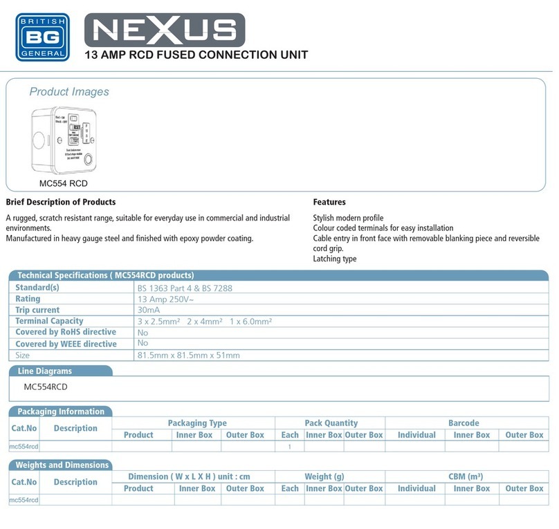
British General NEXUS MC554 RCD Operating instructions

British General

British General NEXUS MC554 RCD Operating instructions

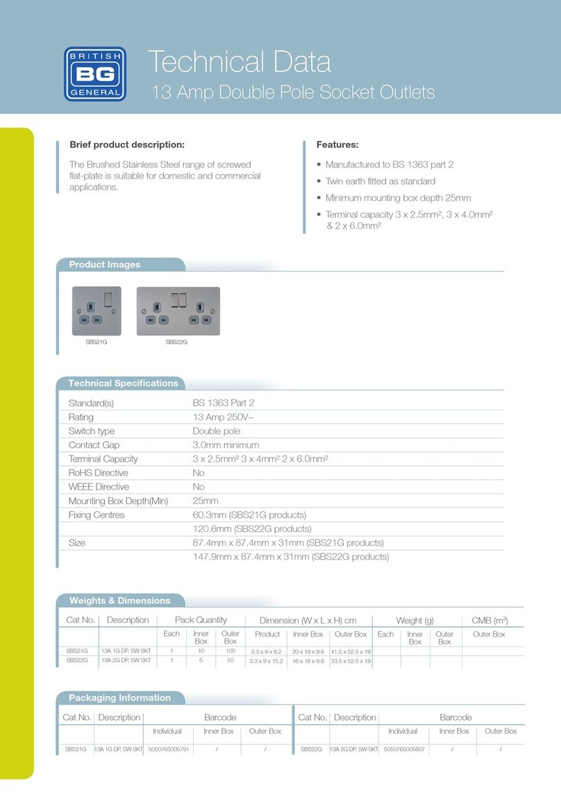
British General SBS21G Instruction manual

British General

British General SBS21G Instruction manual

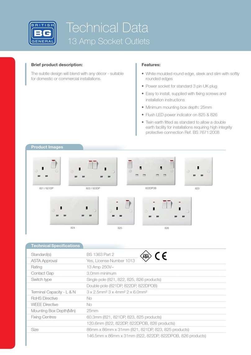
British General 821 Instruction manual

British General

British General 821 Instruction manual

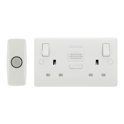
British General Nexus Moulded 822BELL User manual

British General

British General Nexus Moulded 822BELL User manual

British General NBS28G Instruction manual

British General

British General NBS28G Instruction manual

British General PCxx22U3 Series Instruction manual

British General

British General PCxx22U3 Series Instruction manual

Popular Accessories manuals by other brands

Conair SNSC26CTXC manual

Conair

Conair SNSC26CTXC manual

Flexco Flex-Lag Rubber Installation, operation and maintenance manual

Flexco

Flexco Flex-Lag Rubber Installation, operation and maintenance manual

ROSE DISPLAYS ANOQUICK ROUND WITH MULTICLIPS instruction sheet

ROSE DISPLAYS

ROSE DISPLAYS ANOQUICK ROUND WITH MULTICLIPS instruction sheet

Level Pro 300 Series installation manual

Level Pro

Level Pro 300 Series installation manual

Grundfos WIO sensor Installation and operating instructions

Grundfos

Grundfos WIO sensor Installation and operating instructions

Valor APR-101012 Series user guide

Valor

Valor APR-101012 Series user guide

TeraBee TeraRanger Evo Series user manual

TeraBee

TeraBee TeraRanger Evo Series user manual

Lennox 47W36 installation instructions

Lennox

Lennox 47W36 installation instructions

Intra Automation Itabar IBF operating manual

Intra Automation

Intra Automation Itabar IBF operating manual

Chamberlain 915GA install guide

Chamberlain

Chamberlain 915GA install guide

Lightolier AF2FR specification

Lightolier

Lightolier AF2FR specification

MHZ CLASSIC manual

MHZ

MHZ CLASSIC manual

Omron SYSMAC C200H Operation manual

Omron

Omron SYSMAC C200H Operation manual

Cover Pools Save-T Cover II owner's manual

Cover Pools

Cover Pools Save-T Cover II owner's manual

daviteq WSSFC-V1A-025 manual

daviteq

daviteq WSSFC-V1A-025 manual

Jorjin MM5D91-00 installation guide

Jorjin

Jorjin MM5D91-00 installation guide

Furman AIS-10E instruction sheet

Furman

Furman AIS-10E instruction sheet

SCE ENVIRO-THERM SCE-TE170B24VSS user manual

SCE

SCE ENVIRO-THERM SCE-TE170B24VSS user manual

manuals.online logo
manuals.online logoBrands
  • About & Mission
  • Contact us
  • Privacy Policy
  • Terms and Conditions

Copyright 2025 Manuals.Online. All Rights Reserved.