Switched Socket Outlets with USB charger
Installation Information
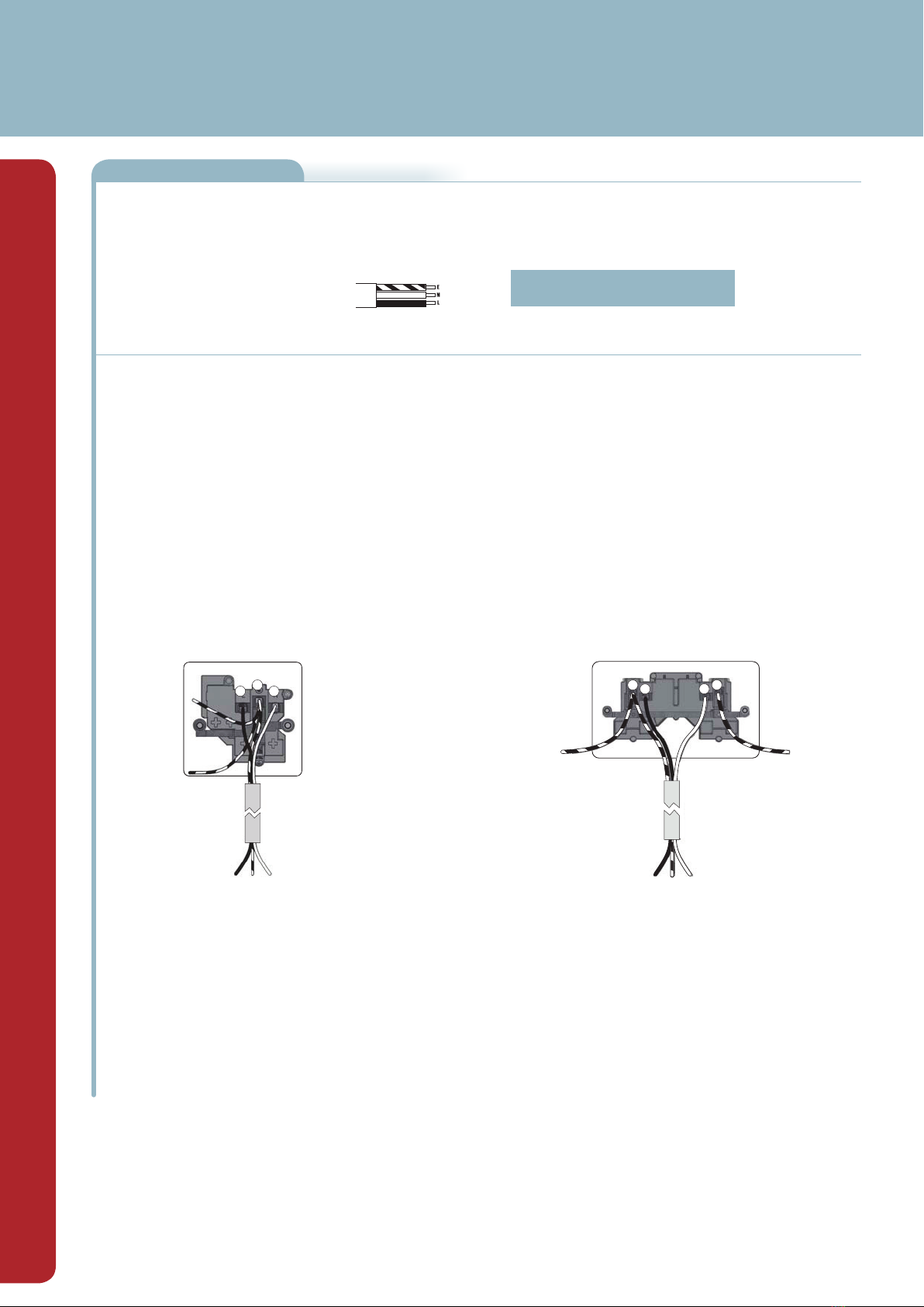
L
EE
N
FROM SUPPLY
TO FUNCTIONAL EARTH
LIVE EARTH NEUTRAL
All earth wires must be
sleeved and terminated
to the back box
1 Gang 13 Amp Switched Socket
This socket is fitted with with two linked terminals to provide a dual earth facility. This is
for use in "clean earth" installations where additional earth capacity is required to comply
with Regulation 607 of BS7671 IEE Wiring Regulations.
Connect the cables as shown in the diagram.
USB Charger Information
Switched 13A socket with 2 x USB ports for charging mobile devices such as mobile phones, MP3 players and tablets.
2.1A 5V output from the USB outputs
• Total charger output current is 2.1A. This can be delivered from one USB socket or divided between the two as required.
• 2.1A is sufficient power output to charge the majority of USB products.
• A device needing 1.5A would leave the other port at 0.6A, so devices may charge more slowly than with a normal single plug charger.
• The total output current achieved is dictated by the specific device being charged and other external factors, such as the quality of charging cable being used.
• Overload protection for connected devices.
Low energy stand-by mode
• When not in use the USB sockets are in a low energy stand-by mode.
The USB circuits on this socket are designed to withstand insulation resistance tests at 500V. A reading of 0.4m +/-0.05 is typically caused by the USB sockets.
Note - The front surface of this product may become warm in use. This is normal and not cause for concern.
2 Gang 13 Amp Switched Socket
This socket is fitted with with two linked terminals to provide a dual earth facility.
This is for use in "clean earth" installations where additional earth capacity is required to
comply with Regulation 607 of BS7671 IEE Wiring Regulations.
Connect the cables as shown in the diagram.
E
L N
FROM SUPPLY
LIVE EARTH NEUTRAL
All earth wires must be
sleeved and terminated
to the back box
Safety Warning
Before use please read carefully and use in accordance with these safety wiring instructions.
Before commencing any electrical work ensure the supply is switched off at the mains. Either by switching off the consumer unit or by removing the appropriate fuse.
Wiring should be in accordance with the latest edition of the IEE regulations (BS 7671).
Wire Identification – Twin & Earth Cable
EARTH = Green/Yellow Sleeving
NEUTRAL = Black (pre Apr 04) / Blue (after Apr 04)
LIVE = Red (pre Apr 04) / Brown (after Apr 04)
The ends of the individual conductors should have the insulation removed by approx.12mm. Any bare earth conductors should be sleeved to within 12mm of the ends.
(These details are for general information only and conductor lengths may need to be trimmed in certain installations).
Technical Helpline: 03300 249 279
If in doubt consult a competent electrician.
General Installation Instructions
1) If using the new product to replace an old one, note the cable connections and wire up new product in the same way as the old one, with Earthing as stated in these instructions.
2) Ensure the mounting box (metal or patress) for either flush or surface mounting is the appropriate size for the product.
3) Route the cable through the most suitable entry point of the mounting box. If a metal box is used, a protective cable grommet should be used.
4) Cables should be prepared so a sufficient conductor length reaches the terminals. Strip the ends of the individual conductors so that an adequate length enters the terminals.
5) Carefully arrange the wiring to lie along the edges of the product or box, keeping the central area clear.
6) To assist with the correct installation please consult the appropriate wiring diagram on this leaflet.
7) When connecting the new accessory ensure that only the bare end of the wire enters the terminal, and no bare wires are visible.
Always tighten the terminal screws securely, but do not overtighten.
An earth connection should always be made between the mounting box earth terminal, and the accessory earth terminal, where fitted. If this earth wire is bare, it is essential that it is sheathed
with a length of green/yellow sleeving.
8) Carefully position the accessory into the wall box, ensuring that no wires are trapped between the plate and the wall. Do not overtighten the screws. (Fit screw covers + clip-on)
9) Once work has been completed correctly, replace the fuse for the circuit, switch the power back on, and test.
The product is now ready for use.
* Note - If your installation uses a four lug metal mounting box, remove the top and bottom lugs or bend fully back.