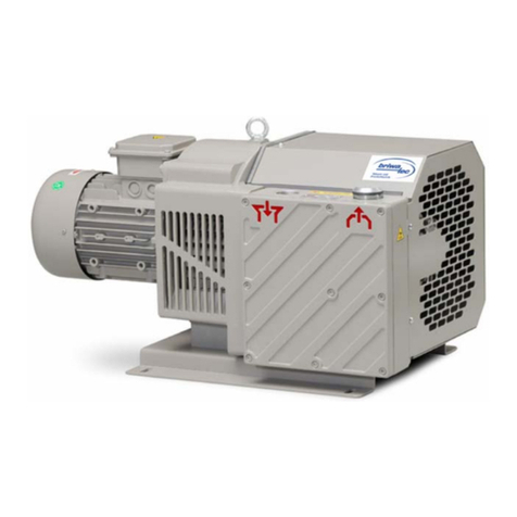
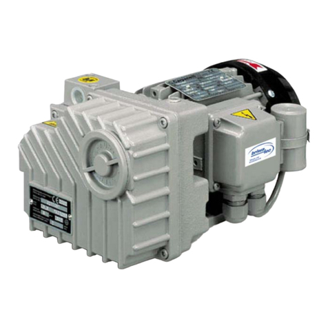
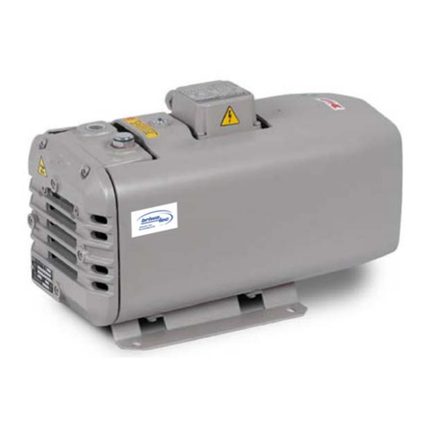
briwatec TOPAS Series User manual

TOPAS
E350V – E600V
Oil flooded rotary vane vacuum pump
Translation of the original instructions
briwatec GmbH
Schönauer Str. 62
79669 Zell i. W.
Germany
Telephone no.: +49 (0) 7625 918 868-0
Fax no.: +49 (0) 7625 918 868 -33
Website: www.briwatec.de
Managing Directors: Markus Britsche, Michael Wagner
District court: Freiburg i. Br. HRB 700368
VAT number.: 11088/10922 Value added tax identification-no.: DE 814 742 383

Contents
B125 06/16 Rev.1 TOPAS E350V-E600V 2
1Contents
1 Contents..............................................................................................2
2 Introduction.........................................................................................3
2.1 Information about the operating manual.........................................3
2.2 Limitation of liability ......................................................................3
2.3 Copyright .....................................................................................3
2.4 Spare parts ..................................................................................4
2.5 Service.........................................................................................4
2.6 CE-Declaration of Conformity .........................................................5
3 Safety .................................................................................................6
3.1 General........................................................................................6
3.2 Description of safety instructions....................................................6
3.3 General safety advice ....................................................................6
3.4 Safety and information signs on the machine ..................................7
3.5 Personnel requirements.................................................................9
3.6 Definition of terms........................................................................9
3.7 Intended use..............................................................................10
3.8 Improper operation .....................................................................11
3.9 Protective measures by the operator/user .....................................11
4 Technical specifications.......................................................................12
4.1 Type plate ..................................................................................12
4.2 Noise emissions ..........................................................................12
5 Functional description.........................................................................13
5.1 Conditions of use ........................................................................13
5.2 Construction...............................................................................14
5.3 Function.....................................................................................15
6 Transport storage ...............................................................................16
6.1 Safety instructions for transport ...................................................16
6.2 Lifting and transporting the machine ............................................16
6.3 Storage......................................................................................16
7 Commissioning...................................................................................17
7.1 Setup.........................................................................................17
7.2 Installation .................................................................................18
7.3 Commissioning ...........................................................................19
8 Operation ..........................................................................................20
9 Maintenance ......................................................................................21
9.1 Air filter (optional) ......................................................................21
9.2 Oil change..................................................................................21
9.3 Changing the oil filter..................................................................23
9.4 Filter element / air de-oiling element ............................................23
9.5 Suction grid................................................................................25
9.6 Coupling ....................................................................................25
9.7 Lip seals.....................................................................................26
9.8 Gas ballast (optional) ..................................................................27
9.9 Automatic oil back-suction ...........................................................27
9.10 Oil level monitoring (optional) ......................................................28
9.11 Maintenance intervals..................................................................29
10 Troubleshooting .................................................................................30
11 Index of figures .................................................................................32

Introduction
B125 06/16 Rev.1 TOPAS E350V-E600V 3
2Introduction
2.1 Information about the operating manual
This manual provides information on how to work with the TOPAS rotary vane
vacuum pumps in the series:
TOPAS E350V to E600V
The prerequisite for safe operation is compliance with all specified safety and op-
erating instructions.
Carefully read the instruction manual before starting work. It is part of the prod-
uct and must be kept in the immediate vicinity of the machine for the operating
and maintenance
personnel at all times.
The company briwatec GmbH assumes no liability for accidents, equipment
damage, loss of production or flow disturbances that have arisen due to
the failure to observe the operating instructions.
In addition, the local health and safety regulations and general safety rules for
the operation of the machine must be observed.
The illustrations are used to promote fundamental understanding and may differ
from the actual execution of the machine.
Components from other suppliers have their own guidelines and safety regula-
tions. They must also be respected.
2.2 Limitation of liability
All information and advice in these instructions has been compiled in accordance
with current standards and regulations, the state of technology and our
knowledge and experience.
The company briwatec GmbH assumes no liability for damage due to:
Failure to follow the instructions
Improper use
Use of untrained staff
Use of spare parts that were not released by the company briwatec GmbH.
Unauthorized changes to the machine or equipment (supplied by briwatec
GmbH)
The agreed contract obligations, general terms and conditions and the delivery
conditions from briwatec GmbH apply, as well as the valid legal regulations at the
time of signing the contract.
We reserve the right to make technical changes in the context of improving the
performance characteristics and further development.
2.3 Copyright
The transfer of these operating instructions to third parties without written ap-
proval from briwatec Ltd. is prohibited.
NOTE!
All content, texts, drawings, pictures and other images are copyrighted and are
protected by intellectual property rights.
Any improper use is punishable by law.
Read the instruction
manual!
Observe the operating
instructions!

Introduction
B125 06/16 Rev.1 TOPAS E350V-E600V 4
Reproduction in any shape or form - even in part - and the use and / or commu-
nication of content without a written declaration from briwatec GmbH is not per-
mitted..
2.4 Spare parts
The company briwatec GmbH recommends the use of original spare parts. Origi-
nal spare parts have special qualities that ensure a reliable and safe operation:
Development for the specific use of the device
High-quality manufacturing
Warranty period of 12 months after installation or shipping
(excluding wearing parts) or other agreements made
NOTE!
The use of non-original replacement parts may change the characteristics of
the machine and compromise safety.
Any liability of the company briwatec GmbH is excluded for damage resulting
from this.
DISPOSAL!
Wearing parts (in the spare parts list) are hazardous waste.
After replacement, wearing parts must be disposed of according to national
laws.
2.5 Service
For service questions, please contact the company briwatec GmbH as follows:
briwatec GmbH
Tel.: +49 (0) 7625 918 868-0
Fax. +49 (0) 7625 918 868 -33
Schönauer Str. 62
79669 Zell i. W.
Germany
www.briwatec.de
For faster processing of your requests, we ask you to have the following data and
information ready in advance:
Serial Number
What actions have already been taken?
For service work on site, the motor must be disconnected from the network by a
qualified electrician, so that an accidental startup cannot take place.
For maintenance, we recommend using the manufacturer, its agents or contrac-
tors especially if it is a question of warranty repairs.
The address of your local service centre can be obtained from the manufacturer
(see manufacturer's address). After repair and before restarting, the measures
listed under "Installation" and "Startup" must be performed as after the initial
startup.
Servicing:

Introduction
B125 06/16 Rev.1 TOPAS E350V-E600V 5
2.6 CE-Declaration of Conformity
Fig. 1 CE-Declaration of Conformity

Safety
B125 06/16 Rev.1 TOPAS E350V-E600V 6
3Safety
3.1 General
The TOPAS rotary vane vacuum pump that are reliably designed, manufactured
and tested based on the latest state of the art have left the factory in perfect
condition. Nevertheless, the machinery may cause risks to people and material
objects when it is operated improperly.
The instructions must therefore be read in full and the safety instructions must be
followed.
Information attached directly to the machine must be respected and maintained
in a legible condition. This applies to:
Identifiers of connections
Data and motor data plate
Information and warning signs
In the event of use that deviates from the proper and intended use, all liability
and warranty will be rejected by the company briwatec GmbH.
3.2 Description of safety instructions
Safety instructions refer to specific hazards. They are marked by symbols in this
manual.
There are four principles that must be considered in the design of safety infor-
mation:
Severity of the risk (signal word)
Type and source of danger (description)
Result of failure to comply
Prevention (measures to prevent the hazard)
The appropriate warning sign is used to mark the area of risk.
Example structure of a safety warning:
DANGER!
Description of the nature and source of the danger!
Description of the consequences of ignoring the danger.
Measures and instructions to avoid danger.
3.3 General safety advice
The following general safety precautions are applied according to the nature of
the hazard:
DANGER!
Indicates an imminently hazardous situation which leads to death
or serious injury if not avoided.

Safety
B125 06/16 Rev.1 TOPAS E350V-E600V 7
WARNING!
Indicates a potentially hazardous situation that can result in death or serious
injury if not avoided.
CAUTION!
Indicates a potentially hazardous situation that can lead to minor
injuries or property damage if not avoided.
The following additional information is used in these instructions:
NOTE!
This symbol indicates an important fact.
It provides valuable information about installation, use or maintenance.
RECYCLING
This symbol indicates useful information for disposal.
Materials are separated and disposed of separately.
In addition, the requirements for the disposal of lubricants (oils and fats) and
other additives are to be considered.
3.4 Safety and information signs on the machine
On top of the machine is a label showing the safety and information signs used.
Fig. 2 Safety and information sign

Safety
B125 06/16 Rev.1 TOPAS E350V-E600V 8
The symbols placed on the machine refer to the risks and prohibitions explained
below. The safety information and recommendations must always be fol-
lowed and you must act prudently to prevent accidents involving personal injury
and property damage!
WEAR HEARING PROTECTION!
Mandatory use of noise protection (ISO 3864 / EN 61 310-1)!
READ THE INSTRUCTIONS FOR USE!
Mandatory reading of the instructions for use (ISO 7000-0419)!
PROHIBITED!
Protective grids and safety devices must not be removed!
WARNING!
Danger of death due to electricity!
Indicates a potentially hazardous situation which can result in
death or serious injury from electrical shock, if not avoided!
WARNING!
Outlet of hot or dangerous gases!
HOT SURFACE!
Indicates a potentially hazardous situation which can result in
death or serious injury from burns on hot surfaces, if not avoided!
WARNING!
Beware of low temperatures (EN 61 310-1)!

Safety
B125 06/16 Rev.1 TOPAS E350V-E600V 9
WARNING!
Maintenance work in progress (read instructions!)
WARNING!
Parts or circuits under high pressure!
WARNING!
The unit is remote controlled and may start up without a warning
signal (ISO 7000-0017)!
3.5 Personnel requirements
WARNING!
Danger due to inadequate qualifications.
Improper operation may result in considerable personal injury and material
damage. Therefore:
All activities must only be carried out by qualified personnel.
Work on electrical equipment must be performed by a qualified electrician in
accordance with electrical regulations.
This relates to work on the electrical system for installation, commissioning, re-
pairs and maintenance.
The operation of the machine must only be performed by trained or skilled per-
sonnel. The operator must be familiar with the basic regulations on occupational
safety and accident prevention and must be familiar and trained in the operation
of the machine. . Before switching on the machine, the user must have read and
understood this manual.
3.6 Definition of terms
… have been informed by the operator in a briefing about the tasks and potential
hazards of improper conduct.
… are, through technical training, knowledge, experience and knowledge of the
relevant provisions, in a position to execute their assigned tasks and identify and
prevent potential hazards independently.
… pre-wired combination of pump and motor.
… drive motor of the pump.
… machine for generating an underpressure (vacuum).
Electrical equipment
Operation of the machine
Trained persons /
operators
Skilled personnel
Machine
Moto
r
V
acuum pump

Safety
B125 06/16 Rev.1 TOPAS E350V-E600V 10
… Construction and operating principle of the machine.
… Volume flow of a vacuum pump in relation to the condition in the suction con-
nection.
… the maximum vacuum that a pump achieves with a closed suction opening, indi-
cated as absolute pressure.
… the vacuum and suction pressure area in which the pump works in continuous
operation. The permanent vacuum and suction pressure is ≥than the final vacuum
and < than atmospheric pressure.
… the noise emitted in a specific load condition indicated as a numeric value,
sound pressure level dB(A) according to EN ISO 3744.
3.7 Intended use
The machine has been designed and constructed exclusively for the appropriate
purpose of use described in this document.
The machine may only be operated in use areas that are described in the instruc-
tions for use:
Only operate the machine in a technically perfect condition.
Do not operate the machine in a partially assembled condition.
The machine must only be operated at ambient temperature and suction
temperature between 12 ° and 40 ° C. At temperatures outside this range,
please contact us.
The machine may be used to convey, compress or suction the following media:
Air,
The suctioned air may contain water vapour, but no water and other fluids;
for water vapour tolerance, see Info D240,
All non-explosive, non-combustible, non-aggressive and non-toxic dry gases
and gas-air mixtures.
WARNING!
Risk of improper use.
Any use of the machine beyond the intended use and / or other use of the
machine can lead to dangerous situations.
TOPAS rotary vane vacuum pumps must only be used as intended.
All information in the instructions must be strictly complied with.
Any claims for damage due to improper use are excluded. For any damage due to
improper use, repairs are under the sole responsibility of the operator.
Rotary vane
Suction powe
r
Final pressure (absolute)
Permanent vacuum
Noise emissions

Safety
B125 06/16 Rev.1 TOPAS E350V-E600V 11
3.8 Improper operation
Misuse may result from the following circumstances:
Suctioning, conveying and compressing explosive, combustible, aggressive
or toxic media, e.g. dust according to ATEX zones 20-22, solvents and
gaseous oxygen and other oxidants.
The use of the machine in non-commercial premises, assuming that the
necessary precautions and protective measures are not taken on the
premises.
Installation in hazardous environments.
The use of the machine in areas with ionising radiation.
Counterpressures on the outlet side exceeding + 0.1 bar.
Modifications to the machine and accessories.
3.9 Protective measures by the operator/user
The machine is used in the commercial / industrial sector. The operator of the
machine is therefore subject to the legal obligations regarding occupational safe-
ty. In addition to the safety instructions in this manual, the safety, accident pre-
vention and environmental protection regulations applicable to the machine’s field
of use must be observed
This applies in particular to the following:
Hot parts of the machine must not be accessible in operation or provided
with protection against being touched.
No people may be endangered by the free suction or ejection of the fluids.
Dangers from electrical energy are excluded.
The operator must be aware of the applicable safety regulations and
conduct a risk assessment to identify additional risks posed by specific
working conditions at the machine’s installation location. This must be
implemented in the form of operating instructions for the operation of the
machine.
The operator must, during the entire operating time of the machine, check
whether the operating instructions provided by him correspond to the latest
regulations and adapt them when necessary.
The operator has the responsibility for installation, operation,
troubleshooting and maintenance, and the setting of clear rules.
The operator must ensure that all employees who work with the machine
have read and understood this manual. He must also conduct training for
personnel at regular intervals and inform them about the dangers.
DANGER!
Ensure risk-free access to the controls.
If the controls have been moved and are not accessible, there is a risk of
injury, including fatal injury.
Do not move the controls and ensure safe access to them.
Furthermore, the operator is responsible for ensuring that the machine is always
in perfect working condition.

Technical specifications
B125 06/16 Rev.1 TOPAS E350V-E600V 12
4Technical specifications
4.1 Type plate
The type plate shows the main technical specifications of the device.
For technical service consultations, the type description, year of manufacture and
serial number must be available.
Fig. 3 Type plate
4.2 Noise emissions
The following noise emissions were determined for operation at 50/60 Hz:
Type
Average sounds pressure level [dB(A)]
50 Hz 60 Hz
TOPAS E350V 75 76
TOPAS E400V 75 77
TOPAS E500V 75 77
TOPAS E600V 76 78
The values were calculated on the basis of DIN EN ISO 3744 ± 3 dB (A)

Functional description
B125 06/16 Rev.1 TOPAS E350V-E600V 13
5Functional description
5.1 Conditions of use
The TOPAS E350V – E600V vacuum pumps are designed for use in the commer-
cial sector. The safety equipment corresponds to DIN EN 13857 Table 4.
The TOPAS E350V – E600V is suitable for the evacuation of closed systems or for
a permanent vacuum in the range of 0.5 – 800 mbar (absolute)
For continuous operation outside of these ranges, there is a risk of oil loss
through the outlet opening.
NOTE!
In application cases in which an unplanned shutdown or failure of the vacuum
pump can cause harm to persons or equipment, appropriate safety measures
must be taken on the equipment side.
The dependency of the suction power on the suction pressure is type-specific and
can be taken from the corresponding datasheets:
Datasheet no. Series
n.n TOPAS E350V
D186 TOPAS E400V
D187 TOPAS E500V
D188 TOPAS E600V
The suctioned air may contain water vapour, but no water and other fluids. Ag-
gressive or combustible gases and vapours may not be suctioned. No hazardous
additives (e.g. combustible or explosive gases or vapours) or aggressive gases
may be suctioned.
Operation in rooms with an explosion risk is not permitted.
The ambient temperature must be between 12°C and 40°C, and the suction tem-
perature must be between 5°C and 40°C. For temperatures outside of this range,
the manufacturer should be consulted.
Counterpressures on the outlet side are only permitted up to + 0.1 bar.
NOTE!
With increased activation frequency (in regular periods of some 10 per hour)
and/or increased surrounding or suction temperature the upper limit for the
motor coil and the bearings may be exceeded.
In such cases please consult the manufacturer.
If mounted outside the aggregate must be protected from environment
influences (i.e. a protective roof).
Suction power, suction
pressure
Suctioned materials:

Functional description
B125 06/16 Rev.1 TOPAS E350V-E600V 14
5.2 Construction
The TOPAS rotary vane vacuum pump consists of the following major compo-
nents:
Fig. 4 TOPAS main components
1. Oil filling point
2. Vacuum connection
3. Exhaust air outlet
4. Oil drain valve
5. Oil sight glass
6. Connection for starting discharge (option with magnetic valve)
7. Cooling air inlet
8. Cooling air inlet
9. Motor with direction of rotation arrow
10. Oil filter

Functional description
B125 06/16 Rev.1 TOPAS E350V-E600V 15
5.3 Function
The pumps of the TOPAS E350V – E600V series are oil-flooded rotary vane
vacuum pumps.
Fig. 5 TOPAS functional diagram
TOPAS E350V – E600V have an oil mist filter on the outlet side. The motor
ventilator cools the motor. The motor and pump are connected via a coupling.
When necessary, a vacuum regulating valve, additional check valve, vacuum-tight
suction filter, fluid separator, tube connection, motor circuit breaker and unloader.
The suctioned medium (air) flows through the suction filter (optional), the pro-
tective grid and then the integrated check valve. The medium fills the suction
area of the pump (1). Through rotation of the rotor, the sliders are pushed
through centrifugal force against the internal wall of the housing, thus forming
three chambers with a consequence of different volumes, which permit the gen-
eration of an underpressure and a flow rate.
(1) Suctioning/start of filling
(2) max. filling volume
(3) compression
During phase (1), the oil for lubrication, compression and cooling is injected. It
can be injected directly or piped in by an oil filter before injection. The medi-
um/oil mixture is conveyed from the housing via the pressure valve to the separa-
tion housing, where the first medium/oil separation occurs.
The medium is de-oiled by the filter element and then flows out of the pump. An
oil back-suction with a float sucks the oil separated through the filter element
back into the pump body.
At the standstill, the integrated suction valve prevents the entry of air, as well as
the sucking back of the oil into the vacuum network. The bypassing of the pres-
sure valve permits a pressure equalization in the housing to the air pressure to
prevent oil collecting in the housing and thus an uneven oil quantity exists on
startup.
A
ccessories:
Mode of operation:

Transport storage
B125 06/16 Rev.1 TOPAS E350V-E600V 16
6Transport storage
6.1 Safety instructions for transport
DANGER!
Danger from suspended load
Risk of injury or death due to falling loads!
Never stand under suspended loads.
Maintain adequate distance to suspended loads.
Ensure stable centre of gravity.
When lifting and transporting the machine, the safety regulations and general
accident prevention regulations and the recognized technical rules must be ob-
served.
6.2 Lifting and transporting the machine
The machine may only be suspended on the designated lifting eye.
The machine may swing out. During lifting, observe the centre of gravity and fol-
low the lifting hoist.
The machinery must be properly packed in its original packaging before being
transported to the destination. The packaging should be attached to a European
pallet or similar so that the machine cannot topple over.
The packaging is intended to protect the individual components prior to assembly
against shipping damage, corrosion and other damage. Therefore, do not destroy
the packaging until just prior to installation.
Before every long transportation, remove the oil from the pump.
ENVIRONMENTAL DAMAGE CAUSED BY IMPROPER DISPOSAL.
Packaging materials are valuable commodities and can often be reused or
prepared for recycling. Therefore:
Dispose of packaging materials in an environmentally safe way.
Observe the local waste disposal regulations; if necessary, use the services
of a specialist disposal company.
6.3 Storage
If the vacuum pump is shut down for a longer period of time (over 3 months) or
the commissioning is delayed, the following measures must be performed:
Empty the pump,
Fill it with corrosion protection oil,
Allow the pump to run for 10 minutes and then drain off the corrosion
protection oil again,
Seal all of the openings with adhesive tape.
Store the pump in a dry location; do not use any rooms which contain
humidity or strong temperature fluctuations.
Observe the acciden
t
prevention regulations!
Packaging

Commissioning
B125 06/16 Rev.1 TOPAS E350V-E600V 17
7Commissioning
7.1 Setup
The oil filling point, oil sight class and oil outlet must be easily accessible. The
cooling air inlet and the cooling air outlets must have a distance of at least 20 cm
from the adjacent walls. Emerging cooling air must not be sucked back in again.
Fig. 4 TOPAS main components
For the components, see Fig. 4 page 14.
Fig. 6 Structural diagram
For maintenance work, a minimum distance of 0.4 m must be observed in front
of the oil filter and the oil reservoir cover; see Fig. 6.
The TOPAS E350V to E600V can only be operated error-free in a horizontal
setup location. The pumps must not be tilted. The setup of the vacuum pump on
solid ground is possible without anchorage. The vibrations from these rotary vane
vacuum pumps are minimal.
In the case of setup on a lower construction, we recommend anchorage via elas-
tic buffer elements. The vacuum pumps are equipped with four rubber shock
absorbers (lower side with threaded hole).
We recommend using these threaded holes for anchoring the pump to a base
frame.
INFORMATION!
For installations higher than 1000 m above sea level, a loss in power is
noticeable.
In this case, we ask for prior consultation with the manufacturer.
A
nchorage

Commissioning
B125 06/16 Rev.1 TOPAS E350V-E600V 18
7.2 Installation
WARNING!
Risk of death by electric shock!
Unprofessional handling of electrical equipment due to lack of skills can lead to
life threatening electric shock.
Electrical installation must only be performed by qualified personnel.
Protection by means of a main switch must be carried out on site.
1. Vacuum connection, item 2 Fig. 4 page 14. The suctioned-out air can be
blown out through the ventilation opening via the air de-oiling element.
INFORMATION!
With too narrow and / or too long lines, the performance of the vacuum pump
is reduced.
The exhaust air opening must not be blocked or obstructed.
2. Fill in lubrication oil (for oil quantity, see Chap. 9.2 page 21) at the oil filling
point (item 1) of the oil reservoir; filling height: middle of oil sight glass (item 5),
then close the filling point.
3. The electrical motor data is indicated on the type plate, chap. 4.1 page 12
and on the motor data plate. The motors comply with DIN EN 60034 and are in
safety class IP 55 and insulation class F. The corresponding connection diagram is
located in the motor terminal box (not needed for the version with a plug
connection). The motor data must be compared with data from the available
power supply (current, voltage, frequency, maximum permitted current).
Fig. 7 Connections to three-phase network
a. Δcircuit (triangle), lower voltage (example: 230・・ V)
b. Y circuit (star), upper voltage (example: 400・・ V)
Standard voltage range
50 Hz 60 Hz
230 / 400 V ± 10%
400 / 690 V ± 10%
265 / 460 V ± 10%
460 ± 10%

Commissioning
B125 06/16 Rev.1 TOPAS E350V-E600V 19
4. Connect the motor and motor protection circuit breaker (for safety, a circuit
breaker, and for strain relief of the connecting cable, a cable gland must be
provided).
We recommend the use of circuit breakers with delayed switch-off according to
over-current conditions. Momentary overcurrent can occur during cold start of the
blower.
7.3 Commissioning
1. Briefly start the motor to check the direction of rotation (item 9, direction of
rotation arrow, Fig. 4 page 14).
2. After possibly correcting the direction of rotation, restart the motor and stop it
again after approx. 2 minutes to refill missing oil according to the oil level in the
sight glass on the filling point.
INFORMATION!
The filling point must not be opened when the pump is running.
3. Connect the suction line.

Operation
B125 06/16 Rev.1 TOPAS E350V-E600V 20
8Operation
The average sound pressure level, measured during 50/60 Hz operation, is indi-
cated in Chap. 4.2 page 12.
We recommend wearing ear protection when working permanently in the vicinity
of the operating pump to prevent damage to hearing.
Despite the most thorough oil mist separation by the air de-oiling element, the
exhaust air still contains small residues of oil aerosols which can be detected by
their odour. Long-term breathing of these aerosols could be hazardous to health.
Therefore, you must ensure good ventilation of the installation room.
HOT SURFACE!
Surface temperatures over 70 ° C. In the hot operating state, the surface
temperatures of components can increase to above 70 ° C. Risk of burns!
Avoid touching the components.
Wear protective gloves.
Before starting operation, the correct installation of the machine, the installation
and commissioning (test run) must be ensured.
Store the pump in a dry location; do not use any rooms which contain humidity
or strong temperature fluctuations.
See chapter 7 “Commissioning” on page 17.
Check the machine before operating to ensure the observance of the
recommended maintenance.
Noise emissions:
Oil aerosols in exhaust air:
This manual suits for next models
4
Table of contents
Other briwatec Water Pump manuals
Popular Water Pump manuals by other brands

Care Fusion
Care Fusion Alaris PK Plus MK4 8005PK201 Directions for use

Versa-Matic
Versa-Matic E1 Service & operating manual

Little Giant
Little Giant 5MSP-WG quick start guide

FLORABEST
FLORABEST FRP 350 C2 translation of original operation manual

i-MO
i-MO *G3D-250 instruction manual

WaterAce
WaterAce R33SU-01 owner's manual