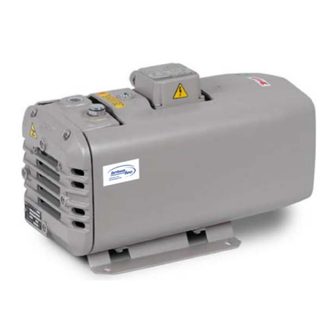
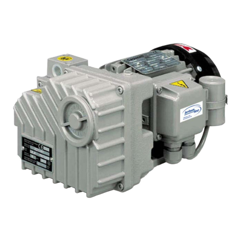
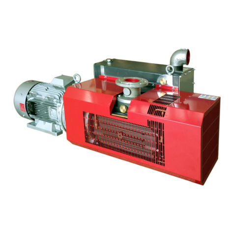
briwatec ZIRKON D060 V Operating and installation instructions

B109 06/16 Rev.2 ZIRKON D060 V – D140 V 1
ZIRKON
D060 V – D140 V
Dry operating rotary vane vacuum pump
Translation of the original instructions
briwatec GmbH
Schönauer Str. 62
79669 Zell i. W.
Germany
Tel. +49 (0) 7625 918 868-0
Fax. +49 (0) 7625 918 868-33
www.briwatec.de
Geschäftsführer: Markus Britsche, Michael Wagner
Amtsgericht: Freiburg i. Br. HRB 700368
Steuer-Nr.: 11088/10922 USt-Id-Nr.: DE 814 742 383

Contents
B109 06/16 Rev.2 ZIRKON D060 V – D140 V 2
1Contents
1Contents ........................................................................................................ 2
2Introduction ................................................................................................... 3
2.1Information relating to the operating instructions ................................ 3
2.2Limited liability .................................................................................. 3
2.3Copywrite.......................................................................................... 3
2.4Spare Parts ....................................................................................... 4
2.5Servicing ........................................................................................... 4
2.6EC-Declaration of Conformity.............................................................. 5
3Safety ............................................................................................................ 6
3.1General ............................................................................................. 6
3.2Description of safety instructions ........................................................ 6
3.3General safety instructions ................................................................. 6
3.4Personnel Requirements..................................................................... 7
3.5Definitions......................................................................................... 8
3.6Prescribed Operation.......................................................................... 8
3.7Non-prescribed operations ................................................................. 9
3.8Safety measures by the operator/user ................................................ 9
4Technical data ...............................................................................................10
4.1Model (type) plate ............................................................................10
4.2Technical Information .......................................................................10
5Operating procedures ...................................................................................11
5.1Start-up conditions ...........................................................................11
5.2Construction.....................................................................................12
5.3Function...........................................................................................12
6Transport storage ..........................................................................................13
6.1Safety instructions during transport ...................................................13
6.2Lifting and transporting the machinery...............................................13
6.3Storage ............................................................................................13
7Start-up ........................................................................................................14
7.1Assembly .........................................................................................14
7.2Installation .......................................................................................14
7.3Start-up ...........................................................................................16
8Operation......................................................................................................17
9Maintenance..................................................................................................18
9.1Air Filter ...........................................................................................18
9.2Discs................................................................................................20
10Fault diagnosis ..............................................................................................22

Introduction
B109 06/16 Rev.2 ZIRKON D060 V – D140 V 3
2Introduction
2.1 Information relating to the operating instructions
These instructions describe the handling of the dry-operating ZIRKON rotary vane
compressor of the series type:
ZIRKON D060 V to D140 V
A condition for secure operation is adherence to all safety and operating instructions.
The operating instructions must be carefully read through before commencement of
any operation! They are an integral part of the equipment and must at all times be
kept in close proximity to the machinery for immediate use by the operating and
maintenance personnel.
The company ‘briwatec GmbH‘ will not be held liable for workplace accidents, damage
to the equipment, production losses or completion disorders that occur as a result of
non-observance of the operating instructions.
Furthermore, the local accident-avoidance directions and general safety regulations in
respect of the operation of machinery will apply.
The figures serve for a general understanding of the machinery and may differ
somewhat from the actual construction thereof.
Components produced by other suppliers have their own safety instructions and
guidelines. These must also be observed.
2.2 Limited liability
All data and directions in this introduction have been assembled with due consideration
of the corresponding norms and regulations, of the state of the art as well as of our
own knowledge and experience.
The company ‘briwatec GmbH‘ will not be held liable for damages due to:
Non-observance of the operating directions
Misuse of equipment
Employment of unqualified personnel
Use of spare parts that have not been provided by the company ‘briwatec GmbH‘
Arbitrary alteration of machinery components or of accessories (supply list from
the company ‘briwatec GmbH‘)
The responsibilities agreed in the supply contract, the general commercial conditions
as well as the conditions of supply by the company ‘briwatec GmbH‘ , and the
regulations current at the time of signing of the contract will apply.
We reserve the right to make technical changes with a view to improving the operating
conditions and further development.
2.3 Copywrite
The transfer of the operating instructions to third parties without written permission
from the company ‘briwatec GmbH‘ is prohibited.
NOTICE!
A
ll data contained herein, texts, drawings, pictures and other illustrations are protected by
copy wri
t
e and are subject to commercial patent rights.
A
ll misuse thereof is liable to prosecution!
Duplication in any type or form – even extracts – as well as the utilization and/or
communication of the contents hereof are not permitted without written authorization
by the company ‘briwatec GmbH‘ .
Read the operating
instructions!
Observe the operating
instructions!

Introduction
B109 06/16 Rev.2 ZIRKON D060 V – D140 V 4
2.4 Spare Parts
The company ‘briwatec GmbH‘ recommends the use of original spare parts. Original
spare parts possess special quality properties and provide reliable and safe
functionality;
Development of the special use of the equipment
Manufacture in high quality and value
12-Months guarantee after installation or shipment (other than
worn-out components) or other agreed conditions.
NOTICE!
T
he use of non-original spare parts can alter the properties of the equipment and put its
safety at risk!
T
he company ‘briwatec GmbH‘ is absolved of any liability for dama
g
e that results
therefrom.
DISPOSAL!
Worn-out components (indicated in the spare parts list) are waste products.
A
fter exchan
g
e, the worn-out components should be disposed of in accordance with the
national re
g
ulations.
2.5 Servicing
For servicing queries, the company ‘briwatec GmbH‘ can be contacted as follows:
briwatec GmbH Tel. +49 (0) 7625 918 868-0
Schönauer Str. 62 Fax. +49 (0) 7625 918 868-33
Germany www.briwatec.de
For faster response to your queries, please have available the following data and
information:
Serial number
Which activity has already been undertaken?
Prior to service works on-site, the motor has to be disconnected from the circuit by a
qualified electrician so that an unforeseen start does not occur.
For servicing work, we recommend that the manufacturer or its local branch or sub-
contractor be engaged, especially where possible repairs under warranty are involved.
The address of the servicing station appropriate for yourselves can be obtained from
the manufacturer (see the manufacturer’s address). Following a repair or prior to re-
start-up, the jobs indicated under “Installation“ and “Start-up“ must be carried out as
for the initial start-up procedure.
Service work:

Introduction
B109 06/16 Rev.2 ZIRKON D060 V – D140 V 5
2.6 EC-Declaration of Conformity
Figure 1 CE-Declaration of Conformity

Safety
B109 06/16 Rev.2 ZIRKON D060 V – D140 V 6
3Safety
3.1 General
The ZIRKON rotary vane vacuum pump has been constructed, completed and tested in
accordance with the safety guidelines of the latest state of the art, and has been
released in a technically safe and impeccable condition. Nevertheless, dangers can occur
with use of the machinery, for persons and objects, if it is used in an improper manner.
The operating instructions must be read comprehensively and the safety directions must
be adhered to.
The operating directions that are attached to the machinery must be followed and must
be kept in a readily readable condition. This relates, for example, to:
Connection indicator
Data and motor identification plate
Instructions and warning plates
In the event of non-conforming operation, all liabilities and warranties on the part of the
company briwatec GmbH are rescinded.
3.2 Description of safety instructions
Safety instructions refer to particular dangers. These are indicated in this guide book by
way of symbols.
SAFE refers to 4 basics in the description of the safety instructions:
Severity of danger (Signal word)
Type and origin of the danger (description)
Consequence of non-observance
Avoidance (measures to avoid a danger)
The corresponding warning symbol serves to identify the point of danger.
Model construction of safety directions:
DANGER!
DESCRIPTION OF THE TYPE AND ORIGIN OF THE DANGER!
Measures taken to avoid the danger
3.3 General safety instructions
The following general safety instructions are used according to the type of danger:
DANGER!
Refers to an immediate, dan
g
erous situation that results in death or serious injury if not
avoided.

Safety
B109 06/16 Rev.2 ZIRKON D060 V – D140 V 7
WARNING!
Refers to a possibly dan
g
erous situation that could lead to death or serious in
j
ury, if not
avoided.
CAUTION!
Refers to a possibly dan
g
erous situation that could lead to sli
g
ht or minor in
j
ury or to
dama
g
e of ob
j
ects if not avoided.
The following indicators are used in this guide book:
INDICATOR!
T
his symbol refers to an important state of affairs.
Relevant instructions for the installation, operation or maintenance are provided.
RECYCLING!
T
his symbol refers to relevant instructions for disposal.
Materials must be separated and disposed of individually.
Similarly, the instructions for the disposal of lubricants (oils and
g
reases) as well as of
additives must be observed!
3.4 Personnel Requirements
WARNING!
Dan
g
er from inadequately qualified personnel
Inappropriate actions can lead to serious personnel injury and material damage.
T
herefore:
All operations must be permitted to be undertaken only by qualified personnel!
Electrical installations Work with electrical installations may only be undertaken by expert electricians in
accordance with electro-technical regulations.
This refers to work on the installation, operation, repair to and maintenance of
electrical equipment.
Operation of the machinery Operation of the machinery may only be undertaken by trained or instructed
personnel. The operator must be conversant with the basic directions regarding safety
at work and accident avoidance, and must have been trained in the management of
the machinery. The operator must have read and understood the operating
instructions prior to start-up of the machinery.

Safety
B109 06/16 Rev.2 ZIRKON D060 V – D140 V 8
3.5 Definitions
… Trained Personnel/Operators have been trained by the operator in regard to the
tasks given to him and the possible dangers from inappropriate actions.
… Qualified Personnel because of their technical training, knowledge and experience as
well as their knowledge of the appropriate directions, are capable of carrying out the
tasks given to them and able to identify dangers and how to avoid them.
... connection-ready combination of the pump housing, rotor and motor.
... Driving motor of the vacuum pump.
… machine for generating an under pressure (vacuum).
… Volume flow of a vacuum pump in relation to the condition in the suction
connection.
… the maximum vacuum that a pump achieves with a closed suction opening, indicated
as absolute pressure.
... The vacuum or suction pressure area, which operates the pump in continuous
operation. The permanent vacuum and suction pressure is ≥than the final vacuum
and < than atmospheric pressure.
… The given noise at any particular load condition as numerical value, the noise level in
dB(A) in accordance with EN ISO 3744.
3.6 Prescribed Operation
The ZIRKON V series machines are suitable for evacuation of closed systems, or for a
permanent vacuum in the intake pressure range 120 to 1000 mbar (abs). These dry
operating vacuum pumps are suitable for pumping air with a relative humidity of 30 to
90%.
The machine may only be operated in the following manner:
Only when the machine is operated in a technically faultless condition
When the machine is not in a partially assembled condition
When the machine is in an ambient temperature and suction temperature
between 5and 40 C. At temperatures outside this range please refer to the
supplier.
The machine can be used in the following media:
Air having a relative humidity of 30% to a maximum of 90%,
Dry, non-aggressive gases.
WARNING!
Dan
g
er when used in non-prescribed manner!
A
ny use of the machinery that is outside and/or alternative to the prescribed manner can
lead to dan
g
erous situations.
ZIRKON rotary vane vacuum pumps must only be used as intended.
All instructions in the operating manual should be strictly adhered to.
Claims of any kind in respect of damage due to non-prescribed use are not permitted.
The operator alone is liable for damage due to non-prescribed use.
Trained persons / operators
Skilled personnel
Machinery
Motor
Vacuum pump
Suction power
Final pressure
(absolute)
Permanent vacuum
Noise emission

Safety
B109 06/16 Rev.2 ZIRKON D060 V – D140 V 9
3.7 Non-prescribed operations
Mis-usage can result from the following methods of operation:
No dangerous substances may be sucked into the machine such, for example, as:
° combustible or explosive gases or fumes,
° steam,
° aggressive gasses.
The use of the machine in non-industrial establishments, in which the necessary
precautions and safety measures have not been undertaken.
The installation in explosion-prone environments.
Alterations to the machinery and its component accessories.
3.8 Safety measures by the operator/user
The machine is operated in commercial/industrial situations. The operator of the
machine is, therefore, subject to the legal requirements in respect of working safety.
In addition to the safety regulations stated in this operating manual, the applicable
safety-, accident- and environmental protection regulations must be adhered to for
operation of this machinery.
In this regard, it should be specially noted that:
Hot parts of the machine must not be accessible or be provided with protective
contact means.
Personnel should not be placed in danger from free suction or expulsion of medium
substances.
Danger from electrical energy should be prevented.
The operator must be conversant with the relevant protection-at-work regulations
and must ascertain any situation judged to comprise dangerous conditions when
the work-place of the machinery will have special safety regulations. These should
be available to him as operating instructions for using the machinery.
The operator must undertake tests throughout the operation of the machinery to
check whether the operating instruction being followed by him actually conform to
the prescribed instructions for operating the machinery and, if necessary, modify
accordingly.
The operator must clearly regulate and establish the adequacy of the installation,
operation, fault removal and maintenance.
The operator must ensure that all co-workers involved in operation of the
machinery have read and understand these operating instructions. In addition, he
must subject the personnel to training sessions at regular intervals and keep them
informed about dangers.
DANGER!
Safe access to the operatin
g
components!
If operatin
g
components are displaced and unreachable, there is the risk of injury and life-
threatenin
g
in
j
ury.
Operating components should not be displaced and safe access should be available.
In addition, the operator is responsible for ensuring that the machinery is permanently
in a faultless technical condition.

Technical data
B109 06/16 Rev.2 ZIRKON D060 V – D140 V 10
4Technical data
4.1 Model (type) plate
The model plate contains the relevant technical information about the machine.
In the event of technical service queries the model references, date of manufacture
and serial number must be available.
Figure 2 Type plate (example)
The highest permitted flow volume and vacuum are dependent upon the size of
construction and are indicated on the model plate.
4.2 Technical Information
The following technical details and noise emissions apply to the ZIRKON V series:
Figure 3 ZIRKON V series, Technical Information
The flow volume with free passage comprises 60, 80, 100 and 140 m3 /h at 50Hz
operation. The dependence of the pumping capacity of the inlet pressure is shown on
the corresponding data sheets.
The noise pressure level or noise production level according to EN ISO 3744,
measured at 1 m intervals at one operating position at about 2/3 of the permitted
total pressure differential and connected lines without vacuum reduction, are given in
the table of figure 3 as having a tolerance of ±3 dB(A).
Hearing protection ! To prevent hearing damage through lengthy presence in the vicinity of an operating
machine, the use of hearing protection means is recommended.

Operating procedures
B109 06/16 Rev.2 ZIRKON D060 V – D140 V 11
5Operating procedures
5.1 Start-up conditions
The ZIRKON rotary vane vacuum pumps are intended for use in the commercial sector,
i.e. the safety arrangements conform to DIN EN ISO 13857 for persons aged from 14
years
They are suitable for the transport of air having a relative humidity of 30% to a
maximum of 90% and of dry, non-aggressive gases.
The vacuum pump can be operated in continuous vacuum in the intake pressure range
of 120 to 1000 mbar (abs).
The dependency of the suction power on the suction pressure is type-specific and can
be taken from the corresponding datasheets:
Construction series Data page No..
ZIRKON D060 V D138
ZIRKON D080 V D139
ZIRKON D100 V D140
ZIRKON D140 V D141
The suctioned air may contain no water or other fluids. Aggressive or combustible
gases and vapours may not be suctioned. No hazardous additives (e.g. combustible or
explosive gases or vapours) or aggressive gases may be suctioned.
Operation in rooms with an explosion risk is not permitted.
The suction and inlet temperature must be between 5 °C and 40 °C For temperatures
outside of this range, the manufacturer should be consulted.
NOTICE!
A
t increased duty cycles (evenly spaced about 10 times per hour) and elevated ambient
and inlet temperatures, the maximum temperature of the motor winding and the bearings
is exceeded.
In the case of such conditions seek advice from the manufacturer.
In outdoor set ups, the unit must be from protected from environmental influences (e.g.
by means of a shelter).
DANGER!
Unintentional stoppa
g
e or interruption
In the case of an operation in which an unintentional stoppa
g
e of or interruption in the
compressor leads to a risk of in
j
ury to personnel or dama
g
e to equipment, appropria
t
e
safety measures to the equipment must be initiated!
Suction power, suction
pressure
Extracted substances:

Operating procedures
B109 06/16 Rev.2 ZIRKON D060 V – D140 V 12
5.2 Construction
The ZIRKON rotary vane vacuum pump consists of the following major components:
Figure
4 main components of the ZIRKON V
1. Cooling air inlet
2. Direction of rotation arrow
3. Terminal box
4. Connection for suction line (vacuum port)
5. Exhaust port / exhaust silencer
6. Lifting
7. Cooling air inlet
8. Type plate
5.3 Function
The machines of the ZIRCON construction series have a suction side and exhaust side
each with a connection threading (figure 4, positions 4 and 5). The sucked air is
cleaned by passing across a built-in fine filter.
The machine is encased in a sound cover made of tin. A ventilator is situated on the
clutch, through which the cooling takes place.
Accessories For the machinery types of the ZIRKON construction series the following accessories
are available if required:
Vacuum-regulating valve
Check valve
Motor-protection switch
Hose connection
Spare suction filter

Transport storage
B109 06/16 Rev.2 ZIRKON D060 V – D140 V 13
6Transport storage
6.1 Safety instructions during transport
DANGER!
Dan
g
er from swaying loads!
Dan
g
er of in
j
ury and in
j
ury leadin
g
to fatal in
j
ury from fallin
g
loads!
Do not stop under swaying loads
Maintain sufficient distance from swaying loads
Be mindful of the centre of gravity
Be aware of accident When lifting and transporting the machinery be aware of the technical safety regulations
Prevention regulations! and the general accident prevention regulations as well as the accepted regulations of
the state of the art.
6.2 Lifting and transporting the machinery
The machines in the series may only be suspended from the lug provided (see position
6, figure 4).
The machine may swing outwards. Be aware of the centre of gravity when lifting and
follow the lifting instructions!
Packaging The machine must be correctly packed in the original packaging prior to transporting to
its idestination. The package must be fixed on a Europalette or similar system so that
the machine cannot tip over.
The packaging should protect the individual components up to their assembly, from
transportation damage, corrosion and other damage. Therefore, the packaging must
not be disturbed and only removed shortly before assembly.
ENVIRONMENTAL DAMAGE THROUGH DISPOSAL!
Packaging material is a valuable product and can, in many cases, be re-used
or carefully prepared and re-used. Therefore:
The packaging material must be disposed of in an environmentally friendly manner
The local disposal regulations should be observed ; if necessary, a company
qualified in disposal matters should be contracted to do so.
6.3 Storage
The machinery of the construction series ZIRKON must be stored in a dry situation that
has normal air humidity
At a relative humidity above 80% it is recommended that the site is enclosed in a
sealed cover containing a drying agent.
Storage for longer than a year should be avoided.

Start-up
B109 06/16 Rev.2 ZIRKON D060 V – D140 V 14
7Start-up
7.1 Assembly
NOTICE!
A
ll illustrated numbered components refer to the positions in the illustration of fi
g
ure 4 on
pa
g
e 12.
During assembly and construction of the machinery care should be taken to ensure
that the cold-air inlet (position 1) and the cool-air outlet (position 7) are at least 10 cm
away from adjacent walls.
For de-assembly of the filter box cover, cover hood and exhaust screen, 30 cm space
must be available for maintenance work.
Assembly of the ZIRKON can be undertaken on a stable and secure surface without the
need for fixed footings.
For assembly on an under-construction we recommend a fixture having elastic rubber
pads.
Vibration of machines of the ZIRKON construction series is minimal.
NOTICE!
For assembly at levels
g
reater than 1000 metres above sea-level, reduced output is
noticeable.
In this case, we advise prior advice from the manufacturer.
7.2 Installation
WARNING!
Mortal danger from electrical shocks!
Non-professional handling of electrical components can lead to life-threatening electric
shocks, if undertaken with insufficient experience.
Electrical installations should only be undertaken by qualified personnel
Fused security for the construction should be carried out via the main junction box.
1. Vacuum line connection, figure 4, position 4.
The hose must withstand a pressure of 5 kPa (absolute). The diameter of the hose
should be at least the same as the diameter of the inlet flange.
2. The absorbed air can be blown out by the air exhaust or led away through pipe
hose and pipe connections.
NOTICE!
With too narrow and/or lon
g
conduits the output of the machine is reduced!

Start-up
B109 06/16 Rev.2 ZIRKON D060 V – D140 V 15
3. The electrical data is indicated on the type plate (position 8) or on the motor type
plate. The motors conform to DIN EN 60034 and are displayed in Safety type IP 55
and isolation class F. The corresponding connection scheme is displayed in the
junction box of the motor (not present where the circuit has a plug connection). The
motor data should be compared with the existing grid (current type, tension, grid
frequency and permitted current strength).
For information regarding single-phase and triple-phase alternating current as well as
connection siting see below!
4. The motor and motor protection switch (for security a motor protection switch and for
draught exclusion of the connecting cable a cable threading are provided).
NOTICE!
We recommend the use of motor protection switches where switching off is dependent
upon a possible excess current which becomes time-delayed.
Shor
t
-term excess current can occur during a cold start of the compressor!
Triple-phase alternating current:
With triple-phase alternating current three alternating tensions are carried across five
connections that have a timed relationship to one another, a so-called phased
relationship.
Figure 5 Connection of three-phase electrical power
a. ∆- Connection (triangular), lower tension (Example: 230 V)
b. Y – Connection (star-shaped) higher tension (Example 400 V)
Standard Tension Range
50 Hz 60 Hz
220 / 380 V ± 5%
230 / 400 V ± 10%
240 / 415 V ± 5%
265 / 460 V ± 10%
ba

Start-up
B109 06/16 Rev.2 ZIRKON D060 V – D140 V 16
7.3 Start-up
NOTICE!
T
he maximum number of starts per hour may not exceed 10
1. The motor start-up and current direction should be checked with the arrow
direction on the housing, see figure 4, position 2
CAUTION!
T
HE PRESSURE CONDUI
T
MUST NOT BE CONNECTED!
With this star
t
-up the suction line must not be connected. With reverse flow of the
v
acuum pump and connected suction line, a vacuum can build up that can lead to dama
g
e
to the discs and actual fracture of the discs.
2. Connect the pressure conduit at the position 4 in figure 4. Notice: if the vacuum
pump is connected to the generator via a conduit in excess of 3 m in length, we
recommend the inclusion of a non-return valve between the pump and the
conduit. This will avoid reverse flow after shut-down.
3. Vacuum-regulating valve (option). The regulation of the vacuum is carried ouit
by turning the regulation knob; take note of the indicated turning direction.

Operation
B109 06/16 Rev.2 ZIRKON D060 V – D140 V 17
8Operation
Sound emission We recommend that in prolonged presence in the vicinity of the operating vacuum
pump, the operator uses a personal hearing protection device in order to avoid
permanent damage to the hearing organ.
HOT SURFACE!
Surface temperatures in excess of 70°C!
A
t hot operatin
g
temperatures the surface temperatures of components can rise above
70°C. Risk of burns!
Avoid touching the components.
Wear protective gloves.
Before start-up of the operation, the correct set up for the machine, the installation
and start-up (trial run) should be organized.
See chapter 7 “Start-up“ page 14.
The machine should be checked prior to start-up in respect of observance of the
service measures! See chapter 9 “Service“, page 18.

Maintenance
B109 06/16 Rev.2 ZIRKON D060 V – D140 V 18
9Maintenance
DANGER!
Before undertaking maintenance works:
For maintenance activities, the machine must be secured by withdrawal of the circuit
plug or operation of the main switch to separate it from the E-Grid and to ensure against
re-switch-on.
Pressure-conducting conduits must be purged of air before disassembly! Maintenance
must not be carried out on operation-warm machinery (danger of injury through contact
with hot components)!
All machines of the ZIRKON D003 V to D040 V series have a permanent lubrication for
the bearing. This must not be re-lubricated.
For maintenance operations, the discs and the filter cartridge of the air filter must be
checked, see chapter 9.1 and 9.2.
For maintenance of the filter and discs the exhaust screen and casing lid must be
unscrewed.
For this purpose the fixing screws must be withdrawn and the cover / lid removed.
9.1 Air Filter
NOTICE!
In the case of insufficient maintenance of the filter, the power of the vacuum pump is
reduced!
The filter cartridge for the suction air, depending on the degree of contamination,
should be cleaned by purging from inside to outside.
The operational readiness of the degree of separation will be reduced in spite of
cleaning the filter. Therefore, we recommend replacement of the filter every half
year.
Filter replacement:
Filter replacement is carried out in the following manner:
Unscrew the filter box coverfigure 6, position 3
The filter cartridge is withdrawn, figure 6, position 1
The filter cartridge is cleaned and/or exchanged
The re-assembly is carried out in the reverse manner.

Maintenance
B109 06/16 Rev.2 ZIRKON D060 V – D140 V 19
Figure 6 Air box cover, air filter
1. Filter cartridge
2. Filter box lid gasket
3. Airbox cover
Figure 7 Open housing
1. Disc
2.Housing boring
3.Housing lid
4. Disc/housing lid

Maintenance
B109 06/16 Rev.2 ZIRKON D060 V – D140 V 20
9.2 Discs
Disc control mechanism
The machines of the construction series ZIRKON D060 V to D140 V have 4 carbon
discs that wear out during operation by rubbing. In order to achieve faultless
operation, the discs must be checked for wear at regular intervals.
For this purpose the discs are disassembled:
The cover is removed
Housing lid is unscrewed, figure 7 position 3
The discs are removed for checking, figure 7 position 3
Minimum thickness and condition of the discs are checked.
The discs must have the following thickness (A):
Construction series Minimum thickness A
ZIRKON D060 V 36 mm
ZIRKON D080 V 36 mm
ZIRKON D100 V 41 mm
ZIRKON D140 V 41 mm
Figure 8 Disc thickness A
This manual suits for next models
3
Table of contents
Other briwatec Water Pump manuals
Popular Water Pump manuals by other brands

Dover
Dover PSG Wilden PS800 Engineering, operation & maintenance

CET
CET PFP-20HPKHL-1D Instruction handbook

Flexicon
Flexicon PD22I Instruction handbook

Putzmeister
Putzmeister BSA 1006 D5 operating instructions

fluid-o-tech
fluid-o-tech MG Series instruction manual

EasyPro
EasyPro EXP8700-2 Series Installation and service manual

GORMAN-RUPP PUMPS
GORMAN-RUPP PUMPS 4D-X3 3P Installation, operation, and maintenance manual with parts list

moyno
moyno 2000 Service manual

Hozelock
Hozelock 7816 manual

Intex
Intex Quick-Fil AP634 owner's manual

Taconova
Taconova TACOFLOW2 PURE 15 Installation and operating instructions

Oase
Oase AquaAir 250 LM operating instructions