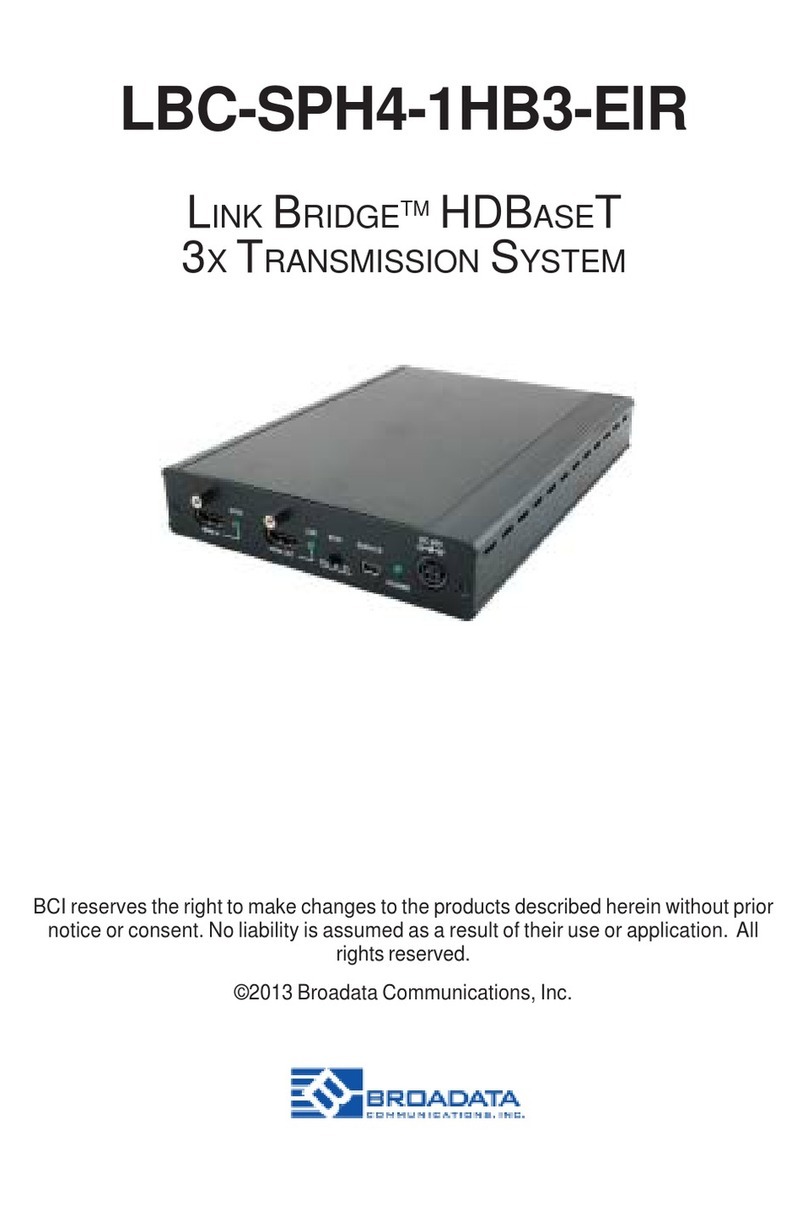
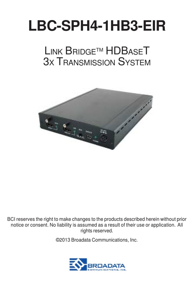
Broadata 1100E Series User manual

1100E Series
FIBER OPTIC
HD-SDIDIGITAL VIDEO
TRANSPORT SYSTEM
BCI reserves the right to make changes to the products described herein without
prior notice or consent. No liability is assumed as a result of their use or
application. All rights reserved.
©2005 Broadata Communications, Inc.

BCI1100EUser’sManual
Fiber Optic HD-SDI Digital Video Transport System
Broadata Technical Support, CustomerService@Broadatacom.com 3
SAFETY INSTRUCTIONS AND
COMPLIANCE DECLARATIONS
PLEASEOBSERVETHEFOLLOWINGSAFETY
PRECAUTIONSASOURPRODUCTS CONTAIN
CLASS I LASER PRODUCTS
WARNING
Do not disconnect the fiber optic connector while the unit is powered
up. Exposure to laser radiation is possible when the laser fiber optic
connector is disconnected while the unit is powered up.
Although the fiber optic connectors in this product emit only Class 1
energythatisbelowthelevelsconsidered to be hazardous, one should
neverstaredirectlyintoafiberopticconnectororanunconnectedfiber
end unless one can be certain that no exposure to laser energy could
occur.
CAUTION
This manual is intended for use by trained service personnel. The use
of controls, making adjustments, or performing operations other than
those specified may result in hazardous radiation exposure.
Thefollowinglabelorequivalentislocatedonthesurfaceoflaserproducts.
Thislabelindicatesthat the product is classified as a CLASS 1 LASER
PRODUCT.
SURGEPROTECTION DEVICERECOMMENDED
This product contains sensitive electrical components that may be
damaged by electrical spikes, surges, electric shock, lightning strikes,
etc. Use of surge protection systems is highly recommended in order
to protect and extend the life of your equipment.

BCI1100E User’sManual
Fiber Optic HD-SDI Digital Video Transport System
Broadata Technical Support, (800) 214-0222
4
TABLE OF CONTENTS
1.0 PRODUCT DESCRIPTION .............................................5
2.0 SETUP..............................................................................7
2.1 MOUNTING......................................................................8
2.2 CABLING AND CONNECTORS .....................................8
2.2.1 ELECTRICAL CABLE CONNECTION .........................8
2.2.1.1 HDTV DIGITAL INTERFACE .....................................8
2.2.2 OPTICAL FIBER CONNECTION...............................10
2.3 DC POWER CONNECTION..........................................11
3.0 OPERATION...................................................................12
4.0 MAINTENANCE AND TROUBLESHOOTING..............13
4.1 MAINTENANCE .............................................................13
4.2 TROUBLESHOOTING ..................................................14
5.0 SPECIFICATIONS..........................................................16
6.0 SERVICE PROCEDURE ...............................................17
6.1 REPLACEMENT POLICY .............................................17
6.2 RETURN AND REPAIR SERVICE.................................17
7.0 LIMITED WARRANTY ....................................................18

BCI1100EUser’sManual
Fiber Optic HD-SDI Digital Video Transport System
Broadata Technical Support, CustomerService@Broadatacom.com 5
1.0 PRODUCT DESCRIPTION
The 1100E Series is a high performance, yet affordable, Fiber Optic
HD-SDI Digital VideoTransport System. The standard 1100E system
is designed to transport one (1) channel SMPTE-292M HD or
SMPTE-259Mserialdigitalvideosignaloverlongdistance througheither
singlemode or multimode fiber. Many versions of optical transmitter
and receiver combinations are available to address different distance
requirements.
Due to the use of advanced digital fiber optic transmission technology,
no user adjustments are required in the 1100E system, enabling quick
setup and trouble-free operation with standard non-reclocking
configuration. The 1100E can handle ATSC, SDI, DVB-ASI, HD, and
many other video formats. One can also choose the reclocking
configurationwhichprovides SMPTE-292M HD,SMPTE-259MSDIand
DVB-ASIsignalregeneration.
The 1100E comes with two packaging options: a rugged, standalone,
and compact unit, or a plug-in card for a card cage system. Panel
connectors are providedfor digital HD-SDI video (BNC connector)and
fiberconnection(FC-typeforthe singlemode version, orST-typeforthe
multimodeversion). The1100E can be easily monitored by front panel
LED indicators for channel activity. Transmitter units provide 1
loop-throughoutputfor monitoring,andthe receiverprovides2 outputfor
monitoringandrecording.
FrontpanelLEDindicators provide power,opticallinkandsignal detect
reclocking status as illustrated in Figure 1-1.

BCI1100E User’sManual
Fiber Optic HD-SDI Digital Video Transport System
Broadata Technical Support, (800) 214-0222
6
Figure 1-1
1100E Front/Rear Panels
DIGITAL
VIDEO
CKOL
OUT2
RXTX 1100E-TRX
HD
PWR
VIDEO
DIGITAL
KLOC
IN
HD
PWR
OUT OUT1
12VDC
VGA

BCI1100EUser’sManual
Fiber Optic HD-SDI Digital Video Transport System
Broadata Technical Support, CustomerService@Broadatacom.com 7
2.0 SETUP
TheBCI1100ESeriesunitsareusedinpairs. Forunidirectionalsystems,
one 1100E transmitter unit is located at the near end and connected to
the1100E receiver located at the far endofthelink,connectedthrough
one optical fiber. Each unit provides a separate electrical interface
connectorforthevariousvideosignals.Forbi-directionalsystems,one
1100Etransceiverunitlocated atthenear endandconnectstoan 1100E
transceiverunitlocatedat thefarendthrough twoorone(WDM models)
fiber. Connections are one to one between the two units. Figure 2-1
depicts two typical installations.
Figure 2-1
1100E Setup

BCI1100E User’sManual
Fiber Optic HD-SDI Digital Video Transport System
Broadata Technical Support, (800) 214-0222
8
2.1 Mounting
Beforeinstallingtheunitsintoyourhousing,makesurethereis
enoughspacetopulland connect boththeelectricalandoptical
cables without stressing them beyond the manufacturer’s
limitations (also known as the bend radius minimum).
2.2 Cabling and Connectors
Inordertosetupthe BCI 1100Eproperly,makesuretoobserve
thefollowinginstructions wheninstallingtheproper cables. The
1100E requires two parts to the cabling setup, the electrical
and the optical. For the optical part, observe the following
procedures,astherearevarious types of opticalconnectorsas
illustratedonthefollowingpage.
2.2.1 Electrical Cable Connection
Fortheelectricalconnection, itisrequiredthat the following
stepsbe observed when connecting the video devices, as
they require special attention. They are described in the
followingsection.
2.2.1.1 HDTV Digital Video Interface
The1100E’sprovideoneBNCconnectorsforvideoinput
ports and two BNC connector for video output ports.
SerialDigitalVideosignal are sentovera75-ohmcoax
cable terminated in a BNC connector (e.g., Belden
1694Aorbetter).Thedatarateis 1.485 Gbps. Use the
followingstepsforconnectingthevideo.

BCI1100EUser’sManual
Fiber Optic HD-SDI Digital Video Transport System
Broadata Technical Support, CustomerService@Broadatacom.com 9
Proceedwiththefollowingsetupwhenconnectingthe
videosourcesandreceiverstothe1100E.
1. Connect the user’s serial digital video source to
the digital video IN connector on the 1100E
transmitter unit.
2. Connect the digital video OUT or/and BNC
connectorsonthe1100Ereceiverunitto theuser’s
digitalvideo monitor.
Figure 2-2
Electrical Connection
DIGITAL
VIDEO
CKOL
OUT2
RXTX
1100E-TRX
HD
PWR
VIDEO
DIGITAL
KLOC
IN
HD
PWR
OUT OUT1

BCI1100E User’sManual
Fiber Optic HD-SDI Digital Video Transport System
Broadata Technical Support, (800) 214-0222
10
2.2.2 Optical Fiber Connection
Most cable manufacturers identify individual fibers in the
fiber cable. Select an appropriate terminated fiber. Each
unit’s optical ports in the system are specified for use with
Multimode (62.5/125 micron) fiber, or Singlemode (9/125
micron)fiber. Follow the ensuing instructions for installing
and connecting the fiber optic links:
1. Ensurethepower is offbeforeproceedingwith thefiber
optic cable installation.
2. Prior to connecting the fiber optic cables, remove and
save the dust caps from the optical port of both the
1100Eunitsand theuser’sdevice. Cleanthefiberoptic
connector and use a lint-free cloth dampened with
alcohol to thoroughly wipe the sides and end of the
ferrule.
3. Cross-connect the fibers from one unit to the other
connectingthenearend1100Eunit’sopticalTXportto
the far end 1100E unit’s optical RX port as illustrated
inFigure2-3. Observethetypeofconnector you have
and connect the optical connector by referring to the
legendprovided inTable1,andfollowingtheinstructions
andguidelines.
Figure 2-3
Fiber Optic Connection
DIGITAL
VIDEO
CKOL
OUT2
RXTX
1100E-TRX
HD
PWR
VIDEO
DIGITAL
KLOC
IN
HD
PWR
OUT OUT1
DIGITAL
VIDEO
CKOL
OUT2
RXTX
1100E-TRX
HD
PWR
VIDEO
DIGITAL
KLOC
IN
HD
PWR
OUT OUT1

BCI1100EUser’sManual
Fiber Optic HD-SDI Digital Video Transport System
Broadata Technical Support, CustomerService@Broadatacom.com 11
Table 1
Fiber Optic Connector Legend
2.3 DC Power Connection
Congratulations! Youarenowready to poweruptheBCI1100Eandset
up your network connection. In order to make sure that you have a
properinstallation,pleaseobservethe following:
1. YourAC jack has power.
2. The12VDCpowersupplyisworking.
3. Yourelectricalsystemhaspropergrounding(thisensures that
yourpowersupplydoesnotsuffer from voltage variations).
4. Power Surge Protection. This is optional, but highly
recommended. A UPS system provides voltage regularity as
well as prevents spikes from occurring, thus protecting your
1100E from sensitivevoltageconditions.
The1100E derives power from an external 12VDC power supply. This
power supply is a wall-mountedAC/DC adapter, 95-240 VAC, 47 Hz to
63 Hz, at 1A. This power supply comes standard for the 1100 unless
otherwisespecified.
*
*
rotcennoC noitartsullI noitpircseD
TS
dna*toobfeiler-niartsehtybrotcennocehtdloH ehtetatoR.tropehtotnielurrefrotcennocehttresni ehtfotolsehtnisegagne"yek"ehtlitnutoob litnudrawrofgnisuohrotcennocehthsuP.gnilpuoc .tropehtothctalotesiwkcolcdenrutebnacti
CF
dna*toobfeiler-niartsehtybrotcennocehtdloH ehtetatoR.tropehtotnielurrefrotcennoc
ehttresni ehtfotolsehtnisegagne"yek"ehtlitnutoob dnadrawrofgnisuohrotcennocehthsuP.gnilpuoc .thgitsitili
tnuesiwkcolcwercs

BCI1100E User’sManual
Fiber Optic HD-SDI Digital Video Transport System
Broadata Technical Support, (800) 214-0222
12
Toprovidepowertothe1100E,simplyconnectthepowersupply,already
providedwiththeunits, and connect ittothewalljack. (You will find one
powersupplyperunit). Oncethepowersupplyhasbeenconnectedto
the wall jack, connect the 12VDC to the unit and the unit should power
upimmediately.
Ifyouhaveanyproblemsorconcerns,regardingtheinstallation,make
sure that you have taken the proper steps to ensure a proper power
connection. Otherwise, feel free to contact us for any questions you
mayhave.
3.0 OPERATION
After the installation procedure is completed, the units are ready for
operation. To operate the BCI 1100E units, simply apply power as
indicated in the previous step. Note that the following front panel link
status indicator, shown in Table 2 will be activated.

BCI1100EUser’sManual
Fiber Optic HD-SDI Digital Video Transport System
Broadata Technical Support, CustomerService@Broadatacom.com 13
4.0 MAINTENANCE AND TROUBLESHOOTING
4.1 Maintenance
Thereisnooperatormaintenanceotherthen keeping the units
clean. However, observe the followinglightindicatorstomake
sure that the unit is working properly:
Table 2
Status Indicators
)XT(DH E0011ehttahtsetacidniDELNEERGsihT .langisspbG584.1DHdilavaseviecerreppoc
)XT(RWP
sahtinuE0011ehtnehwnosiDELDERsihT sihT.snoitcennocreppoconhtiwderewopneeb oedivlatigiddilavanehw
NEERGsnrutDEL .deviecerneebsahecruos
)XT(KCOL yrevoceratadehtnehwnosiDELNEERGsihT .atadreppocgnimocniehtotdekcolsi
)XR(KCOL yrevoceratadehtnehwnosiDELNEERGsihT .atadlacitpognimocniehtotdekcolsi
)XR(DH E0011ehttahtsetacidniDELNEERGsihT spbG584.1lacitpodilavaseviecerlacitpo .langis
)XR(RWP
sahtinuE0011ehtnehwnosiDELDERsihT sihT.noitcennoclacitpoonhtiwderewopneeb sahknillacitpodilavane
hwNEERGsnrutDEL .dehsilbatseneeb

BCI1100E User’sManual
Fiber Optic HD-SDI Digital Video Transport System
Broadata Technical Support, (800) 214-0222
14
4.2 Troubleshooting
IftheBCI1100Eunitsdo not operate properlyafterinstallation,
check for possible cable breaks, loose connections, and
incorrect cable connections. If a problem exists on the fiber
link,pleasecheckyourfiber connectors for improperly cleaned
fiber cables and connectors. If problems persist that may be
fiber related, contact BCI at 1-800-214-0222 for further
assistance.
For electrical problems, perform the following troubleshooting
procedures:
1. If the POWER indicator is OFF, check for the following:
a. The line cord is plugged into the unit and your outlet
haspower.
b. The 1100E unit is switched on.
c. Check for blown fuses (located in the rear panel-entry
module).
2. If the POWER indicator is ON, but the Optical Link
indicator is OFF, check for the following:
a. Makesuretheappropriate(Singlemodeor Multimode)
fibersarebeingused.
b. Fiber and fiberconnectorsarenotbroken. Ensure that
the optical loss does not exceed the specified optical
power attenuation (see Section 5.0 Specifications for
theopticalpowerbudget).
c. For each unit, the transmit (TX) fiber is connected to
theotherunit’sreceiver(RX).
3. If the POWER indicator and Optical Link indicator are
ON, but the audio/video channels are not operating,
then:

BCI1100EUser’sManual
Fiber Optic HD-SDI Digital Video Transport System
Broadata Technical Support, CustomerService@Broadatacom.com 15
a. Check to see that the attached user equipment is turned
on.
b. Both ends of the link are connected to the corresponding
equipmentandtothesamecorrespondingchannelport.
c. Cable connections at both the video/audio channels are
securely fastened to each connector. Turn the power off,
then back on to reset the link.
d. Outputlevelsoftheuser’svideo and audio sourcesarenot
above the allowed input levels of the 1100E units (see
Section 5.0 Specifications).

BCI1100E User’sManual
Fiber Optic HD-SDI Digital Video Transport System
Broadata Technical Support, (800) 214-0222
16
5.0 SPECIFICATIONS
Electrical
SignalFormat SMPTE-292MHD-SDIor
SMPTE-259MSDIDigitalVideo
andmanyothers
DataRate 143 Mbps to 540 Mbps, 1.5 Gbps
SignalLevel 800mVp-p+/- 10%
ReturnLoss >15 dB
Connector 75 Ohm BNC
Physical
Dimension: (H x W x D)
Standaloneunit 1.72''x4.36''x 8.75''
Card-cageplug-incard 5.24'' x 0.94''x11.6''
PowerLevel +12 VDC @ 1.0 A
OperatingTemperature 0 to +50oC
Humidity 0to95%RH,non-condensing
StatusIndicators Power,OpticalLink,
Signal Detect, Reclocking
Optical
FiberType MultimodeandSinglemode
NumberofFibers 2 or 1
Wavelength 1310and/or1550 nm
FiberOpticConnector ST(Multimode)
FC(Singlemode)

BCI1100EUser’sManual
Fiber Optic HD-SDI Digital Video Transport System
Broadata Technical Support, CustomerService@Broadatacom.com 17
6.0 SERVICE PROCEDURE
6.1 Replacement Policy
Standard products found defective on arrival (DOA) will be
replaced,basedonavailability,within24to 48 hours anywhere
in the U.S. Please call Customer Service at 800-214-0222 for
information.
6.2 Return/Repair Service
The1100E System contains no user serviceable components.
If you have a problem with your unit, please contact the
Customer Service Department. To facilitate our return/repair
processing please contact Broadata Communications, Inc. to
obtaina Return Material Authorization (RMA). Please include
thefollowinginformation:
• Productmodelnumber
• SerialNumber
• Completedescriptionofproblem
• Hardwareinstallationdescription
BroadataCommunications,Inc.
2545 West 237th Street, Suite K
Torrance, CA 90505
1-800-214-0222
(310)530-1416
(310)530-5958(Facsimile)
e-mail:[email protected]
Website:www.broadatacom.com

BCI1100E User’sManual
Fiber Optic HD-SDI Digital Video Transport System
Broadata Technical Support, (800) 214-0222
18
7.0 LIMITED WARRANTY
BroadataCommunications,Inc.(BCI)warrants, for a periodofoneyear
from date of shipment, each product sold shall be free from defects in
materialandworkmanship. BCIwillcorrect,eitherby repair, or at BCI’s
election, by replacement, any said products that in our sole discretion
prove to be defective and are returned to the manufacturing location
within30days aftersuchdefectis ascertained. Allwarrantiesarelimited
todefects arising under normal use and do not include malfunctions or
failureresultingfrommisuse,abuse,neglect,alterations,electrical power
problems,usagenotinaccordancewithproductinstructions,improper
installation,ordamagedetermined by BCI to have been caused by the
Buyer or repair made by a third party. Limited warranties granted on
products are to the initial customer end-user and are not transferable.
OURLIABILITYUNDERTHISWARRANTYSHALLINANYCASEBE
LIMITEDTOTHEINVOICEVALUEOFTHEPRODUCTSOLDANDBCI
SHALL NOT BE LIABLE TO ANYONE FOR CONSEQUENTIAL OR
INCIDENTALDAMAGESARISINGFROMTHEUSEOFITSPRODUCTS
OR THE SALE THEREOF. We make NO WARRANTY AS TO THE
MERCHANTABILITYOFANYGOODS,ORTHATTHEYARE FIT FOR
ANY PARTICULAR PURPOSE OR ENDAPPLICATION NOR DO WE
MAKE ANY WARRANTY, EXPRESSED OR IMPLIED OTHER THAN
AS STATEDABOVE.

BroadataCommunications,Inc.
2545 West 237th Street, Suite K
Torrance, CA 90505
1-800-214-0222
(310)530-1416
(310)530-5958(Facsimile)
e-mail:[email protected]
Website:www.broadatacom.com
6000E-1100-B1
This manual suits for next models
1
Table of contents
Other Broadata Network Hardware manuals