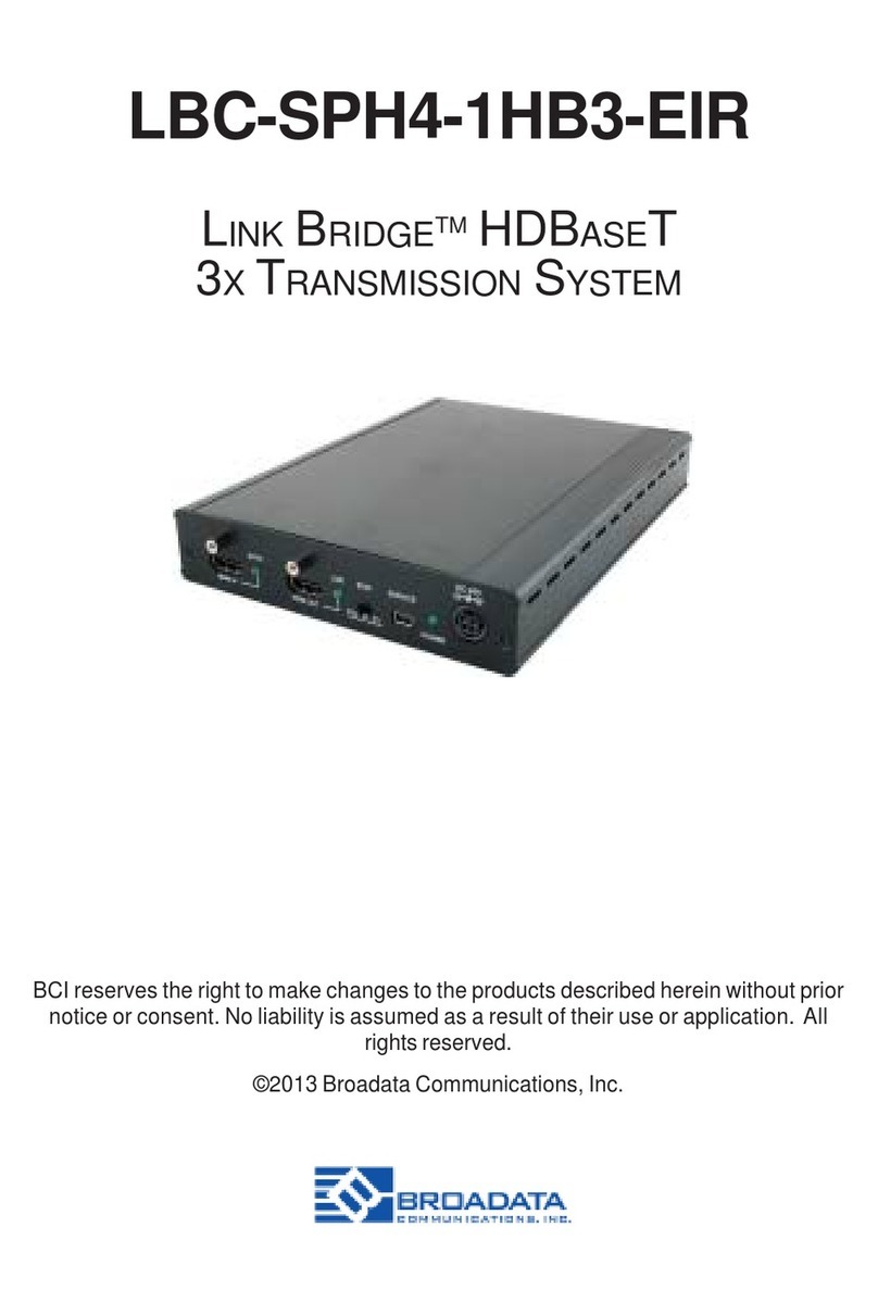
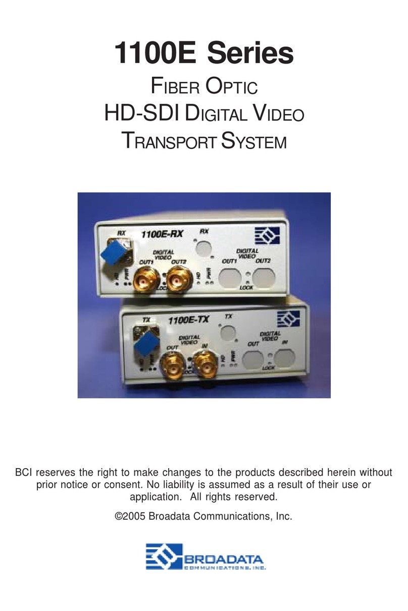
Broadata 300E Series User manual

300E Series
MULTIPLE CHANNEL DIGITAL FIBER OPTIC
VIDEO/AUDIO/DATA
TRANSPORT SYSTEM
BCI reserves the right to make changes to the products described herein without
prior notice or consent. No liability is assumed as a result of their use or
application. All rights reserved.
©2006 Broadata Communications, Inc.

BCI300EUser’sManual
Multiple Channel Video/Audio/Data Transmission System
SAFETY INSTRUCTIONS AND
COMPLIANCE DECLARATIONS
PLEASEOBSERVETHEFOLLOWINGSAFETY
PRECAUTIONSASOURPRODUCTSCONTAIN
CLASS I LASER PRODUCTS
WARNING
Do not disconnect the fiber optic connector while the unit is powered
up. Exposure to laser radiation is possible when the laser fiber optic
connector is disconnected while the unit is powered up.
Although the fiber optic connectors in this product emit only Class 1
energythatisbelowthelevelsconsidered to be hazardous, one should
neverstaredirectlyintoafiberopticconnectororanunconnectedfiber
end unless one can be certain that no exposure to laser energy could
occur.
CAUTION
This manual is intended for use by trained service personnel. The use
of controls, making adjustments, or performing operations other than
those specified may result in hazardous radiation exposure.
Thefollowinglabelorequivalentislocatedonthesurfaceoflaserproducts.
Thislabelindicatesthat the product is classified as a CLASS 1 LASER
PRODUCT.
SURGEPROTECTION DEVICERECOMMENDED
This product contains sensitive electrical components that may be
damaged by electrical spikes, surges, electric shock, lightning strikes,
etc. Use of surge protection systems is highly recommended in order
to protect and extend the life of your equipment.
CLASS 1 LASER PRODUCT

BCI300EUser’sManual
Multiple Channel Video/Audio/Data Transmission System
Broadata Technical Support, (800) 214-0222
4
TABLE OF CONTENTS
1.0 PRODUCT DESCRIPTION .............................................5
2.0 SETUP..............................................................................7
2.1 MOUNTING......................................................................8
2.2 CABLING AND CONNECTORS .....................................8
2.2.1 ELECTRICAL CABLE CONNECTION .........................8
2.2.2 OPTICAL FIBER CONNECTION.................................8
2.2.1.1 AUDIO CONNECTION.............................................10
2.2.1.2 VIDEO CONNECTION.............................................11
2.2.1.3 SERIAL DATA INTERFACE......................................12
2.3 AC POWER CONNECTION ..........................................15
3.0 OPERATION...................................................................16
4.0 MAINTENANCE AND TROUBLESHOOTING..............16
4.1 MAINTENANCE .............................................................16
4.2 TROUBLESHOOTING ..................................................17
5.0 SPECIFICATIONS..........................................................19
6.0 SERVICE PROCEDURE ...............................................21
6.1 REPLACEMENT POLICY .............................................21
6.2 RETURN AND REPAIR SERVICE.................................21
7.0 LIMITED WARRANTY....................................................22

BCI300EUser’sManual
Multiple Channel Video/Audio/Data Transmission System
1.0 PRODUCT DESCRIPTION
The310E/320Esystemsprovidesimultaneous transmission ofmultiple
channelsof digitizedstereoaudio,video and/ordataoveroneor onepair
of fiber. The standard 310E system transmits these video/audio/data
channelsinonedirection.The320Esystemtransmitsandreceivesthese
video/audio/datachannelsinbothdirections. The standard 310E/320E
system comes with 4- and 8-channel versions with each channel
containingone(1)NTSC/PAL/SECAMvideo,two (2)audios,and one(1)
serial data (RS-232/RS-422). Versions up to 16-channel video/audio/
dataarealsoavailableforunidirectionallinks.Inaddition,the310E/320E
has an option for S-video, and up to 8-channels of S-video can be
accommodated. The 310E/320E system is also capable of adding/
droppingvideo/audio/datachannelsinaringorbusnetworkconfiguration.
Please consult us for your custom design.
The 310E/320E features a digital fiber optic transmission technology,
capableofprovidingsharpervideoandcrispaudio,littleornomaintenance,
highfunctionalityreliability,andlowoperating cost. The qualityofvideo,
audioanddatatransmission in BCI'sdigitaldesigns ismuchsuperior to
theanalogtransmission(basedonamplitudeor frequency modulation)
designsusedby othermanufacturers. Nouser adjustmentsarerequired
inthe310E/320Esystem,enablingquicksetupandtrouble-freeoperation.
The310E/320Ecomesinarugged,standalone,andcompactunit.Panel
connectorsareprovidedforvideo(BNC),audio(terminalblock),anddata
(terminal block), and fiber connection (FC-type for singlemode fiber or
ST-typeformultimodefiber). Theyarealsoeasilymonitored byseparate
LED indicators for power, optical link, and channel activity.
Due to its digital transmission design, the 310E/320E is capable of
addressingavarietyofnon-standardconfigurations. Figure1-1shows
thefrontandrearpanelsofthe300ESeries.

BCI300EUser’sManual
Multiple Channel Video/Audio/Data Transmission System
Broadata Technical Support, (800) 214-0222
6
Figure 1-1
300E Front/Rear Panels
PWR
1 2 34
300E
RX
VIDEO
+_
_+_
_+_
_+_
_
12
34
56
78
6
5
7
8
2
1
3
4
AUDIO
PWR
1234
300E
TX
VIDEO
+_
_+_
_+_
_+_
_
12
34
56
78
6
5
7
8
2
1
3
4
AUDIO
12VDC

BCI300EUser’sManual
Multiple Channel Video/Audio/Data Transmission System
2.0 SETUP
TheBCI300ESeries units are usedinpairs. Inaunidirectional system,
one 310E transmitter is located at the near-end and connected to a
310E receiver located at the far-end, through a single fiber. In a
bi-directionalsystem,one300Etransceiverunitislocatedatthenear-end
andconnectedthroughtwoopticalfibers toanidentical 300Etransceiver
locatedatthe far-endofthelink. Each unitprovidesa separateelectrical
interface connector for the various audio, video and data signals.
Connections are one to one between the two units. Figure 2-1 depicts
two typical installations.
Figure 2-1
310E/320E Setup

BCI300EUser’sManual
Multiple Channel Video/Audio/Data Transmission System
Broadata Technical Support, (800) 214-0222
8
2.1 Mounting
Beforeinstallingtheunitsintoyourhousing,makesurethereis
enoughspacetopulland connect boththeelectricalandoptical
cables without stressing them beyond the manufacturer’s
limitations (also known as the bend radius minimum). Rack
Mountkitsareavailablethroughspecialorder.
2.2 Cabling and Connectors
In order to setup the BCI 300E properly, make sure to observe
thefollowinginstructions wheninstallingtheproper cables. The
300Erequirestwopartstothe cabling setup: the electrical and
the optical. For the optical part, observe the following
procedures,astherearevarious types of opticalconnectorsas
illustratedonthefollowingpage.
2.2.1 Electrical Cable Connection
On the electrical side, it is required that the following steps be
observed when connecting the various audio, video and data
terminal devices, as they all require special attention, and are
the only available electrical connections. They are described
in the following steps.
2.2.2 Optical Fiber Connection
Most cable manufacturers identify individual fibers in the fiber
cable. Selectanappropriateterminatedfiber. Each unit’soptical
portsin the system are specified for use with Multimode (62.5/
125 micron) fiber, or Singlemode (9/125 micron) fiber. Follow
the ensuing instructions for installing and connecting the fiber
optic links:
1. Ensure the power is off before proceeding with the fiber
optic cable installation.

BCI300EUser’sManual
Multiple Channel Video/Audio/Data Transmission System
2. Priortoconnectingthe fiberopticcables,remove and save
the dust caps from the optical port of both the 300E units
andtheuser’sdevice. Cleanthefiber optic connector and
use a lint-free cloth dampened with alcohol to thoroughly
wipethe side and end of the ferrule.
3. Cross-connect the fibers from one unit to the other,
connectingthe near end 300E unit’s optical TX port to the
far end 300E unit’s optical RX port, as illustrated in
Figure 2-2. Observe the type of connector you have and
connecttheopticalconnectorbyfollowingtheinstructions
andguidelinesfromthelegendprovidedinTable 1.
Figure 2-2
Fiber Optic Connection
PWR
1 2 34
300E
RX
VIDEO
+_
_+_
_+_
_+_
_
12
34
56
78
6
5
7
8
2
1
3
4
AUDIO
PWR
1234
300E
TX
VIDEO
+_
_+_
_+_
_+_
_
12
34
56
78
6
5
7
8
2
1
3
4
AUDIO

BCI300EUser’sManual
Multiple Channel Video/Audio/Data Transmission System
Broadata Technical Support, (800) 214-0222
10
Table 1
Fiber Optic Connector Legend
2.2.1.1 Audio Connection
Performthefollowingsteps to insureaproperaudio connection
(SeeFigure2-3):
Figure 2-3
AudioConnection
1. Audio connections are made possible by the provided
terminalblocks(SeeFigure2-4). Use 22-18 standard wire
(22-18-AWG) to connect between the user’s audio
equipment and the 300E unit. Use a flat head screwdriver
to tighten the terminal screws. Follow the proceeding
instructions to install the audio connections.
rotcennoC noitartsullI noitpircseD
TS
tresnidna*toobdeiler-niartsehtybrotcennocehtdloH litnutoobehtetatoR.tropehtotnielurrefrot
cennoceht ehthsuP.gnilpuocehtfotolsehtnisegagne"yek"eht denrutebnactilitnudrawrofgnisuohrotcennoc .trope
htothctalotesiwkcolc
CF
tresnidna*toobdeiler-niartsehtybrotcennocehtdloH litnutoobehtetatoR.tropehtotnie
lurrefrotcennoceht ehthsuP.gnilpuocehtfotolsehtnisegagne"yek"eht tilitnuesiwkcolcwercsdnadrawrofgnisuoh
rotcennoc .thgitsi
*
*
PWR
1234
300E
TX
VIDEO
+_
_+_
_+_
_+_
_
12
34
56
78
6
5
7
8
2
1
3
4
AUDIO

BCI300EUser’sManual
Multiple Channel Video/Audio/Data Transmission System
2. At the near end (the transmitter unit), connect the user’s
audio sources to the 300E unit’s audio input ports.
3. At the far end (the receiver unit), connect the user’s audio
receivers to the corresponding audio output ports on the
300Ereceiverunit.
Figure 2-4
2 x 10 Position Terminal Block
For balanced audio signals,
Connectthe(+), (-)and(G)of the300E’sterminalblock to
thecorrespondingterminaluser’s equipment.
For unbalanced audio signals,
Connect the (-) and (G) of the 300E’s terminal block as
well as the (+) terminal to the (+) terminal of the user’s
equipment and (-) or (G) of the 300E unit to the ground
terminaloftheuser’sequipment.
2.2.1.2 Video Connection
The 300E video connectors accept 75 ohm coaxial cable
terminated by a BNC connector (i.e., RG 59U with a BNC
connector). Usethefollowingstepstoconnectthevideocables.
1. At the near end, on the transmitter unit, connect the user’s
videosourcestothevideo-inputportsofthe300Eunit. Also,
connecttheuser’svideo receivers tothevideooutput ports
ofthe300E-receiverunit. (SeeFigure 2-5).
2. Repeatthisprocedureforthefar end unit.
XXXXX
XXXXX
(+) (-) (+) (-)
34
12

BCI300EUser’sManual
Multiple Channel Video/Audio/Data Transmission System
Broadata Technical Support, (800) 214-0222
12
Figure 2-5
Video Connection
Note: Make sure the video channels match on both ends.
2.2.1.3 Serial Data Interface (320E bi-directional
series only)
Each320Eunit isequippedwitheither anRS-232or anRS-422
interface,whichispresetatthefactory. Follow the proceeding
instructionsdepending on what data type you have installed.
RS 232 unbalanced data
The 320E units transport unbalanced data signals with
handshaking control, and are compatible with Full Duplex
RS-232(C,D,andE)type devices. Use the following stepsfor
connectingdatatransmissionequipment:
1. Connectyourserial datacabletothe user’sRS-232device.
(SeeFigure2-6).
2. Connecttheotherendofthiscabletothefront panelRS-232
female DB9 connector of the 320E TX unit.
3. Repeat step 1 and 2 for the 320E RX unit.
PWR
1234
300E
TX
VIDEO
+_
_+_
_+_
_+_
_
12
34
56
78
6
5
7
8
2
1
3
4
AUDIO

BCI300EUser’sManual
Multiple Channel Video/Audio/Data Transmission System
Figure 2-6
Data Connection
Figure2-7shows pinconnectionsbetweenthe 320ESeriesunit
(asaDCEunit)forChannel1.
Figure 2-7
Pin Connections Between the 320E Series Unit and the
User’s RS-232 Device
PWR
1 2 34
300E
TX
VIDEO
+_
_+_
_+_
_+_
_
12
34
56
78
6
5
7
8
2
1
3
4
AUDIO
5
6
7
8
+_
_+_
_
1
2
3
4
TX
RX
LINK
PWR
D A T A P O R T S
+_
_+_
_+_
_+_
_+_
_+_
_
+_
_+_
_
XXXXX
XXXXX
In
GNDOut
2
1

BCI300EUser’sManual
Multiple Channel Video/Audio/Data Transmission System
Broadata Technical Support, (800) 214-0222
14
RS-422 differential serial data
The320Eunitstransportdifferentialdatasignalswithcompatible
Full Duplex RS-422 type devices. Note that RS-422 does not
support handshaking control signals. Use the following steps
whenconnectingdatatransmissionequipment:
1. Connectyourserial datacabletothe user’sRS-422device.
(SeeFigure2-6).
2. Repeat step 1 for the 320E RX unit.
Figure 2-8 shows pin connections between the 320E Series
unit (as a DCE unit).
Figure 2-8
Pin Connections Between 320E Series Unit and User’s
RS-422 Device
+_
_+_
_
XXXXX
XXXXX
2
1
320E
Out (+) Out (-) In (+) In (-)
RS-422E

BCI300EUser’sManual
Multiple Channel Video/Audio/Data Transmission System
2.3 AC Power Connection
Congratulations! You arenowreadytopoweruptheBCI300Eandset
up your network connection. In order to make sure that you have a
properinstallation,pleaseobservethe following:
1. YourAC jack has power.
2. Yourelectricalsystemhaspropergrounding(thisensuresthat
yourpowersupplydoesnotsuffer from voltage variations).
3. Power Surge Protection. This is optional, but highly
recommended. A UPS system provides voltage regularity as
well as prevents spikes from occurring, thus protecting your
300Efromsensitivevoltageconditions.
The 300E derives power from an internal power supply. This power
supplyis a 110-240 VAC, 50-60 Hz, at 2.2A. This power supplycomes
standardforthe300Eunlessotherwisespecified.
To provide power to the 300E, simply connect the power cord, already
providedwiththeunits,andconnectitto the wall jack. (Youwillfindone
power cord per unit). Once the power cord has been connected to the
wall jack, connect the other end of the cord to the unit and turn the
switch on (I).
Ifyouhaveanyproblemsorconcerns,regardingtheinstallation,make
sure that you have taken the proper steps to ensure a proper power
connection. Otherwise, feel free to contact us for any questions you
mayhave.

BCI300EUser’sManual
Multiple Channel Video/Audio/Data Transmission System
Broadata Technical Support, (800) 214-0222
16
3.0 OPERATION
After the installation procedure is completed, the units are ready for
operation. To operate the BCI 300E units, simply apply power as
indicated in the previous step. Note that the front panel link status
indicator, shown in Table 2, will be activated.
4.0 MAINTENANCE AND TROUBLESHOOTING
4.1 Maintenance
Thereisnooperatormaintenanceotherthen keeping the units
clean. However, observe the following light indicatorstomake
sure that the unit is working properly:
Table 2
Status Indicators
rewoPXT ehttahtsetacidnirettimsnartehtnoDELDERsihT .derewopylreporpsitinu
kniL/rewoPXR
setacidnireviecerehtnosDELNEERGroDERehT DELehtnehW.derewopylreporpsitinuehttaht tinureviece
reht,rolocNEERGotDERmorfsegnahc ylreporpgnitarepodnadeknilyllacitposi
OEDIV XR/XTnoitceteD oedivehtfohcaetahtsetacidniDELNEERGehT .evitcaerasrotcennoc)XR(tuptuoro)XT(tupni
pilCOEDIV XTmralA
ehtfohcaetalevellangisehtsetacidniDELDERehT dnoyebdegnar-revoeralangis)XT(tupnioediv .p
pV2.1

BCI300EUser’sManual
Multiple Channel Video/Audio/Data Transmission System
4.2 Troubleshooting
If the BCI 300E units do not operate properly after installation,
check for possible cable breaks, loose connections, and
incorrect cable connections. If a problem exists on the fiber
link,pleasecheckyourfiber connectors for improperlycleaned
fiber cables and connectors. If problems persist that may be
fiber related, contact BCI at 1-800-214-0222 for further
assistance.
For electrical problems, perform the following troubleshooting
procedures:
1. If the POWER indicator is OFF, check for the following:
a. The line cord is plugged into the unit and your outlet
haspower.
b. The 300E unit is switched on.
c. Check for blown fuses (located in the rear panel-entry
module).
2. If the POWER indicator is ON, but the Optical Link
indicator is OFF, check for the following:
a. Makesuretheappropriate(Singlemode or Multimode)
fibersarebeingused.
b. Fiber and fiberconnectorsarenotbroken. Ensure that
the optical loss does not exceed the specified optical
power attenuation (see Section 5.0 Specifications for
theopticalpowerbudget).
c. For each unit, the transmit (TX) fiber is connected to
theotherunit’sreceiver(RX).

BCI300EUser’sManual
Multiple Channel Video/Audio/Data Transmission System
Broadata Technical Support, (800) 214-0222
18
3. If the POWER indicator and Optical Link indicator are
ON, but the audio/video channels are not operating,
then:
a. Checktosee thattheattacheduserequipment isturned
on.
b. Bothendsofthelinkareconnectedtothe corresponding
equipmentandtothesamecorrespondingchannelport.
c. Cable connections at both the video/audio channels
aresecurelyfastenedtoeachconnector. Turnthepower
off, then back on to reset the link.
d. Outputlevelsofthe user’svideoandaudiosources are
not above the allowed input levels of the 300E units
(see Section 5.0 Specifications).

BCI300EUser’sManual
Multiple Channel Video/Audio/Data Transmission System
5.0 SPECIFICATIONS
Video
VideoFormat NTSC,PAL,S-Video
ChannelCapacity 4, 8, or 16* (NTSC or PAL)
2, 4, or 8* (S-Video)
Bandwidth 8 MHz
ModulationResolution 10 Bits (12 Bits optional)
VideoLevel 1.2Vp-p @ 75 Ohms
DifferentialGain <1%
DifferentialPhase <0.7o
SNR(Weighted) >70dB
Connector BNC
Audio
ChannelCapacity 8, 16, or 32*
OperatingMode BalancedorUnbalanced
Input/OutputImpedance 600Ohms/600 Ohms
(Balanced)
Max.Input/OutputLevel +10 dBm (Balanced)
MagnitudeFreq.Response 20Hz to 24kHz
THD+N >85dB@1kHz(Balanced)
Connector TerminalBlock
Serial Data
ChannelCapacity 4, or 8
SignalFormat RS-232or RS-422
DataRate Upto128 kbps (RS-232)
Upto256kbps(RS-422)
Connector TerminalBlock
Physical
Dimension: (H x W x D)
StandaloneUnidirectionalVersions: 1.72" x 8.58" x 12.0"
StandaloneBi-directionalVersions: 1.72" x 17.03" x 12.0" (2/4 ch)
3.46" x 17.03" x 12.0" (8 ch)
Power(Unidirectional2/4/8TX/RX) 12VDC@ 25/25/50W

BCI300EUser’sManual
Multiple Channel Video/Audio/Data Transmission System
Broadata Technical Support, (800) 214-0222
20
Power(Bi-directional2/4/8TX/RX) 110-240VAC@60/60/120W
OperatingTemperature 0 to +50oC
Humidity 0 to 95% RH,
non-condensing
StatusIndicators Power, OpticalLink,
VideoActivity
Optical
FiberType MultimodeandSinglemode
NumberofFibers 2 or 1
Wavelength 850,1310and/or1550 nm
FiberOpticConnector ST(forMultimode)
FC(forSinglemode)
*The 16-ch video/32-ch audio option comes with unidirectional links only (i.e., bi-
directional links are not available)
TT
TT
Typical Pypical P
ypical Pypical P
ypical Power Budget and Tower Budget and T
ower Budget and Tower Budget and T
ower Budget and Transmission Distanceransmission Distance
ransmission Distanceransmission Distance
ransmission Distance
(1) These are typical values for the 310E/320E Series. The actual values may vary.
(2) These are typical distance coverage figures. The maximum distance coverage may be
greater than these typical numbers, depending on fiber type, fiber bandwidth, connector
splicing losses, chromatic dispersion, environmental factors, etc.
Multimode Fiber 8 0.5 0.3
Singlemode Fiber 14 25 16
Multimode Long Distance 14 2 1.25
Singlemode Long Distance 20 60 37
PowerPower
PowerPower
Power
Budget (1)Budget (1)
Budget (1)
TT
TT
Typicalypical
ypicalypical
ypical
DistanceDistance
DistanceDistance
Distance
KM (2)KM (2)
KM (2)KM (2)
KM (2)
TT
TT
Typicalypical
ypicalypical
ypical
DistanceDistance
DistanceDistance
Distance
Miles (2)Miles (2)
Miles (2)Miles (2)
Miles (2)
ApplicationApplication
Application

BCI300EUser’sManual
Multiple Channel Video/Audio/Data Transmission System
6.0 SERVICE PROCEDURE
6.1 Replacement Policy
Standard products found defective on arrival (DOA) will be
replaced,basedonavailability,within24to48hours anywhere
in the U.S. Please call Customer Service at 800-214-0222 for
information.
6.2 Return/Repair Service
The310ESystemcontainsno user serviceablecomponents.If
youhavea problemwithyourunit, pleasecontactthe Customer
Service Department. To facilitate our return/repair processing
please contact Broadata Communications, Inc. to obtain a
Return Material Authorization (RMA). Please include the
followinginformation:
• Productmodelnumber
• SerialNumber
• Completedescriptionofproblem
• Hardwareinstallationdescription
BroadataCommunications,Inc.
2545 West 237th Street, Suite K
Torrance,CA 90505
1-800-214-0222
(310)530-1416
(310)530-5958(Facsimile)
e-mail:[email protected]
Website:www.broadatacom.com
Table of contents
Other Broadata Network Hardware manuals
Popular Network Hardware manuals by other brands

ZyXEL Communications
ZyXEL Communications IES-1248-51V Support notes

Patton electronics
Patton electronics Model 2711 user manual

Avaya
Avaya INDeX CSLC installation manual

Fortinet
Fortinet FortiGate FortiGate-ASM-FB4 Technical note

Siemens
Siemens FastConnect RJ45 Plug 90 Assembly instructions

Obihai
Obihai OBi100 quick start guide

Fortress Technologies
Fortress Technologies ecure Wireless Access Bridge user guide

Riverbed
Riverbed SteelHead 570-SD installation guide

PairGain
PairGain HLU-319 manual

MicroNova
MicroNova O047 Technical installation manual

ANEP
ANEP P4GU VoLTE Technical data sheet

Huawei
Huawei CR52K-2xPOS/STM64 Specifications