Broadcom ASG-S200 User manual

24 Aug 2021
Broadcom, the pulse logo, Connecting everything, Avago Technologies, Avago, the A logo, Symantec, the Symantec logo, the Checkmark logo, Blue Coat, and the Blue Coat
logo are among the trademarks of Broadcom and/or its affiliates in the United States, certain other countries, and/or the EU. Copyright © 2021 Broadcom. All Rights Reserved.
The term “Broadcom” refers to Broadcom Inc. and/or its subsidiaries. For more information, please visit www.broadcom.com.
Figure 1: ASG-S200, ASG-S400, ASG-S500 Deployments
Advanced Secure Gateway Quick Start Guide
ASG-S200, ASG-S400, ASG-S500 Appliances

ASG-S200, ASG-S400, ASG-S500
2
Advanced Secure Gateway
Quick Start Guide
1 — Unpack the Appliance
Unpack the shipping package for the appliance and verify it
includes the following:
2 — Connect Cables
It is recommended that you plug in cables, verify LEDs, and
configure and license the appliance before mounting it in an
equipment rack. Make sure the appliance is on a flat, level
surface when performing the initial configuration. If you would
rather mount the appliance before performing configuration
tasks, skip to Mount the Appliance.
The following procedure describes a typical
in-line
deploy-
ment for
ASG-
S200,
ASG-
S400, and
ASG-
S500 appliances
(as shown in Figure 1). For information on other deployments,
see the
Advanced Secure Gateway
software documentation,
available at:
techdocs.broadcom.com
NOTE: Network cables are not included with the appliance.
Make sure to use only straight-through Ethernet cables.
Category 5E cables or better are recommended for
1000Base-T operation. Category 6A cables are
recommended for 10GBase-T operation.
To deploy the appliance and connect cables:
1. Disconnect the Ethernet cable (if there is one) between
the LAN switch and WAN router.
2. Connect the appliance to the LAN switch:
For ASG-S200 and ASG-S400 appliances, connect an
Ethernet cable to the appliance’s LAN 2:0 port and con-
nect the other end of the cable to the LAN switch.
For ASG-S500 appliances, connect an Ethernet cable
to the appliance’s LAN 1:0 port and connect the other
end of the cable to the LAN switch.
The appliance auto-negotiates 10/100/1000 Base-T
speed and duplex settings.
3. Connect the appliance to the WAN router:
For ASG-S200 and ASG-S400 appliances, connect an
Ethernet cable to the appliance’s LAN 2:1 port and con-
nect the other end of the cable to the WAN router.
For ASG-S500 appliances, connect an Ethernet cable
to the appliance’s LAN 1:1 port and connect the other
end of the cable to the WAN router.
4. Connect an Ethernet cable to the appliance’s MGMT 0:0
port and connect the other end of the cable to the man-
agement network switch.
5. Connect the included null-modem cable to the appli-
ance’s DB9 Serial port and connect the other end of the
cable to a serial terminal or workstation with terminal
emulation software. The serial connection is used to per-
form the appliance’s initial configuration.
6. For ASG-S500 appliances, attach the lug-equipped end
of the included grounding wire (10 AWG) to both ground-
ing studs on the appliance, securing it with the star
washers and M5 nuts. Attach the other end of the
grounding wire to a proper earth-ground.
7. Connect the appliance to a power source:
For ASG-S200 appliances, connect the included power
cord to the appliance’s power inlet and connect the
other end of the power cord to a power source.
For ASG-S400 and ASG-S500 appliances, connect the
included power cords to the appliance’s power inlets
and connect the other ends of the power cords to a
power source.
Appliance ASG-S200 ASG-S400 ASG-S500
AC power cords
(number included)
122
Null-modem serial cable √ √
Grounding hardware √
2- and 4-post slide-rail kit optional √ √
2-post fixed rail √
Accessing Appliance
Documentation
√√√
Software License Agreement
√√√
Hardware Warranty
Information
√√√

ASG-S200, ASG-S400, ASG-S500
3
Advanced Secure Gateway
Quick Start Guide
3 — Power On the Appliance and
Verify LEDs
To verify the appliance is operational:
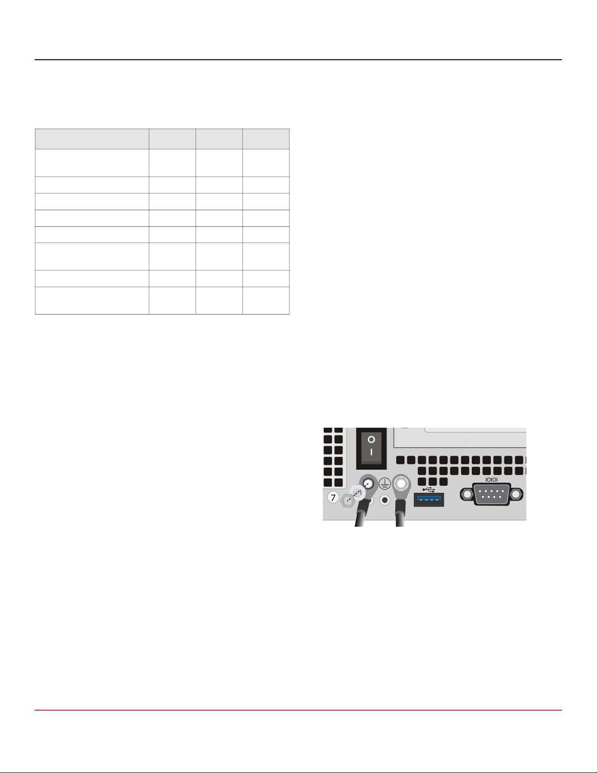
1. Confirm the appliance’s power cords are securely
connected to a power source.
2. If the appliance does not automatically power on, press
the rear soft power switch.
NOTE: The state of the appliance’s soft power switch (on
or off) is retained when power is removed. This may ne-
cessitate pressing the power switch when reapplying
power to the appliance.
3. As the appliance boots, verify the following:
The power LED turns amber.
Near the end of the boot cycle, the Power LED alter-
nates between amber and green, indicating an uncon-
figured state.
After the boot cycle has completed, the LCD panel dis-
plays information about the appliance, such as model,
serial number, and IP address, which can be scrolled
through with the Right and Left Arrows.
Following the initial configuration and licensing, the
Power LED turns green.
During operation, the front-panel status LEDs indicate the
following states:
4 — Perform the Initial Configuration
NOTE: To initialize the appliance, you need the following:
appliance IP address, primary DNS server IP address;
default gateway IP address; subnet mask; console
password for advanced CLI commands; admin password for
access to the appliance.
To perform the initial configuration for the appliance:
1. Confirm the appliance’s DB9 Serial port is connected to
a serial terminal or workstation with terminal emulation
software.
2. Open a terminal emulation program, such as Microsoft
HyperTerminal®, PuTTY, Tera Term, or ProComm™,
and configure it to use the following settings:
3. Power on the appliance (if it is not already powered on)
and, when prompted, press Enter three times.
4. Choose Manual Setup to launch the Initial Configura-
tion Wizard.
5. When prompted, enter network configuration parameters.
5 — License the Appliance
The Advanced Secure Gateway appliance requires a base li-
cense for the primary ProxySG and Content Analysis compo-
nents. Add-on licenses provide access to optional components
for file inspection and specialized Proxy features.
To license the appliance:
1. Open a browser and enter the appliance’s IP address
and port number. For example, an IP address of
192.168.2.42 with a port number of 8082 (the default),
would be: https://192.168.2.42:8082.
2. When prompted, enter the admin Username and Pass-
word specified during the initial configuration, then click
Login. The Management Console window opens.
3. Activate the base license:
In the Management Console window, navigate to the
Proxy > Maintenance > Licensing > Install tab.
Click Retrieve. The appliance downloads the base
license from the licensing server and installs it.
LED Color Description
Power
Status
Off Powered off or no power present
Amber Booting
Amber/green
alternating
Not yet initialized
Green Powered on and configured
System
Status
Off Powered off or no power present
Green Normal
Amber System fault or not yet licensed
Amber blinking Critical fault
Baud rate: 9600 bps Data bits: 8
Parity: none Stop bits: 1
Flow control: none

ASG-S200, ASG-S400, ASG-S500
4
Advanced Secure Gateway
Quick Start Guide
4. Activate any add-on licenses that were purchased:
Go to support.broadcom.com/security and click My
Entitlements. When prompted, enter the admin
Username and Password.
Search for the appliance you want to license by enter-
ing its Serial Number, Site ID, or Email.
When the appliance appears, click the License
Download icon.
Repeat the previous steps to install any additional add-
on licenses.
5. If any add-on licenses were installed, download and in-
stall the updated base license:
In the Management Console window, navigate to the
Proxy > Maintenance > Licensing > Install tab.
Click Retrieve. The appliance downloads the updated
base license from the licensing server and installs it.
6. Activate and view the installed licenses and services:
In the Management Console window, navigate to the
Content Analysis > System > Licensing tab.
Each licensable service shows the following:
–Status: The availability of a service component and
its expiration date.
–Active: The activation status of the component.
To activate a service component, click its checkbox.
Click Save Changes.
6 — Perform a Graceful Shutdown
Before mounting the appliance, log in to CLI and perform a
graceful shutdown of the appliance.
To perform a graceful shutdown:
1. Open a terminal emulation program and log in to the
appliance.
NOTE: Confirm the appliance’s DB9 Serial port is con-
nected to a serial terminal or workstation and that the ter-
minal emulation software is configured as in Perform the
Initial Configuration.
2. When prompted with the Serial Console welcome
screen, to access CLI, press: 1
3. To access privileged commands, enter: enable
4. When prompted, enter the enable Password specified
during the initial configuration.
5. Enter: shutdown
WARNING!
Do not power off the appliance with the soft pow-
er switch or by removing the power cables! Abruptly removing
power can result in irreparable data loss. Always use the
shutdown command from CLI to power off the appliance.
7 — Mount the Appliance
The slide-rail kit included with
ASG-S400
and
ASG-S500
ap-
pliances (available as an option for
ASG-S200
appliances)
allows the appliance to be mounted in a 4- or 2-post equip-
ment rack. The slide-rail kit includes the following parts:
NOTE: Installation of the slide rails requires an M4 nut driver
or adjustable wrench and a #2 Phillips head screwdriver. If
you are working alone, a mechanical lift is also required.
NOTE: The following procedure documents installation for 4-
post equipment racks (as shown in Figure 2). For 2-post instal-
lation, see the S-Series WebGuide, available at:
techdocs.broadcom.com/sseries
Item
(2) Front brackets
(2) Inner rails
(2) Rear brackets
(2) Center brackets
(2) Rack ears
(8) M6x13 screws
(8) M6 cage nuts
(10) M4x4L screws
(4) M3L4 screws
ASG-S200 (Optional) and ASG-S400 Rail Kit
Item
(2) Front brackets
(2) Inner rails
(2) Rear brackets
(4) Middle brackets
(8) M6x13 screws
(8) M6 cage nuts
(10) M4x5L screws
(4) M4x4L screws
ASG-S500 Rail Kit

ASG-S200, ASG-S400, ASG-S500
5
Advanced Secure Gateway
Quick Start Guide
Rack Warnings and Precautions
CAUTION! Before mounting the appliance:
Power off the appliance (see Perform a Graceful
Shutdown) and disconnect all cables.
Verify that the weight of the system does not exceed the
rack’s fully populated weight limit. For more information,
refer to the manufacturer’s instructions included with
the rack.
For weight stability, load the rack from the bottom up.
Read the “Rack Mount Warnings” section of the Safety
and Compliance Guide.
Take adequate safety and grounding measures to avoid
creating an electrical shock hazard and to prevent
bodily injury.
The appliance is heavy. A two-person lift or mechanical
aid is recommended to lift the appliance from the carton
and install it in the rack.
Do not place objects on the appliance or use it as a
work surface. Its mounting hardware does not support
additional weight.
Install the Appliance into the Rack
To install the appliance into a 4-post equipment rack:
1. Disassemble the two slide-rail assemblies. Extend the
inner rails while pressing the center release tabs, then
fully remove them (a).
2. Attach the two inner rails to the chassis sides, aligning
the rails with the mounting posts on the chassis, then
slide the rails forward (ASG-S200, ASG-S400) or rear-
ward (ASG-S500) until they snap into place. Secure
each rail with one (ASG-S200, ASG-S400) or two
(ASG-S500) M4x4L screws (b).
3. For ASG-S200 and ASG-S400 appliances, attach the
two rack ears to the chassis, aligning them with the
raised screw holes and orienting them with the captive
screw heads toward the front of the appliance. Secure
each rack ear with two M3L4 screws.
4. Install the two outer rails into the 4-post equipment rack (
c
):
Secure the rear brackets to the front brackets with six
M4x4L (ASG-S200, ASG-S400) or M4x5L (ASG-S500)
screws, three per side, placed equidistantly. Do not yet
fully tighten the side-mounting screws.
Figure 2: ASG-S500 Slide-Rail Installation

ASG-S200, ASG-S400, ASG-S500
6
Advanced Secure Gateway
Quick Start Guide
Broadcom reserves the right to make changes without further notice to any products or data herein to improve reliability, function, or design. Information furnished by Broadcom is believed to be accurate and reliable. However, Broadcom does not assume
any liability arising out of the application or use of this information, nor the application or use of any product or circuit described herein, neither does it convey any license under its patent rights nor the rights of others. (2021.08.24, 13:07:44)
Attach the two outer rails to the rack, extending the rails
as necessary to fit the rack. Secure the front and rear
brackets with two M6 rack screws each. Do not yet fully
tighten the rack screws.
Fully tighten the side-mounting screws, three per side,
securing the rear brackets to the front brackets.
Inspect the outer rails, making sure they are installed at
the same level in the rack and free of defects, damage,
and debris. Verify the rails extend and retract smoothly
and stop at the slide-stop.
5. Install the chassis into the 4-post equipment rack (d):
Align the inner rails attached to the appliance with the
outer rails in the rack and slide the appliance half-way
into the rack.
Fully tighten the M6 rack screws securing the outer rails
to the rack.
Press the release tabs on the inner rails and gently
slide the appliance all the way into the rack.
Tighten the captive thumbscrews on the appliance’s rack
ears to prevent the appliance from sliding out of the rack.
6. Reconnect the cables as documented in Connect Cables
and verify the appliance is functioning as in Power On the
Appliance and Verify LEDs.
See below for support and additional documentation.
Symantec Technical Support
For Symantec technical support, case management,
licenses, and product downloads, go to:
support.broadcom.com/security
Advanced Secure Gateway Software Documentation
Go to techdocs.broadcom.com and type “asg” in the
search field, then click Advanced Secure Gateway.
Appliance Documentation
S Series WebGuide (Maintenance and Upgrades)
techdocs.broadcom.com/sseries
S200 Series Safety and Compliance Guide
techdocs.broadcom.com/s200
S400 Series Safety and Compliance Guide
techdocs.broadcom.com/s400
S500 Series Safety and Compliance Guide
techdocs.broadcom.com/s500
This manual suits for next models
2
Table of contents
Other Broadcom Gateway manuals