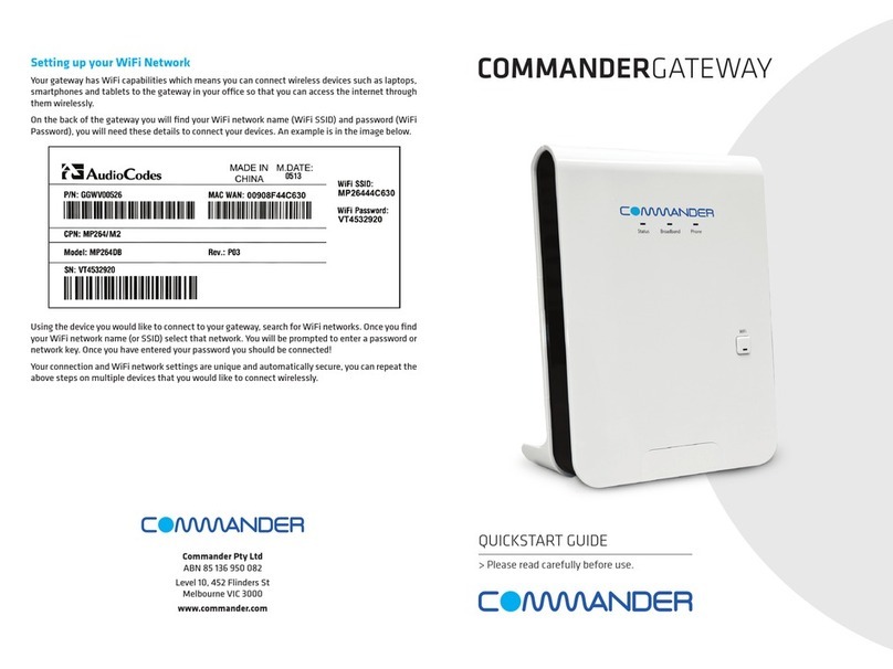
Commander Pulse User manual

Pulse
Owner’s Manual
Everything you need to know
about your Pulse equipment

1
Commander Pulse
Owner’s Manual
Rev 1
April 06

2
Table of Contents
1Introduction............................................................................5
Important Safety instructions ................................................5
Basic Requirements..............................................................7
Using this Document.............................................................7
2Getting to know your Commander Pulse .............................9
Parts Check...........................................................................9
Front Panel..........................................................................10
3Connecting Your Commander Pulse .................................11
Step 1: Siting your Commander Pulse Unit .......................11
Step 2: Connect your telephones and PSTN
Line(s) ..............................................................................12
Fit the Cable Cover over the phone
connections......................................................................13
Step 3 Internet Access Connections..................................13
Connecting to an external modem .....................................14
Step 4 Connect the Power .................................................14
Step 5 DECT Phones .........................................................15
Step 6 Connecting to the Internet.......................................16
Cabling Keystations & Standard telephones .....................17
Wall Mounting the Commander Pulse ...............................18
Keystation connections (underside of phone)....................19
Attaching the keystation desk plinth...................................20
Wall-mounting a keystation ................................................20
Door station.........................................................................22
Power Fail Telephone.........................................................22
4Basic programming using the Management
Application .......................................................................23
Basic PABX Settings ..........................................................24
Basic Router Configuration for an ADSL
connection .......................................................................30
Basic Router Configuration for a Cable Modem
connection .......................................................................31
Date & Time Settings..........................................................33
5Using Your Commander Pulse Phone System .................34
System Description.............................................................34
Introduction to your Commander Pulse Phones................34
System Keystation ..............................................................36
Using the DECT Handset ...................................................42
Keystation – Basic Call Features .......................................46

3
Using a Standard or DECT Handset..................................54
Additional Call Features......................................................58
Station Set-Up options........................................................64
Incoming Call Handling.......................................................66
Using Voicemail ..................................................................67
Remote Notification of Voice Messages ............................70
Programming Additional System Options..........................74
6Connecting to the Internet ..................................................76
ADSL Modem configuration ...............................................76
Types of Internet Access ....................................................76
Configuring a PPPoA ADSL connection ............................76
Configuring a PPPoE ADSL connection ............................78
Configuring a DHCP ADSL connection – RFC
1483 .................................................................................82
Changing the ADSL Modem Operating Mode...................85
Connecting to an External ADSL Modem,
Cable Modem, LAN, WAN or add a host to
the DMZ ...........................................................................86
Password ............................................................................90
DHCP Server ......................................................................92
Addressing ..........................................................................95
Changing the LAN IP address and subnet
mask ................................................................................95
7PABX Configuration using the web interface.....................97
Incoming Ringing ................................................................98
System Settings ..................................................................99
Station Settings .................................................................102
Line Settings .....................................................................108
Line Forwarding ................................................................109
Class of Service ................................................................110
Timers................................................................................112
LCR Programming............................................................113
CLI Routes ........................................................................115
Outgoing Restriction .........................................................116
8Advanced Router Settings................................................118
Wireless Setup / Security..................................................118
Firewall ..............................................................................131
Diagnostics........................................................................144
Firmware Update ..............................................................150
System Resets..................................................................153
AConfiguring Your Commander Pulse via the
Keystation ......................................................................155

4
To enter system programming .........................................155
System Setup Options......................................................155
Using Voicemail ................................................................166
Programming Additional System Options........................172
Miscellaneous system configuration options ...................173
To configure PSTN lines...................................................176
To set system timers.........................................................179
To reset your system ........................................................180
BDECT Handset Detailed Instructions ...............................181
CIP Addresses, Network Masks & Subnets .......................193
IP Addresses.....................................................................193
Subnet masks ...................................................................194
DGlossary ............................................................................195
EConfiguring your PCs........................................................202
Configuring Ethernet PCs.................................................202
FTroubleshooting ................................................................207
Cannot browse the Internet ..............................................207
Troubleshooting your Cordless Phone.............................212
Troubleshooting the PABX ...............................................213

5
1 Introduction
Congratulations on becoming the owner of the Commander
Pulse combined voice & data communications system. You will
now be able to access the Internet using your high-speed DSL
connection, share your phone connection between fixed &
cordless handsets
This User Guide will show you how to connect Commander
Pulse gateway, and how to customize its configuration to get
the most out of your new product.
Important Safety instructions
When using your telephone equipment, basic safety
precautions should always be followed to reduce the risk of fire,
electric shock, and injury to persons, including the following:
•Read and understand all instructions.
•Follow all warnings and instructions marked on the product.
•Unplug this product from the wall outlet before cleaning. Do
not use liquid cleaners or aerosol cleaners. Use a damp
cloth for cleaning.
•Do not use this product near water (for example, in a wet
basement).
•Do not place this product on an unstable cart, stand, or
table. The product can fall, causing serious damage to the
product.
•Slots and openings in the cabinet and the back or bottom
are provided for ventilation, to protect it from overheating;
these openings must not be blocked or covered. This prod-
uct should never be placed near or over a radiator or heat
register. This product should not be placed in a built-in
installation unless proper ventilation is provided.
•This product should be operated only from the type of
power source indicated in the manual. If you are not sure of
the type of power source to your building, consult your
dealer or local Power Company.
•The mains power socket outlet must be located near the
product and must be easily accessible to allow
plugging/unplugging.
•Do not allow anything to rest on the power cord. Do not
locate this product where persons walking on it will abuse
the cord.
•Do not use a station cord with this product’s AC power
cord. The AC outlet for this product should not be used for
any other electrical equipment.
•Never push objects of any kind into this product through
cabinet slots as they can touch dangerous voltage points or
short out parts that could result in a risk of fire or electric
shock. Never spill liquid of any kind on the product.

6
•To reduce the risk of electric shock, do not disassemble this
product, but take it to a qualified serviceman when some
service or repair work is required. Opening or removing
covers can expose you to dangerous voltages or other
risks. Incorrect re-assembly can cause electric shock when
the product is subsequently used.
•Unplug this product from the wall outlet and refer servicing
to qualified service personnel under the following
conditions:
- When the power supply cord or plug is damaged or
frayed.
- If liquid has been spilled into the product.
- If the product has been exposed to rain or water.
- If the product does not operate normally by
following the operating instructions.
•Adjust only those controls that are covered by the operating
instructions because improper adjustment of other controls
can result in damage and will often require extensive work
by a qualified technician to restore the product to normal
operation.
•If the product has been dropped or the cabinet has been
damaged.
•If the product exhibits a distinct change in performance.
•Avoid using a telephone (other than a cordless type) during
an electrical storm. There can be a remote risk of electric
shock from lightning.
•Do not use the telephone to report a gas leak in the vicinity
of the leak.

7
Basic Requirements
In order to use all the features of the Commander Pulse system,
you must have the following:
-ADSL service up and running on your telephone line
(or an equivalent broadband Internet access).
-Instructions from your ISP on what type of Internet
access you will be using, and the addresses needed
to set up access.
-One or more computers each containing an Ethernet
card (10Base-T/100Base-T network interface card
(NIC)).
-For system configuration using the supplied web-
based program: a web browser such as Internet
Explorer v4 or later, or Netscape v4 or later. Note
that version 4 of each browser is the minimum
version requirement – for optimum display quality,
use Internet Explorer v5, or Netscape v6.1.
Note
You do not need to use a hub or switch in order to connect more
than one Ethernet PC to your Commander Pulse. Instead, you
can connect up to four Ethernet PCs directly to your Commander
Pulse using the ports labeled on the rear panel.
Using this Document
Notational conventions
Acronyms are defined the first time they appear in the text and
also in the glossary.
The term LAN refers to a group of Ethernet-connected
computers at one site.
The term WLAN refers to a group of Wireless-connected
computers at one site.
Typographical conventions
Italic text is used for items you select from menus and drop-
down lists and the names of displayed web pages.
Bold text is used for text strings that you type when prompted by
the program, and to emphasize important points.
Special messages
This document uses the following icons to draw your attention to
specific instructions or explanations.
Note Provides clarifying or non-essential information on the current
topic.

8
Definition
Explains terms or acronyms that may be unfamiliar to many
readers. These terms are also included in the Glossary.
WARNING
Provides messages of high importance, including messages
relating to personal safety or system integrity.

9
2 Getting to know your Commander Pulse
Parts Check
In addition to this document on CD, your package should arrive
containing the following:
1 Commander Pulse Unit
1 Power Supply Commander
Pulse (PSU)
1 Blue (Ethernet WAN) cable
RJ-45
1 Documentation Pack 1 Cordless handset & charger
1 Yellow (Ethernet LAN)
cable RJ-45
1 Main distributor frame cover
(MDF)
1 Gray line cable
(RJ-11 to RJ11)
1 Violet ADSL cable
(RJ-11 to RJ-11)

10
Front Panel
The front panel contains a ‘Page’ button and lights called Light
Emitting Diodes (LEDs) that indicate the status of the
Commander Pulse.
Pressing the ‘Page’ button rings all the cordless handsets
registered to the Commander Pulse.
Label Color Function
Power Off Power not connected to the Commander Pulse
Red Powering up or Commander Pulse malfunction
Flashing
Red/Green
Cordless phone registration mode
Green Power on
Ethernet Off No Commander Pulse connected to the LAN
Solid Green Powered Commander Pulse connected to the LAN
DSL Green
Flashing slowly
ADSL line not connected
Green flashing
fast
ADSL line Connected and synchronizing
Green.
(Occasional
flicker)
ADSL line connected and synchronized
Internet Off ADSL line not connected
Red Commander Pulse attempted to make an IP
connection and failed. Usually indicates that the
Internet User Name or Password is incorrect.
Solid Green Commander Pulse is IP connected and no traffic is
detected
Flashing
Green
Commander Pulse is IP connected and traffic is
detected
Wireless Off Wireless LAN is disabled
Solid Green Wireless LAN is enabled
Flashing
Green
Wireless LAN is active with traffic in either
direction

11
3 Connecting Your Commander Pulse
These instructions are a guide to the installation and basic
configuration of the Commander Pulse.
Step 1: Siting your Commander Pulse Unit
Environment
The Commander Pulse must be located in dry area and not
exposed to excessive levels of heat, dust, damp or high
humidity. The Commander Pulse should not be located near
sources of electromagnetic radiation, such as large electrical
systems, electrical motors, lift machinery, electric arc welders,
refrigerators, air conditioners, etc.
Power point locations
The Commander Pulse requires its own dedicated power point.
Do not share the power point with large current appliance such
as air conditioners, photocopiers, fridges, fax machines etc.
An extension power cord should not be used to reach the power
point.
Telephone line socket locations
Two PSTN phone lines can be connected to the Commander
Pulse. You will need to identify were these sockets are. If these
sockets are not located in the near vicinity of where you require
the Commander Pulse, additional cabling is required. A licensed
ACMA cabler must install this cabling.
Locating the unit for optimum wireless coverage
The unit is equipped with two wireless transmitters. There is one
transmitter for DECT phones and one for a wireless LAN that
allows PCs to communicate over a wireless connection.
The range of the cordless phones and wireless LAN is affected
by the orientation of the Commander Pulse, the number of solid
walls between the unit and the cordless phones or wireless
PCs, and / or other interfering signals in the environment.
For best results locate the unit on the ground floor with the front
of the unit facing towards the desired working area. The range
of the wireless LAN is shorter than the cordless phones so the
areas where wireless PCs are used will, in most cases,
determine the optimum location for the unit.
DECT Range
The line of sight range between the Commander Pulse DECT
transmitter and the DECT phones is 300m. This range is
achieved in a perfect environment with nothing between the
Commander Pulse and the DECT handset. This range is
reduced when used indoors by the factors mentioned above.
The symbol on your handset indicates when you are in
range. If you move too far away from the Commander Pulse
during a call your phone will sound an alert tone and
will flash.

12
Wireless LAN range
The line of sight range between the Wireless LAN transmitter
and a wireless PC is 30m. This range is achieved in a perfect
environment with nothing between the Commander Pulse and
the PC. This range is reduced when used indoors by the factors
mentioned above.
Keystations location
The keystations have a 3m cord. This means that the
keystations can be up to 3 meters from the Commander Pulse
before additional telecommunications cabling is required. A
licensed ACMA cabler is required to install the cabling.
Step 2: Connect your telephones and PSTN Line(s)
Connect the wired telephones to the Unit
If your Commander Pulse has come with a Commander
Keystation please plug this into the socket labeled “Stn. 20” on
the back of the Commander Pulse. Otherwise plug your
standard phone into the “Stn. 20” socket
If you are installing additional wired telephones connect them to
the “Stn. 21” – “Stn. 23” sockets. If the phones are to be
installed in locations where cabling is required this cabling must
be done by a licensed ACMA cabler.
Plug in your PSTN Line(s)
Plug the gray phone line cable into to the Line 1 socket at the
back of the Commander Pulse unit. The other end of the gray
cord is to plugged in to the phone socket on the wall or the
ADSL filter. If you have a second line please plug the other gray
line cable into the Line 2 socket.
Plug Line 1
here
Plug line
2 here
Plug the gray
cord from the
keystation
here

13
Fit the Cable Cover over the phone connections.
Step 3 Internet Access Connections
Connecting to an ADSL Line
If you are connecting to the Internet via another modem (e.g.
iBurst, Cable modem etc) please proceed to “Connecting to an
External Modem” below.
If you are connecting to the Internet directly over an ADSL line
both the ADSL line and the PSTN Line provided with the ADSL
service should now be connected to the Commander Pulse.
Plug the other end of the Line 1 gray cable (already connected
to the Commander Pulse) into the phone socket on the splitter.
Plug one end of the violet ADSL cable into the ADSL socket on
the splitter.
Plug the ADSL filter into the telephone socket on the wall.
Plug the other end of the violet ADSL cable into the socket
labelled “DSL” at the back of the Commander Pulse.
Locate the lower pins first

14
Connecting to an external modem
I f you are connecting to the Internet via another modem (e.g.
iBurst, Cable modem etc) connect the Blue cable provided to
the Blue WAN connector on the back of the Commander Pulse.
Connect the other end of the blue cable to the LAN port on the
external modem.
Step 4 Connect the Power
Power up the unit by connecting the AC power adapter to the
Commander Pulse, connect the adapter to the power point and
turn on the power point.
Note
The power cable is designed so that it will only fit into one socket
on the back of the Commander Pulse unit. Do not force the plug
into the socket.
It takes approximately 1 minute for the Commander Pulse to
initialize. Wait until the power LED on the front of the
Commander Pulse unit is a steady Green light.
You can make telephone calls now.
WARNING
If you have one PSTN line only you need to change the system
programming so that the unequipped line position is not used. If
this is not done every second time you dial 0 for a line the call will
fail.
Programming instructions for Commander Pulses with one
PSTN line.
1. From the programming station (by default, it is station
20), press the “Program” button, located on the top left-
hand side of the display of the keystation.
2. Press the Scroll Down Key (Ô) until “System
programming” is displayed.
3. Select “System programming”.
4. Enter the System Programming Password and select
’Lines’.

15
5. Press the Scroll Down Key (Ô) until ’Equipped lines’ is
displayed.
6. Select ’Line 2’. The symbol beside line 2 changes from
“♦” to “◊“ indicating the line is not equipped.
Note
If you do not have a keystation see the “PABX Configuration
using the web interface” section in the Owner’s manual for
instructions on programming the number of equipped lines
Step 5 DECT Phones
Assemble your DECT Phone
Place the 2 rechargeable NiMH batteries size AAA 1.2V
750mAh (included), observing their polarities, into the battery
compartment of the handset.
Slide the battery door firmly into place.
Place the handset on the charger unit and let the batteries
charge for a full 14 hours before using it for the first time. The
handset may get warm during initial charge.
Register the DECT phones.
Press the “Page” button for 4 seconds. This button is located
on the front of the Commander Pulse. This places the
Commander Pulse in registration mode for 30 seconds.
Note You will know that the Commander Pulse is in registration mode
when the power led flashes red and green
1. On the DECT handset, press ‘REG’ on the DECT
phone
2. Press ‘OK’ for ’REGISTER’
3. Enter the PIN number of 1234
4. Press ’OK’
The DECT handset is now registered to the Commander
Pulse
Page Button

16
Note
Pressing the “Page” button normally (for less than 2 seconds)
rings all DECT phones registered to the Commander Pulse. This
can be used to locate misplaced DECT phones.
Safety precautions:
Do not allow the DECT handset to come into contact with liquids
or moisture.
Do not allow the charging contacts or the battery to come into
contact with conductive materials.
Do not use the handset in an explosive hazard area such as
where there is gas leaking.
Because the DECT handset works by sending radio signals
between the base unit and the handset, wearers of hearing aids
may experience interference in the form of a humming noise.
We advise that this DECT handsets should not be used near
intensive care medical equipment or by persons with
pacemakers.
Your DECT handset can interfere with electrical equipment such
as answering machines, TV and radio sets, clock radios and
computers if placed too close. It is recommended that you
position the Commander Pulse at least one meter from such
appliance
WARNING
Use only the mains adapter supplied with the DECT handset. Incorrect
adapter polarity or voltage can seriously damage the DECT Handset.
Input: 230 VAC 50 Hz Output: 9 VDC 300 mA.
WARNING
THERE IS A RISK OF EXPLOSION IF THE BATTERY IS REPLACED
BY AN INCORRECT TYPE. Never use non-rechargeable batteries. Use
two rechargeable NiMH batteries, size AAA 1.2V 750mAh (HR10/44)
only. NiMH batteries must be disposed of in accordance with the
applicable waste disposal regulations.
Step 6 Connecting to the Internet
Connecting the Commander Pulse to Internet directly over
an ADSL line
Important : Before connecting your Commander Pulse unit to
the internet you must first obtain the required information from
your Internet Service Provider.
The information required from your ISP is:
Your Username for your service (e.g.
yourname@commander).
Your Password (remember your password is case
sensitive).
VCI value (usually it is a value of 8).
VPI value (usually it is the value of 35).
Whether your internet connection is PPPoA or PPPoE.

17
a. Connect the yellow LAN cable to the LAN connector on
your PC.
b. Connect the other end of the yellow cable to the
Commander Pulse.
c. Turn on your PC and open your web browser, (e.g.
Internet Explorer)
d. Type in the web address of http://192.168.1.1 into your
web browsers address line and press enter.
Continue with programming as described on Page 23
Cabling Keystations & Standard telephones
Pulse keystations & Standard telephones can be connected
directly to the system using the telephone cord. If you wish to
locate the phone further away from the Commander Pulse
cabling must be installed by a qualified ACMA cabler.
WARNING
Cabling must be installed by a qualified ACMA cabler.

18
Wall Mounting the Commander Pulse
The Commander Pulse can be wall mounted. You can print this
page and use it as a template for locating the wall mounting
screws supplied
1 to 1 Template (Letter size paper )
150.0 mm

19
Keystation connections (underside of phone)
[B1] Handset connecto
r
Line cord connecto
r
Headset Port
Data Port
Plinth
Table of contents
Other Commander Gateway manuals
Popular Gateway manuals by other brands

US Robotics
US Robotics USR9108 - U.S. Robotics Wireless MAXg Quick installation guide

InHand
InHand IG502 Quick installation manual

Juniper
Juniper PowerConnect J-SRX210 quick start guide

ZyXEL Communications
ZyXEL Communications UAG Series quick start guide

HMS
HMS AnyBus-X J1939 user manual

Zoom
Zoom IG-4160 Specifications

Sinclair
Sinclair SMG-01 user manual

Navoto
Navoto Hessler Safety Instructions & Quick Start User Guide

Neptune Technology
Neptune Technology R900 Installation & maintenance guide

ADTRAN
ADTRAN 617600139-13A quick start

Bender
Bender COMTRAXX COM462RTU manual

Samson
Samson 5007-2 Series Mounting and operating instructions