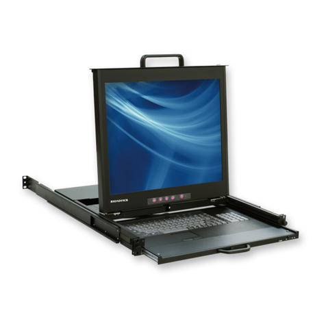
Broadrack Venus Series User manual

Venus Series
Stand Alone & Modular Combo-free KVM Switch
User Manual
Rev 2.0

Venus Series User Manual
I
Table of Contents
Table of Contents ................................................................................................ I
1. Introduction .................................................................................................. 1
1.1 Features ............................................................................................. 1
1.2 Package Contents .............................................................................. 3
1.3 Technical Specifications ..................................................................... 4
1.4 System Requirements ........................................................................ 8
1.5 Cable Diagrams................................................................................ 10
1.6 Rear Panel........................................................................................ 11
2. Hardware Installation ................................................................................ 13
2.1 Rack Mount Installation .................................................................... 13
2.2 Computer / Server Installation .......................................................... 15
2.3 Console Installation .......................................................................... 17
2.4 Optional Module Installation ............................................................. 17
2.5 Power ON......................................................................................... 19
2.6 CAT5 KVM Receiver (R-Box) ........................................................... 19
2.7 CAT5 Receiver Installation ............................................................... 19
2.8 When video signal is foggy or unclear.............................................. 19
2.9 Daisy Chain Connection................................................................... 20
3. Usage ........................................................................................................ 22
3.1 Buttons (Stand Alone KVM Switch Only).......................................... 22
3.2 Front panel PC port LED Indication (Stand Alone KVM Switch Only)22
3.3 BANK 7-seg LED (Stand Alone KVM Switch Only)........................... 23
3.4 Hot plug ............................................................................................ 23
4. Hotkey ....................................................................................................... 24
5. OSD (On Screen Display) ......................................................................... 26
5.1 Login Window ................................................................................... 27
5.2 Port Name ........................................................................................ 28
5.3 Main Menu........................................................................................ 29
5.3.1 LANGUAGE............................................................................ 29
5.3.2 PORT NAME EDIT ................................................................. 30
5.3.3 PORT SEARCH...................................................................... 31
5.3.4 USER SECURITY .................................................................. 31
5.3.5 ACCESS LIST ........................................................................ 32
5.3.6 HOTKEY................................................................................. 33
5.3.7 TIME SETTINGS .................................................................... 34
5.3.8 OSD MOUSE........................................................................ 34

Venus Series User Manual
II
6. Troubleshooting ......................................................................................... 36
7. Certifications .............................................................................................. 37

Venus Series User Manual
1
1. Introduction
The Venus series combo-free KVM switch can control attaching servers and
computers from local or remote console. This KVM switch is loaded with features
such as one local console port, plus one optional CAT5-based remote
console port or one optional IP-based remote console Port, On Screen
Display (OSD) Menu, Password security, Hot key Control, Push Button and Auto
Scan Control. It has complete keyboard and mouse emulation for simultaneous
PCs boot-up process.
With the CAT5-based remote console port you can you remotely control servers
and computers 1000 feet away. In other words, you can locate your monitor,
keyboard and mouse up to 1000 feet away from the KVM switch. The built-in
CAT5 transmitter synthesizes VGA monitor and keyboard/mouse signals, and
transmit the signals to the remote CAT5 receiver over the popular LAN CAT5
cable.
With the IP-based remote console port you can control one or many computers
locally at the server site or remotely via the Internet using a standard browser.
You can securely gain BIOS level access to systems for maintenance, support,
or failure recovery over the Internet. Communication is secure via SSL
encryption.
1.1 Features
Dual Console 8/16 ports KVM switch
Support combo interface for connecting to computer ports conveniently
Support one local console plus one optional remote console (CAT5 or IP)
CAT5 console up to 1000 feet away from KVM switch with superior
auto-adjust RGB gain/delay control capability
Support MS windows, Netware, Unix, and Linux
Support iMAC, Power MAC and Sun Micro Systems with USB port
No Software Required --- easy computer selection via On Screen Display
(OSD) Menu, Push Buttons, and Hotkeys
Provide various Hotkey (Scroll-Lock/ Cap-Lock/ Num-Lock/ L-Alt/ L-Ctrl/
L-Win/ R-Alt/ R-Ctrl/ R-Win) for switching computer port and other control
functions, so Hotkey function can be used in various types of keyboards,

Venus Series User Manual
2
and to avoid Hotkey duplicate problem.
Provide ACL (Access Control List) security function. Store up to 8
independent user accounts
Hot Plug --- add or remove connected computers without powering off the
KVM switch or computers
Support two user layers, and search computer/server name
Plug-n-Play monitor support
Keyboard status restored when switching computer
Support Daisy Chain function with both Bus (8-layer) and Tree (2-layer)
topologies

Venus Series User Manual
3
1.2 Package Contents
Venus 8 / 16 Series:
KVM Switch Unit 1 PCS
User’s Manual CD-ROM 1 PCS
Quick Setting Guide 1 PCS
12V DC Power Adapter 1 PCS
Rack Mount Kit 1 SET
KC-1515 Daisy Chain Cable (0.9 M) 1 PCS
KC-1501C Signal Cable (with USB Adapter) (1.8
M)
2 PCS
Table 1-1. Package Contents
Venus 8D / 16D Series:
KVM Switch Unit 1 PCS
Quick Installation Guide 1 PCS
LCD Console Mount Kit 1 SET
Table 1-2. Package Contents

Venus Series User Manual
4
1.3 Technical Specifications
Venus 8 / 16 Series:
Feature Specification
KVM Type PS/2 and USB interface KVM switch
Console Ports One local USB console
plus one optional remote module
PC Port Connector HDDB-15
PC Ports 8 / 16
Max. Distance
(KVM switch -- Host) 10 m (32 feet)
Video Resolution
(Local Console) 1920 x 1440
Video Resolution
(Remote Console)
1600 x 1200 for CAT5-Based 500 feet remote
console (R-Box),
1024 x 768 for CAT5-Based 1000 feet remote
console. (R-Box Enhanced),
1600 x 1200 for IP-Based remote console
CAT5-Based Remote
Console Module
RJ-45 Connector,
CAT5 console up to 1000 feet away from KVM
switch with superior, auto-adjust RGB gain/delay
control capability
IP-Based Remote
Module
RJ-45 8P8C for 10/100M Ethernet,
DB9 male for Modem, Null modem and serial
power control,
Mini USB 2.0 receptacle
Daisy Chaining Support Daisy Chaining with both Bus (8-layer) and
Tree (2-layer) topologies, DB15 Female Connector
Computer port
selection
On Screen Display (OSD) Menu, Hot Key, Push
Button
Hotkey Provide various Hotkey (Scroll-Lock/ Cap-Lock/
Num-Lock/ Alt/ Ctrl/ Win)
PC Port LEDs 2 x LEDs per PC port: Power (Green), Online (Red)
7-seg LED for Bank
display 1 set
Security Provide ACL (Access Control List) security

Venus Series User Manual
5
function, store up to 8 independent controllable
Computers lists
Multilingual OSD (On
Screen Display) control
8 languages (English, France, Germen, Spanish,
Italian, Russian, Japanese, Simplified Chinese)
Auto-Scan Intervals 5 ~ 99 Sec.
Keyboard Emulation PS/2 or USB
Mouse Emulation PS/2 or USB
Housing Metal
Power DC power adapter : DC 12V
Operation Temperature 0 ~ 50 ℃
Storage Temperature -20 ~ 60 ℃
Humidity 0 ~ 95%, Non-Condensing
Mechanical 19” Rack mount / 1U
Dimension 442 x 140 x 44 mm / 17.4 x 5.5 x 1.7 inches
Net Weight 3.0 Kg / 6.6 lbs
Table 1-3. Technical Specifications
Figure 1-1. Venus 8 / 16 Series Dimensions

Venus Series User Manual
6
Venus 8D / 16D Series:
Feature Specification
KVM Type PS/2 and USB interface KVM switch
Console Ports One local USB console
plus one optional remote module
PC Port Connector HDDB-15
PC Ports 8 / 16
Max. Distance
(KVM switch -- Host) 10 m (32 feet)
Video Resolution
(Local Console)
By LCD console panel video resolution
Maximum up to 1920 x 1440
Video Resolution
(Remote Console)
1600 x 1200 for CAT5-Based 500 feet remote
console (R-Box),
1024 x 768 for CAT5-Based 1000 feet remote
console. (R-Box Enhanced),
1600 x 1200 for IP-Based remote console
CAT5-Based Remote
Console Module
RJ-45 Connector,
CAT5 console up to 1000 feet away from KVM
switch with superior, auto-adjust RGB gain/delay
control capability
IP-Based Remote
Module
RJ-45 8P8C for 10/100M Ethernet,
DB9 male for Modem, Null modem and serial
power control,
Mini USB 2.0 receptacle
Daisy Chaining Support Daisy Chaining with both Bus (8-layer) and
Tree (2-layer) topologies, DB15 Female Connector
Computer port
selection On Screen Display (OSD) Menu, Hot Key
Hotkey Provide various Hotkey (Scroll-Lock/ Cap-Lock/
Num-Lock/ Alt/ Ctrl/ Win)
Security
Provide ACL (Access Control List) security
function, store up to 8 independent controllable
Computers lists
Multilingual OSD (On
Screen Display) control
8 languages (English, France, Germen, Spanish,
Italian, Russian, Japanese, Simplified Chinese)
Auto-Scan Intervals 5 ~ 99 Sec.

Venus Series User Manual
7
Keyboard Emulation PS/2 or USB
Mouse Emulation PS/2 or USB
Housing Metal
Power DC power adapter : DC 12V
Operation Temperature 0 ~ 50 ℃
Storage Temperature -20 ~ 60 ℃
Humidity 0 ~ 95%, Non-Condensing
Mechanical For modular LCD console use / 1U
Dimension 420 x 170 x 44 mm / 16.5 x 6.7 x 1.7 inches
Net Weight 2.0 Kg / 4.4 lbs
Table 1-4. Technical Specifications
Figure 1-2. Venus 8D / 16D Series Dimensions

Venus Series User Manual
8
1.4 System Requirements
Stand Alone Combo-free KVM Switch:
Model No. Venus 8 Series
Local Console side One VGA Monitor
One USB Keyboard
One USB Mouse
Computer side 8 x HDDB-15 pin male to one HDDB-15 pin
with two Mini Din 6 pin and one USB adapter
IP module One CAT5 cable
Network access environment
CAT5 module One CAT5 cable
R-Box (CAT5 KVM extender receiver)
One VGA Monitor
One USB Keyboard
One USB Mouse
Optional computer
Table 1-5. System Requirements
Model No. Venus 16 Series
Console side One VGA Monitor
One USB Keyboard
One USB Mouse
Computer side 16 x HDDB-15 pin male to one HDDB-15 pin
with two Mini Din 6 pin and one USB adapter
IP module One CAT5 cable
Network access environment
CAT5 module One CAT5 cable
R-Box (CAT5 KVM extender receiver)
One VGA Monitor
One USB Keyboard
One USB Mouse
Optional computer
Table 1-6. System Requirements

Venus Series User Manual
9
Modular Combo-free KVM Switch:
Model No. Venus 8D Series
Computer side 8 x HDDB-15 pin male to one HDDB-15 pin
with two Mini Din 6 pin and one USB adapter
IP module One CAT5 cable
Network access environment
CAT5 module One CAT5 cable
R-Box (CAT5 KVM extender receiver)
One VGA Monitor
One USB Keyboard
One USB Mouse
Optional computer
Table 1-7. System Requirements
Model No. Venus 16D Series
Computer side 16 x HDDB-15 pin male to one HDDB-15 pin
with two Mini Din 6 pin and one USB adapter
IP module One CAT5 cable
Network access environment
CAT5 module One CAT5 cable
R-Box (CAT5 KVM extender receiver)
One VGA Monitor
One USB Keyboard
One USB Mouse
Optional computer
Table 1-8. System Requirements

Venus Series User Manual
10
1.5 Cable Diagrams
PC Port Special Cable:
HDDB-15 pin male to one HDDB-15 pin male with two Mini Din 6 pin and one
USB adapter
Figure 1-3. HDDB-15 / VGA + PS/2 x 2 (1.8M)
PS/2 Keyboard to USB Adapter
PS/2 keyboard to USB keyboard and mouse due HID adapter
Figure 1-4. PS/2 Keyboard to USB Adapter
Daisy Chain Cable:
VGA Cable:
HDDB-15 pin Male to Male
Figure 1-5. Daisy Chain Cable
Daisy chain needs the cable all 15 lines connected. This is a
special VGA cable, normal VGA cable has unconnected lines. Do
not use other VGA cable for daisy chain.
CAT5/5E/6 Straight Through UTP/STP Cable
Figure 1-6. CAT5/5E/6 Straight Through UTP/STP Cable (8P8C)

Venus Series User Manual
11
1.6 Rear Panel
Venus 8:
Venus 16:
Venus 8 IP:
Venus 16 IP:
Venus 8 C5:
Venus 16 C5:
Venus 8D:
Venus 16D:
Venus 8D IP:

Venus Series User Manual
12
Venus 16D IP:
Venus 8D C5:
Venus 16D C5:
Figure 1-7. Rear Panel
Venus 16 C5:
Venus 16D C5:
Figure 1-8. Rear Panel
Local Console Keyboard / Mouse Ports
Local Console VGA Port / Daisy Chain port
Daisy Chain In
Connector for each Host Port
Remote Console Port (CAT5 Module)
DC Power Jack
Daisy Chain In
Connector for each Host Port
Remote Console Port (CAT5 Module)
DC Power Jack

Venus Series User Manual
13
2. Hardware Installation
Before installation, please make sure all of peripherals and computers have
been turned off.
2.1 Rack Mount Installation
Stand Alone KVM Switch:
Find a convenient place to put your KVM Switch. The 19” rack mount form factor
makes it ideally mountable on a 19” rack. When mounting to a rack, attach the
included brackets to the sides of the KVM Switch. Take note of the length of your
cables so that your computers, KVM Switch, keyboard, mouse and monitor are
distanced properly.
Figure 2-1. Rack Mount Installation
Modular KVM Switch:
Please open the package carefully and take out all required accessories to
prepare fluent installation. The modular KVM switch is for Gemini and Unicorn
use, please install the brackets with thumb screw. Please measure the suitable
distance between KVM switch and computer, keyboard, monitor and mouse
before installation.
Figure 2-2. Modular KVM Switch Usage Diagram

Venus Series User Manual
14
Install Modular KVM Switch Steps:
1. Install two screws (length = 6 mm) to combine bracket and KVM switch. (Both
sides)
2. Push KVM switch into the rails from rear of console.
3. Tight thumb screw of bracket up to fix KVM switch in console (Both sides) and
finish installation.
Rear view of rail
Plastic rail of KVM switch

Venus Series User Manual
15
2.2 Computer / Server Installation
Stand Alone KVM Switch:
Modular KVM Switch:
Figure 2-3. Computer / Server Installation

Venus Series User Manual
16
3-in-1 HDDB-15 Cable Installation
Each computer port connector is HDDB-15 type. Inspect the 3-in-1 DB15 cable.
It will have a HDDB-15 male connector at one end. Plug it into computer port on
the rear of KVM switch. The other end of input cable has three connectors: a
HDDB-15 male type for computer video, a purple mini din 6-pin PS/2 connector
for keyboard and a green mini din 6-pin PS/2 connector for mouse. Plug these
three connectors into the respective ports of computer. Repeat the same
procedure for all other computers.
a. PS/2 computer --- Plug PS/2 mouse connector to computer mouse port and
PS/2 keyboard connector to computer keyboard port. Do not hot plug PS/2 port.
If you must do that make sure PS/2 mouse first then the PS/2 keyboard.
Figure 2-4. 3-in-1 HDDB-15 Cable
b. USB computer --- Connect PS/2 connector of 3-in-1 HDDB-15 cable and USB
adapter. Plug USB connector to computer USB connector. This single USB
connector can handle both keyboard and mouse data, it work as a standard HID
(Human Interface Device) no extra driver needed.
Figure 2-5. 3-in-1 HDDB-15 Cable with USB Adapter
USB adapter

Venus Series User Manual
17
2.3 Console Installation
Local Console (Stand Alone KVM Switch Only)
Connect the monitor to the HDDB-15 female port on the back of the KVM unit
labeled with the monitor symbol at the Local Console connector.
There may be USB local console or PS/2 local console. For USB local console,
connect the USB keyboard to either one of USB local port and USB mouse to
the other USB port. These USB ports are special designed for keyboard and
mouse, and can not work with USB hub or other USB devices. For PS/2 local
console, connect keyboard to purple PS/2 port and mouse to green PS/2 mouse
port. There is a Daisy chain port under VGA ports.
Figure 2-6. Console Installation
2.4 Optional Module Installation
IP Module
Please refer to “IP KVM Module User Manual” for details.
IP Remote Console
Installation: Power off the KVM switch firstly. Remove the cover of the add-on
slot, slide in the IP Module and make sure the module is fully inserted into the
slot.
The IP Module redirects local keyboard, mouse and video data to a remote
administration console. It allows you to control one or many computers locally at
the server site or remotely via the Internet using a standard browser.
Table of contents
Other Broadrack Switch manuals

Broadrack
Broadrack Jupiter Series User manual

Broadrack
Broadrack Mercury Series User instructions

Broadrack
Broadrack Venus Operating instructions

Broadrack
Broadrack Mars series User manual

Broadrack
Broadrack Mercury 8 / 16 User manual

Broadrack
Broadrack Venus 8 / 16 User instructions

Broadrack
Broadrack KSR Series User manual

Broadrack
Broadrack Mars 8 User instructions

Broadrack
Broadrack Mars 8 User manual