BroaMan DiViNe Route66 User manual

DiViNe – Digital Video Network
Operating Manual
Rev. 1.0
Operating Manual for
DiViNe Route/Repeat 66/33
Digital Video Network device with Optocore and SANE
© Copyright 2011 All rights reserved
BROAMAN GmbH
Lohenstr. 8
82166 Munich-Gräfelfing
Germany

DiViNe Route/Repeat 66/33
2
rev. 1.0
Important Safety Instructions
•Please read this operating manual carefully.
•Please keep this operating manual in a safe place.
•Heed to all warnings.
•Follow all instructions.
•This device may only be used in accordance to the information provided in this operating
manual. Ensure that all recommendations detailed in this operating manual, especially the
safety recommendations, are followed before and during use of the device.
•Do not use this device near water and liquids, for example, in humid or damp rooms.
•Clean only with a dry cloth.
•Do not block or cover any ventilation openings. Install the device in accordance with the
operating manual.
•Do not install or place the device near a source of heat. Such as: radiators, power-amplifiers,
or any other heat emitting device.
•Protect the power cord from being stepped on, crushed, pinched or damaged in any other way
or form. Pay special attention to the plugs and sockets of the device.
•Do not place this device on an unstable table, tripod, cart, etc. The device may fall, causing
serious damage to the device.
•The device can be disconnected from the power supply by unplugging the power cord. The
power cords must be freely accessible at all times. The device should be disconnected during
lightning storms or when the device is unused for a long period of time.
•The device must be grounded. Disconnecting the ground is strictly prohibited.
•The internal components of the switched-mode power supplies operate at very high voltages.
Coming into contact with the power supplies can lead to considerable electric shock, which
may result in death.
•Only use attachments and accessories that are specified by the manufacturer of the device.
•This device contains no user serviceable parts. Please consult with authorised service
personnel before attempting to carry out any repair or modification of the device.
•Your warranty will be voided if you tamper with the internal components of the device.

DiViNe Route/Repeat 66/33
3
rev. 1.0
Owner Information
•Operating Manual
Please read this manual. If you call for technical support, we will assume that you have already done
so. Study the operating manual carefully in order to familiarise yourself with the device and its
operation. The operating manual contains important information and tips on proper use of the device.
It cannot be guaranteed that this operating manual does not include typographical mistakes or
misprints. The operating manual is regularly revised and updated.
Modifications, which serve the purpose of technical improvement of the device, may be carried out
without prior notification.
•Transport and Shipping
Always ensure careful handling of the device. If possible, transport and shipping of the device should
always be carried out in shock-absorbing transport cases. If these are not available, we recommend
well-padded packaging such as the coated carton in which the device was delivered.
We strongly advise against the use of light weight flight-cases without shock-absorbing rack-in-rack
mounting.
•Operational Environment
This device can be operated in E1, E2, E3, E4, or E5 environments (as listed below) according to the
harmonised European standards EN55103-1 and EN55103-2 “Electromagnetic compatibility –
Product family standard for audio, video and audio-visual and entertainment lighting control
apparatus for professional use”
E1-Residental
E2-Commercial and light industrial
E3-Urban outdoors
E4-Controlled EMC environment e.g. broadcast and TV-studio
E5-Heavy industry
The product is intended for use in moderate climates.
•Ventilation
Do not block or cover any ventilation openings. Install the device in accordance with the operating
manual. Allow for sufficient space around the units (at least 200 mm ≡7,87" free space behind the
rear-panel of the device) and make sure to allow for air circulation near the ventilation openings on
both sides of the device. Keep the rear of the rack open during operation. Do not operate the device
close to heat emitting equipment, such as power-amplifiers. Leave sufficient space (minimum ½ RU)
between the device and any heat emitting devices housed in the same rack. A Route/Repeat 66/33
device may be placed on top or beneath other BroaMan products, without a space between the
devices.
•Water and Moisture etc.
To prevent fire or shock hazard, do not expose the device to direct sunlight, dust, water or rain during
operation or storage.
•Cleaning
To clean the device, use a dry linen cloth. If the unit is very dirty, lightly moisten a cloth using water
and a small amount of household detergent. Never use cleaning agents containing solvents to clean
the device.
•Operating and Storage Temperature
Operating temperature: -20
°
C …50
°
C ≡-4
°
F … 122
°
F; ensure proper ventilation
Storage temperature: -20
°
C …60
°
C ≡-4
°
F … 140
°
F

DiViNe Route/Repeat 66/33
4
rev. 1.0
•Power Supply
The device can be disconnected from the power supply by unplugging the power cord. The power
cords must be freely accessible at all times. The device should be disconnected during lightning
storms or when the device is unused for a long period of time.
Please note:
The switched-mode power supplies operate with very high voltages. Coming into contact with
the power supplies can lead to considerable electric shock, which may result in death.
Never disconnect the power plug by pulling the cable. Always unplug the device.
Power-supply cords should be routed in such a way that they are not likely to be walked on, crushed,
pinched, or damaged in any other way or form. Pay special attention to the plugs and the sockets of
the device.
Please note:
A damaged power cable should be replaced immediately.
Please note:
The device must be grounded. Disconnecting the ground is strictly prohibited. Always ensure
that the device is grounded via the mains plug. Do not cover the grounding terminal of the
plug with any kind of insulation material!
•Fuse
There is no fuse in the device. The power supplies contain circuitry that protects the device from
overload.
•Lightning
For additional protection of this device during lightning storms, or when it is left unattended and
unused for a long period of time, disconnect the power cord. This will prevent damage to the device
due to lightning and power line surges. Disconnection from the mains power supply is only possible
by disconnecting the power plug from the mains socket.
•External objects and/or liquids
Never insert objects of any kind into the device through openings in the device chassis. The objects
may come into contact with dangerous voltages or create short circuits that can result in a fire or
electric shock. Never spill liquid of any kind on the device.
•Cables and Accessories
Only use attachments that are specified by the manufacturer of the device.
Use high quality, properly terminated, cables to connect the device. The device should only be used
with the optical fibre cables that are specified for use with the devices optical transceivers and within
the specified power budget of the optical transceivers. When not in use, ensure that the optical
connectors of both the device and the optical fibre cable are covered with the provided caps.
Do not place this device on an unstable table, tripod, cart, etc. The device may fall, which can cause
injury and serious damage to the device. Any mounting of the device should follow the
manufacturer’s instructions, and should use mounting accessories recommended by the
manufacturer of the device.
•Service and repairs
Do not attempt to service the device by yourself.
The device contains no user serviceable parts, components or controls. The operation of an opened
device is not permitted. Such operation can lead to damage of the device’s components due to the
absence of the required air flow through the device.
The device may not be serviced, altered or modified without authorisation from BroaMan or a
BroaMan authorised distributor / dealer. Only qualified service personnel may carry out repair and
maintenance work on the device. The warranty of the device will be voided if any unauthorised
maintenance or repair work has been carried out.

DiViNe Route/Repeat 66/33
5
rev. 1.0
CE Conformity
This document confirms that the product DiViNe Route/Repeat 66/33 bearing the CE (Communauté Européenne)
label meets all requirements in the EMC directive 2004/108/EG laid down by the Member States Council for
adjustment of legal requirements. Furthermore the product complies with the rules and regulations of the low-
voltage directive 2006/95/EG. This product bearing the CE label complies with the following standards, ratified by
CENELEC (Comité Européen de Normalisation Electrotechnique):
Electromagnetic compatibility – Product family standard for audio, video, audio-visual and
entertainment lighting control apparatus for professional use
EN 55103-1, Emission
EN 55103-2, Immunity
The authorised declaration and compatibility certification lies with the manufacturer and can be viewed on
request. Responsible as manufacturer is:
BROAMAN GmbH, Lohenstr. 8, 82166 Munich-Gräfelfing, Germany
represented by Marc Brunke, Managing Director
N.B. The awarding of the CE label confirms the compliance with legal directives issued for the manufacturer and
marketing of electronic and electrical devices. As such the CE label is not a "seal of quality" but rather proof that
the device bearing the CE label conforms with the electromagnetic compatibility standards laid down in the above
named testing regulations.
Munich, 01.10.2011
Marc Brunke

DiViNe Route/Repeat 66/33
6
rev. 1.0
DiViNe Route/Repeat 66/33
Digital Video Network unit with Optocore and SANE
Table of Contents
Important Safety Instructions....................................................................................................................................2
Owner Information....................................................................................................................................................3
CE Conformity..........................................................................................................................................................5
Device Description...................................................................................................................................................7
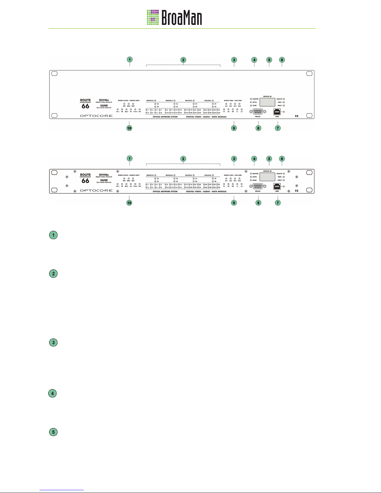
Front Panel...............................................................................................................................................................8
2RU frame.....................................................................................................................................................8
1RU frame.....................................................................................................................................................8
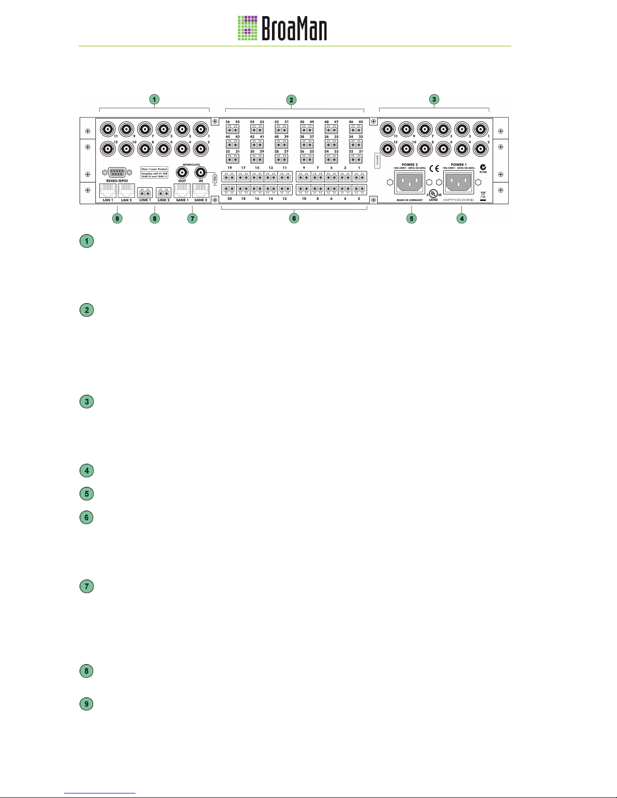
Rear Panel.............................................................................................................................................................10
2RU frame...................................................................................................................................................10
1RU frame...................................................................................................................................................11
Device Details........................................................................................................................................................12
Video BNC Ports.........................................................................................................................................12
Video Fibre Ports........................................................................................................................................12
Routers.......................................................................................................................................................12
Multiplexers.................................................................................................................................................12
Optocore Fibre Optic Connection................................................................................................................12
SANE Ports.................................................................................................................................................12
RS485/GPIO Auxiliary Ports.......................................................................................................................12
Word Clock .................................................................................................................................................13
Optocore Transmission Delay.....................................................................................................................13
Power Supply..............................................................................................................................................13
Control....................................................................................................................................................................13
Connectors and Cables..........................................................................................................................................14
SD/HD/3G-SDI Ports ..................................................................................................................................14
Optical Connections....................................................................................................................................14
SANE Ports.................................................................................................................................................14
Auxiliary Ports – R485/GPIO.......................................................................................................................14
RS232 Connection......................................................................................................................................14
Connector Hood Quality..............................................................................................................................14
USB Connection .........................................................................................................................................15
LAN Connection..........................................................................................................................................15
Word Clock Connection..............................................................................................................................15
Power Connection.......................................................................................................................................15
Connection Example..............................................................................................................................................16
Connector Pinouts..................................................................................................................................................17
Technical Specifications.........................................................................................................................................18
Dimensions and Weight .........................................................................................................................................19
Warranty and Liability.............................................................................................................................................20
Package Contents..................................................................................................................................................20
Company Information.............................................................................................................................................21

DiViNe Route/Repeat 66/33
7
rev. 1.0
Device Description
Congratulations on your purchase of a DiViNe Route/Repeat 66/33 - SD/HD/3G-SDI to/from fiber video -
Router/Repeater with Optocore and SANE. The Route/Repeat 66/33 manual, accompanied with the DiViNe
system manual, will quickly demonstrate the advantages of the device and help ease your day to day workload in
the professional audio visual industry.
DiViNe, the Digital Video Network, provides scalable, protocol independent, routing, repeating, transport and
distribution of multiple professional video signals over optical fibre.
Complete DiViNe systems are built from a collection of modules that include; coaxial and optical I/O, routers,
repeaters, and optical multiplexers. Using the modular DiViNe building blocks, any system configuration can be
realized.
DiViNe systems are specified and built to provide an engineered system solution, tailored to the requirements of
the customer. The modular nature of DiViNe paves the way for construction of fully cost optimized systems.
The cornerstones of DiViNe systems are Route66, Route33, Repeat66 and Repeat33. The devices are capable of
66 and 33 channels of routing, signal repeating, as well as signal conversion between electrical and optical.
Route/Repeat 66/33 devices can be customized to meet the most sophisticated requirements.
Route/Repeat 66/33 are signal independent and can be used to route and repeat signals such as SD/HD/3G-SDI,
MADI, Ethernet, Optocore as well as optical signals from third party converters.
The devices are built from 1RU or 2RU frames, depending on the quantity and type of electrical and fibre
interfaces required.
2RU frames can be equipped with up to 24 BNC ports for SD/HD/3G-SDI video, 20 duplex LC fibre ports, and up
to 36 simplex LC fibre ports.
1RU frames can be equipped with up to 10 BNC ports for SD/HD/3G–SDI video and up to 8 simplex LC fibre
ports.
SD/HD/3G-SDI I/O options include: input with adaptive EQ, input with reclocker, output, output with reclocker and
a switchable I/O.
Route/Repeat 66/33 can be equipped with video clock output modules. The clock outputs are derived from a
synchronized video source in the system.
CWDM multiplexer modules can be installed in Route/Repeat 66/33.
Route/Repeat 66/33 may be equipped with an Optocore FX module. The low latency, synchronous, Optocore
network provides the capability of transporting, and patching, up to 1024 audio inputs into thousands of outputs,
over a redundant network. Additionally, the Optocore FX module includes 64 channel SANE audio ports on Cat5,
4 RS485/422 ports, 100Mbit Ethernet switch and a Word Clock input and output.
Route 66/33 devices can be configured as switched or automatic Optocore routers, providing the capability to
build Optocore networks in a star topology or as a mixture of ring- and star topology.
Route/Repeat 66/33 are populated with routers, I/O and multiplexers at the time of manufacturing, according to
customer’s specifications.
Route 66/33 can be controlled by an external controller or by using automated routing, according to customer’s
specifications.
Route/Repeat 66/33 are equipped with a built-in redundant power supply with an automatic switchover.
The front panels of the Route/Repeat 66/33 units are identical, independent of the hardware configuration. The
layout of the rear panel is dependent upon the configuration of the device.
Please note:
Refer to the DiViNe System Manual for detailed system specifications and functionality.

DiViNe Route/Repeat 66/33
8
rev. 1.0
Front Panel
2RU frame
1RU frame
Word Clock LED: Indicates the selected word clock source:
INT: Internal word clock
BNC: External via the BNC WC input
AES: External via AES (available upon request)
Router status LED: Indicates that the device is configured to work as a:
Repeat33: 33 channel video repeater
Repeat66: 66 channel video repeater
Route33: 33 channel video router
Route66: 66 channel video router
ACT LED: Signal indication on channels 1-40:
LED ON: Signal is present
LED OFF: No signal is present
AUDIO LINK:
SL1: Communication is established via SANE 1 (rear panel)
SL2: Communication is established via SANE 2 (rear panel)
OL1: Communication is established via Optocore LINK 1 (rear panel)
OL2: Communication is established via Optocore LINK 2 (rear panel)
Master LED: Indicates the master device in the system
OPTO LED: Optocore communication is established
SANE LED: SANE communication is established
Device ID Display: The identification number (ID) of the device

DiViNe Route/Repeat 66/33
9
rev. 1.0
HEALTH LED: Green: Power supply to the device is working, temperature is within limits
PWR 1 LED: Green: Power supply 1 is receiving power and working
PWR 2 LED: Green: Power supply 2 is receiving power and working
USB connector: USB connection for remote control via PC
USB LED: Green: Indicates data activity
RS232 connector: RS232 (D-Sub-9) connection for remote control and firmware updates via PC
LAN LINK:
S1: Ethernet communication is established via SANE 1 (rear panel)
S2: Ethernet communication is established via SANE 2 (rear panel)
UP: There is another device with an enabled Ethernet port on the network
L1: Ethernet communication is established via LAN 1 (rear panel)
L2: Ethernet communication is established via LAN 2 (rear panel)
Sample rate LED: Yellow: 44.1 / 48 / 88.2 / 96 / 176.4 / 192 kHz

DiViNe Route/Repeat 66/33
10
rev. 1.0
Rear Panel
2RU frame
Video ports 1-12: Can be populated with up to 12 SD/HD/3G-SDI video ports
Each port can be configured by the manufacturer as:
• Input with an optional reclocker or equalizer
• Output with an optional reclocker
• Blackburst output, derived from a specified video source within the system
Fibre ports 21-56: Can be populated with up to 36 fibre ports with TX and/or RX
Each port can be configured by the manufacturer as:
• Simplex transmitter / receiver for use with video
• Duplex transceiver for use with bidirectional communication links such as
Optocore (when the device is used as an Optocore Router), MADI etc.
• Connection to and from WDM multiplexers. For WDM common inputs and
outputs, auxiliary ports for use with Optocore etc.
Video ports 13-24: Can be populated with up to 12 SD/HD/3G-SDI video ports
Each port can be configured by the manufacturer as:
• Input with an optional reclocker or equalizer
• Output with an optional reclocker
• Blackburst output, derived from a specified video source within the system
POWER 1: Mains input for power supply 1 (100 … 240 V)
POWER 2: Mains input for power supply 2 (100 … 240 V)
Fibre SFP ports 1-20: Can be populated with up to 20 user changeable SFP fibre ports with TX and
RX. Each port can be configured by the manufacturer as:
• Simplex transmitter / receiver for video
• Duplex transceiver for use with bidirectional communication links such as
Optocore (when the device is used as an Optocore Router), MADI etc.
Word Clock IN: BNC Word clock input allows synchronization of Optocore devices from an
external word clock source
Word Clock OUT: BNC Word clock output for synchronization of external devices
SANE 1: SANE RJ-45 interface for audio transmission and 100 Mbit Ethernet
SANE 2: SANE RJ-45 interface for audio transmission and 100 Mbit Ethernet
LINK 1: Full-duplex, full bandwidth LC-type optical interface for Optocore transmission
LINK 2: Full-duplex, full bandwidth LC-type optical interface for Optocore transmission
RS485/GPIO: 4 x RS485/GPIO (D-Sub-9) auxiliary port for data transmission
LAN 1: 100 Mbit RJ-45 Ethernet interface
LAN 2: 100 Mbit RJ-45 Ethernet interface

DiViNe Route/Repeat 66/33
11
rev. 1.0
1RU frame
RS485/GPIO: 4 x RS485/GPIO (D-Sub-9) auxiliary port for data transmission
Word Clock IN: BNC Word clock input allows synchronization of Optocore devices from an
external word clock source
Word Clock OUT: BNC Word clock output for synchronization of external devices
Video ports 1-10: Can be populated with up to 10 SD/HD/3G-SDI video ports
Each port can be configured by the manufacturer as:
• Input with an optional reclocker or equalizer
• Output with an optional reclocker
• Blackburst, output derived from a specified video source within the system
POWER 1: Mains input for power supply 1 (100 … 240 V)
POWER 2: Mains input for power supply 2 (100 … 240 V)
Fibre ports 1-8: Can be populated with up to 8 fibre ports with TX and/or RX
Each port can be configured by the manufacturer as:
• Simplex transmitter / receiver for video
• Duplex transceiver for use with bidirectional communication links such as
Optocore (when the device is used as an Optocore Router), MADI etc.
• Connection to and from WDM multiplexers. For WDM common inputs and
outputs, auxiliary ports for use with Optocore etc.
SANE 1: SANE RJ-45 interface for audio transmission and 100 Mbit Ethernet
SANE 2: SANE RJ-45 interface for audio transmission and 100 Mbit Ethernet
LINK 1: Full-duplex, full bandwidth LC-type optical interface for Optocore transmission
LINK 2: Full-duplex, full bandwidth LC-type optical interface for Optocore transmission
LAN 1: 100 Mbit RJ-45 Ethernet interface
LAN 2: 100 Mbit RJ-45 Ethernet interface

DiViNe Route/Repeat 66/33
12
rev. 1.0
Device Details
Video BNC Ports
Each of the twenty-four (maximum for the 2RU frame) or ten (maximum for the 1RU frame) video I/O ports can be
equipped with a high quality BNC connector, providing SD/HD/3G-SDI connectivity.
Each SD/HD/3G-SDI video port can be configured by the manufacturer as:
• Input with an optional reclocker or equalizer
• Output with an optional reclocker
• Blackburst output derived from a specified video source within the system
Video Fibre Ports
Video from/to SD/HD/3G-SDI video ports can be routed or repeated to fibre ports. Video fibre ports may be
connected to an internal/external WDM module to multiplex/de-multiplex multiple video channels together with an
Optocore audio network. Each video port may be equipped with a different transceiver wavelength, allowing for
MUX and DEMUX.
Video Fibre Ports are configurable by the manufacturer as simplex TX or RX, depending on the requirements.
The fibre ports may also be configured as duplex fibre links for bidirectional communication protocols such as
Optocore (when the device is used as an Optocore Router), MADI etc.
Routers
The device can optionally be equipped with a Router by the manufacturer. The Router can have up to 66 or 33
ports. The ports are configured by the manufacturer, depending on the specified use of the device.
Multiplexers
The device can optionally be equipped with WDM multiplexer modules. CWDM, Coarse Wavelength Division
Multiplexer, and DWDM, Coarse Wavelength Division Multiplexer, modules are available and can be configured
for Mux and Demux by the manufacturer, depending on the specified use of the device.
External auxiliary Mux and Demux ports can be added to the device to provide external connectivity to the WDM.
Optocore Fibre Optic Connection
The device is equipped with the Optocore FX communication module. The OPTOCORE ® OPTICAL DIGITAL
NETWORK SYSTEM uses the Time Division Multiplex technology (TDM) with a Fibre Channel based 8B10B-
NRZI-coding. Static time slots guarantee a synchronous transmission of all channels, at all times, without the use
of dynamic bandwidth. All signals connected to the intercom, audio, video, word clock and auxiliary ports of the
device are transmitted simultaneously on one fibre while the second fibre of the LINK-Interface receives data from
the network. The second LINK-Interface pair is identical to the first one, and can optionally be used for network
redundancy.
SANE Ports
The device is equipped with two RJ45 200MBit SANE Ports, capable of transmitting 64 channels of synchronous
audio and 100MBit Ethernet.
RS485/GPIO Auxiliary Ports
The auxiliary ports provide four RS485 interfaces to establish a maximum of four half-duplex or two full-duplex
connections between devices. A wide range of bi-directional and unidirectional standards can be connected to the
ports, such as RS485, CAN-Bus (bi-directional), or RS422, DMX and MIDI (unidirectional).
The ports automatically sense whether they are sending or receiving control data.
The ports and their destinations are configured in the OPTOCORE CONTROL software.

DiViNe Route/Repeat 66/33
13
rev. 1.0
Word Clock
Devices with Optocore/SANE modules are equipped with an internal, high quality, low jitter clock as well as Word
Clock inputs and outputs. Any device on the network can act as the master of the network and pass Word Clock
to networked Optocore/SANE devices.
The internal/networked Word Clock is available at the Word Clock output connector of each device on the network
to synchronize non-networked devices.
In standalone network configurations external synchronization is not required.
The Word Clock input termination can be switched on using the OPTOCORE CONTROL software’s Local
Settings. No additional external termination is required to avoid cable reflections.
Optocore Transmission Delay
The Optocore system delay, including the matrix, is a fixed 41,6 µs @ 48 kHz for all channels. The additional
transport delay per Optocore unit on the network (<200 ns) is insignificant in comparison. Overall system delay is
dependent on the converters used and the length of network cables in the system. Assuming ‘normal’ cable
lengths of <700 m per link, the additional delay is considered marginal.
The transmission delay is constant between any points in the network.
Power Supply
The device is optionally equipped with two power inputs and power supplies. If the primary power supply were to
fail, due to disruption of the power source or in the case of a power supply malfunction, the device will
automatically switch over to the redundant power supply. In order to make the power supply to the device
redundant, both power inputs must be connected to the mains supply, if possible to different phases, circuits, or
even better, having one of the power supplies connected to an uninterrupted power supply (UPS).
The power supplies operate with mains voltage of 100 ... 240 V and frequency of 50 … 60 Hz. The device can be
used throughout the world without any modifications or transformers.
Please note:
The switched-mode power supplies operate at very high voltages! Coming into contact with the power
supplies can lead to considerable electric shock, which may result in death! To prevent electric shocks,
do not remove any covers of the device!
Control
A Route/Repeat 66/33 does not require software to be fully operable. Each unit is configured by the manufacturer
according to the requirements of the customer. No further configuration is necessary.
Signal routing can be to be preconfigured with automatic discovery and routing or controlled manually using a 3
rd
party integration control platform such as VSM by the company LSB.
Auxiliary port (RS485/422) settings and the device ID can be configured by the user using the Optocore Control
Software with a PC connected to the RS232, LAN or USB ports of the device.
For further information please contact the BroaMan technical support team.

DiViNe Route/Repeat 66/33
14
rev. 1.0
Connectors and Cables
SD/HD/3G-SDI Ports
Use 75 Ωcoaxial cable with BNC connectors. The cable and connectors used should comply with the digital
SD/HD/3G-SDI transmission standards. The maximum cable length is dependent on the bandwidth of the signal
(SD, HD or 3G) and the specifications of the cable and connectors.
Optical Connections
All optical ports can be equipped with duplex LC connectors using internal and external SFP (small form factor
pluggable) transceivers.
The 2RU frame can be equipped with up to 20 SFP transceivers by the manufacturer. Fibre ports 1-20 are full
duplex and transceivers can be changed by the user.
The 2RU frame fibre ports 21-56 can be equipped with internal SFP transceivers and configured as simplex or
duplex optical ports by the manufacturer.
The 1RU frame fibre ports 1-8 can be equipped with internal SFP transceivers and configured as simplex or
duplex optical ports by the manufacturer.
Please note:
The internal SFP transceivers should not to be changed by the user.
To change internal SFP transceivers, please contact the BroaMan technical support team.
For video applications:
Standard single mode transceivers connected using a 9 µm fibre cable can be used for applications requiring
cable lengths of up to 10 km (worst case).
Extended single mode transceivers connected using a 9 µm fibre cable can be used for applications requiring
cable lengths of up to 80 km (worst case).
For Optocore networks and routers:
Multimode transceivers connected using a 50 µm OM3 fibre cable can be used for applications requiring cable
lengths of up to 700 m (worst case).
Single mode transceivers connected using a 9 µm fibre cable can be used for applications requiring cable lengths
of up to 70 km (worst case).
The total optical loss should be less than 6dB between transceivers.
For portable applications, such as touring and other temporary installations, ruggedized HMA Expanded Beam
Connectors, mounted on 1 RU panels and portable cables on cable drums are available.
Please refer to the Product Brochure available at www.BroaMan.com.
SANE Ports
Use standard, fully wired, twisted pair cable (Cat 5, Cat 5e, Cat 6), terminated with RJ-45 connectors. SANE
utilizes all four pairs of the Cat-5 cable, two pairs for standard Ethernet transmission and two pairs for the SANE
audio transport.
Auxiliary Ports – R485/GPIO
Each of the four channels requires a shielded twisted pair cable.
If two or more channels are wired to the same cable a common braided shield should enclose the pairs.
RS232 Connection
Use a standard shielded RS232 cable.
Connector Hood Quality
Locking screws for D-Sub connectors must be according to 4-40 UNC. Care should be taken in selecting the right
type of connector hoods in order to fulfil the requirements of EMI-radiation directives. Full metal connector hoods
should be used, approved acc. to VDE 0871, FCC 20780 and EMC directive 2004/108/EG, providing a reduction
> 40 dB on 30 MHz up to 1 GHz. The shield of the cable should have contact to the connector hood.

DiViNe Route/Repeat 66/33
15
rev. 1.0
USB Connection
Use USB-A to USB-B cable between the PC and the device.
LAN Connection
Use a standard twisted pair cable (Cat-5, Cat-6) with RJ-45 connectors.
Word Clock Connection
Use 75 Ωcoaxial cable with BNC connectors.
Power Connection
Use power cords with IEC C13 connectors.

DiViNe Route/Repeat 66/33
16
rev. 1.0
Connection Example
This example shows the connections between one central Route66 and two portable Route33 units. The Route66
is configured as a 4 x 20 router, capable of sending four SD/HD/3G-SDI video channels to five different
connection points. It is possible to connect one of the two Route33 units at each connection point. Each of the
Route33s is equipped with two SD/HD/3G-SDI outputs and a BlackBurst output. The Route66 and the two
Route33s are connected with fibre cables. Routing can be fixed or operator controlled using a third party
integration controller, such as VSM by the company LSB.
Fig. 1: Connection of one Route66 and two Route33 units.
This example shows the use of Route66 and Route33s as a video only routing system. In this system, none of the
devices are equipped with an Optocore module for device discovery, automated routing, audio and data transport.

DiViNe Route/Repeat 66/33
17
rev. 1.0
Connector Pinouts
Pin-out Auxiliary Ports 4 x RS485
RS485
Channel 1 2 3 4 GND
+ 1 2 3 4
Pin - 6 7 8 9 5
Please assure correct polarity “+” and “-“
at both (!) sides / devices when connecting
external equipment to the RS485 ports.
D-Sub-9- female
5
1
9
6
Locking system acc. to 4-40 UNC
Pin-out RS232-Port
RS232 Power
Channel RXD TXD
Internally
bridged +5VS GND
Pin 3 2 1, 4, 6
7, 8 9 5
Use standard RS232 cable, male –
female, to connect to PC
D-Sub-9- female
5
1
9
6
Locking system acc. to 4-40 UNC
Pin-out USB-Port
USB
Channel VBUS
D - D + GND
Pin 1 2 3 4
USB device-connector

DiViNe Route/Repeat 66/33
18
rev. 1.0
Technical Specifications
Video
Standards SD, ED, HD, Dual Link, 3G
Complies with SMPTE 259M, 292M, 344M, 372M, 424M
Interface SDI – Serial Digital Interface
Optical Connection
Complies with 21 CFR 1040.10 and 1040.11
SANE, LAN
Convention
Audio TIA - 568A/B, Optocore 200 Mbit/s
LAN TIA - 568A/B, IEEE - 802.3 10/100 Mbit/s
Word clock
Hardware standard BNC - 75 Ω
Data rate Depending on selected sample rate Up to 192 kHz
Impedance Output ≤5 Ω
Input 75 Ω
Drive level Output ≥1 V
pp
Zero level Referring to GND + 1.7 V
Sense level Input ≥400 mV
pp
Remote Control
Convention
RS232 EIA / TIA - 232 57 600 Baud
USB USB 2.0 - Device 12 Mbit/s
LAN IEEE - 802.3 10/100 Mbit/s
Power supply
Type Switch-mode, universal input
Mains voltage 100 … 240 V
Frequency 50 … 60 Hz
Power consumption Depending on the configuration of the device, 32VA - Max
Security classification Class 1: basic insulation, connected to the protective grounding conductor
Security regulations Harmonised European standard EN60065
Mains connector acc. to IEC-950
Cooling Passive, via surface and ventilation openings on both sides of the device

DiViNe Route/Repeat 66/33
19
rev. 1.0
Dimensions and Weight
Dimensions
Front panel: width 483 mm / 19 inch
height 88 mm / 3.46 inch (2RU frame), 44 mm / 1.73 inch (1RU frame),
depth 200 mm / 7.87 inch
Rear panel: width 438 mm / 17.25 inch
Weight
Dependent on the configuration of each specific device.
Please note:
Modifications that serve the purpose of technical improvement may be carried out without prior
notification.

DiViNe Route/Repeat 66/33
20
rev. 1.0
Warranty and Liability
Summary of Warranty
The BroaMan Route/Repeat 66/33 warranty covers defects in material and workmanship for 24 months.
This warranty covers the original purchaser only and is not transferable. Valid evidence of warranty is the official
BroaMan invoice issued by the distributor / dealer.
BroaMan will, at its discretion, repair or replace a defective product, providing that the defect has occurred under
normal operating conditions.
This warranty does not cover damage from acts of God, accident, abuse, neglect, contamination, unauthorised
modification or misuse, operation outside of the environmental specifications for the product, improper site
preparation or maintenance, or abnormal conditions of handling. This would include over-voltage failures, and
conditions outside of the products specified ratings, problems with buyer-supplied software or interfacing, or
normal wear and tear of mechanical components. BroaMan, or its distributor / dealer, will acknowledge the
evaluation of warranty after inspection.
Devices on which the Serial Number has been removed or defaced are not eligible for warranty service.
Failure to properly package and protect the product during shipping may void this warranty.
How to Obtain Warranty Service
To return a defective product, please contact your distributor / dealer.
Our website: http://www.BroaMan.com/ provides a complete list of BroaMan distributors / dealers.
Always ensure the careful handling of the device. If possible, these devices should always be transported or
shipped in special, shock-absorbing transport cases. If these are not available, we recommend well-padded
packaging such as the coated carton in which the device was delivered.
We strongly advise against the use of simple flight-cases without rack-in-rack mounting.
Declaration of Liability
BroaMan accepts no liability for damage caused to other devices through operation of the Route/Repeat 66/33
device.
BroaMan is not liable for any damage caused by shipping accidents, misuse, abuse, operation with incorrect AC
voltage, operation with faulty peripheral equipment, or improper or careless installation of the device.
BroaMan accepts no claims for compensation whatsoever (e.g. cancellation of events).
Package Contents
Route/Repeat 66/33 is a part of the ordered system. Each Route/Repeat 66/33 package should consist of:
•1 Route/Repeat 33/66 unit
•1 operator manual
•2 power cables
Any additionally purchased equipment such as optical fibre cables in required lengths, D-Sub cables and
adapters, RS232 cables, and international electric cables which have been supplied on your request and your
purchase order, cannot be listed above.
A system manual is provided with each DiViNe system.
This manual suits for next models
3
Table of contents