3
Table of Contents
Table of contents
Safe Servicing Practices............................................................ 2
Grounding Instructions.............................................................. 2
Features....................................................................................... 4
Section A – Installation.............................................................. 5
Free-Standing............................................................................... 5
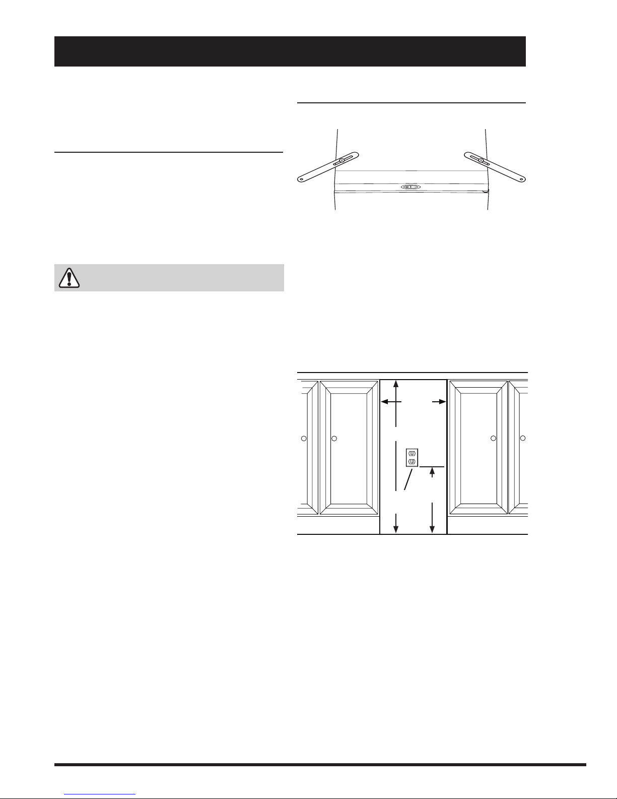
Built-In Installation ........................................................................ 5
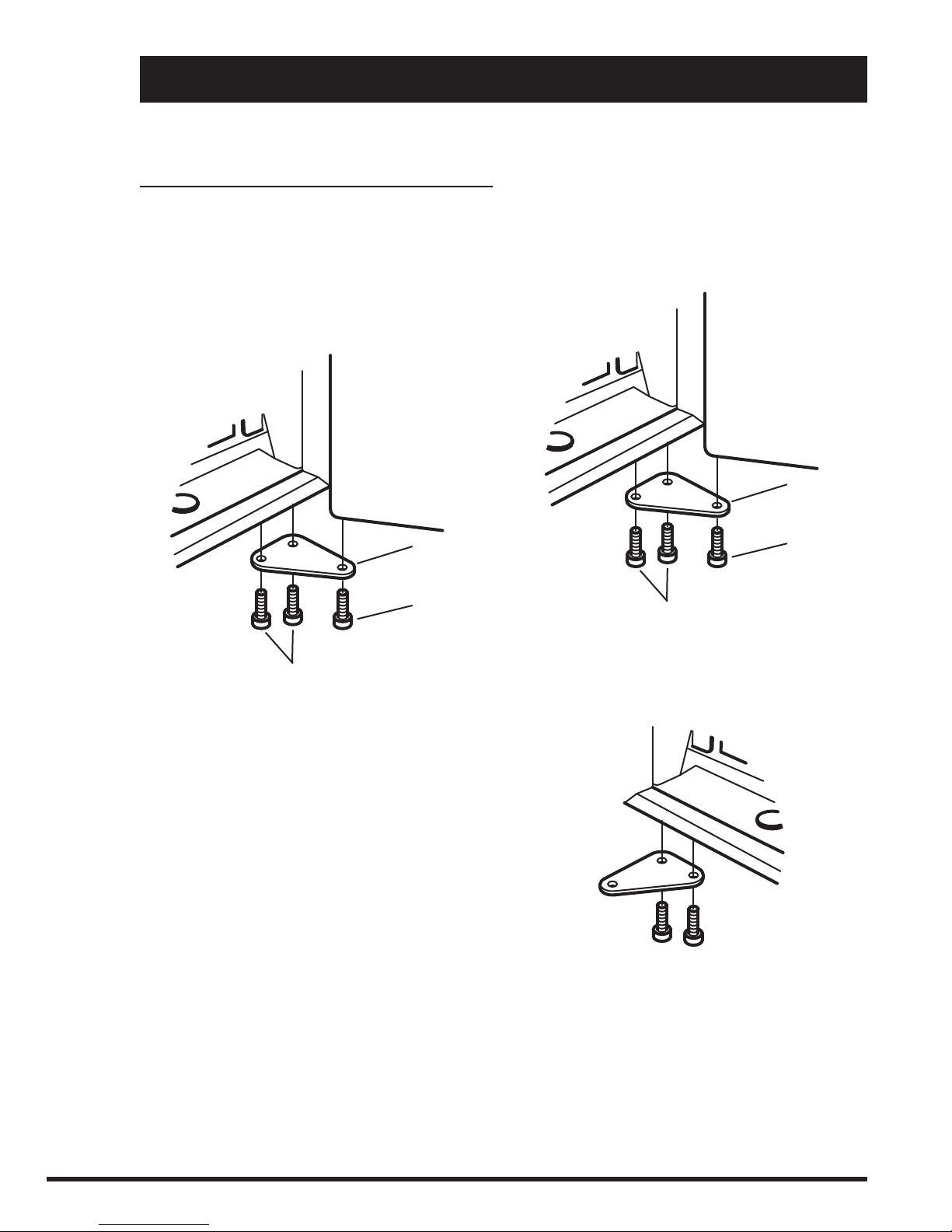
Mounting Straps....................................................................... 5
Under-Counter Opening .......................................................... 5
Cord Clamp ............................................................................. 6
Leveling the Compactor................................................................ 6
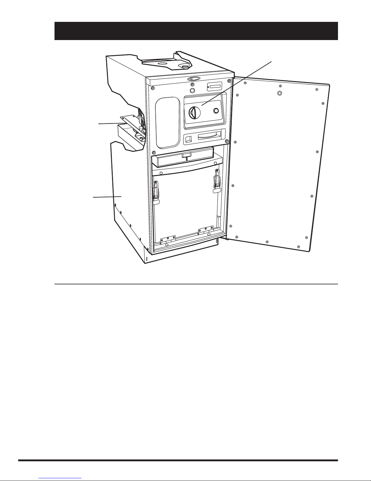
Section B – Cabinet.................................................................... 7
Trash Bucket................................................................................. 8
Remove ................................................................................... 8
Bucket Handle .............................................................................. 8
Remove and Replace .............................................................. 8
Slide Rails (Cabinet)..................................................................... 9
Remove and Re-install ............................................................ 9
Slide Rails (Bucket) ...................................................................... 9
Remove and Re-install ............................................................ 9
Door Assembly ............................................................................. 10
Remove and Re-install ............................................................ 10
Reverse Door Hinge Position................................................... 10
Safety Interlock Actuator .............................................................. 11
Remove and Re-install ............................................................ 11
Gasket Assembly.......................................................................... 12
Remove and Re-install ............................................................ 12
Top Trim Cover Assembly ............................................................. 13
Remove and Re-install ............................................................ 13
Section C – Power Unit Mechanism.......................................... 14
Drive Belt ...................................................................................... 15
Remove and Re-install ............................................................ 15
Main Motor.................................................................................... 16
Remove and Replace .............................................................. 16
Complete Power Unit Mechanism ................................................ 17
Remove and Re-install ............................................................ 17
Drive Wheels ................................................................................ 17
Remove and Replace .............................................................. 17
Ram Screw Assembly................................................................... 18
Remove and Replace .............................................................. 18
Section D – Electrical Components.......................................... 21
Start Switch .................................................................................. 22
Remove and Replace .............................................................. 22
Access to Components................................................................. 22
Remove Cabinet Cover............................................................ 22
Re-install Cabinet Cover.......................................................... 24
Control Panel Assembly ............................................................... 25
Remove and Re-install ............................................................ 25
Display Module Assembly............................................................. 26
Remove and Re-install ............................................................ 26
Key Switch.................................................................................... 26
Remove and Replace .............................................................. 26
Interlock Switch Assembly............................................................ 27
Remove and Re-install ............................................................ 27
Upper Limit Switch Assembly....................................................... 27
Remove and Replace .............................................................. 27
Lower Limit Switch........................................................................ 28
Remove and Replace .............................................................. 28
Motor Centrifugal Switch Assembly.............................................. 28
Remove and Replace .............................................................. 28
Motor Capacitor............................................................................ 29
Test, Remove and Replace...................................................... 29
Section E – Troubleshooting
Troubleshooting Table................................................................... 31
Section F – Specifications
Specifications Table ...................................................................... 34
Section G – Diagrams and Parts Lists
Wiring Schematic ......................................................................... 34
Drawing and Parts List – Cabinet ................................................ 35
Drawing and Parts List – Mechanism .......................................... 36