Brobo TNF-115 User manual

PRODUCT AND MAINTENANCE MANUAL
MANUAL
CUTTING SAW
Model No. TNF-115
YOUR BROBO WALDOWN DISTRIBUTOR IS:
BROBO WALDOWN (AUST) PTY. LTD.
A.C.N. 098 264 316
A.B.N. 42 098 264 316
65-67 Williams Rd, Dandenong, 3175
PO BOX 4274 Dandenong Sth, 3164
Victoria, AUSTRALIA.
Tel: 61 3 9794 8751 Email: info@brobo.com.au
Fax: 61 3 9794 8792 Website: www.brobo.com.au
Certified System
Quality
ISO 9001

page. 1/ 23
1
INTRODUCTION
INDEX
1. INTRODUCTION ............................................................................................................................... 2
2. SAFETY APPLICATIONS..................................................................................................................... 3
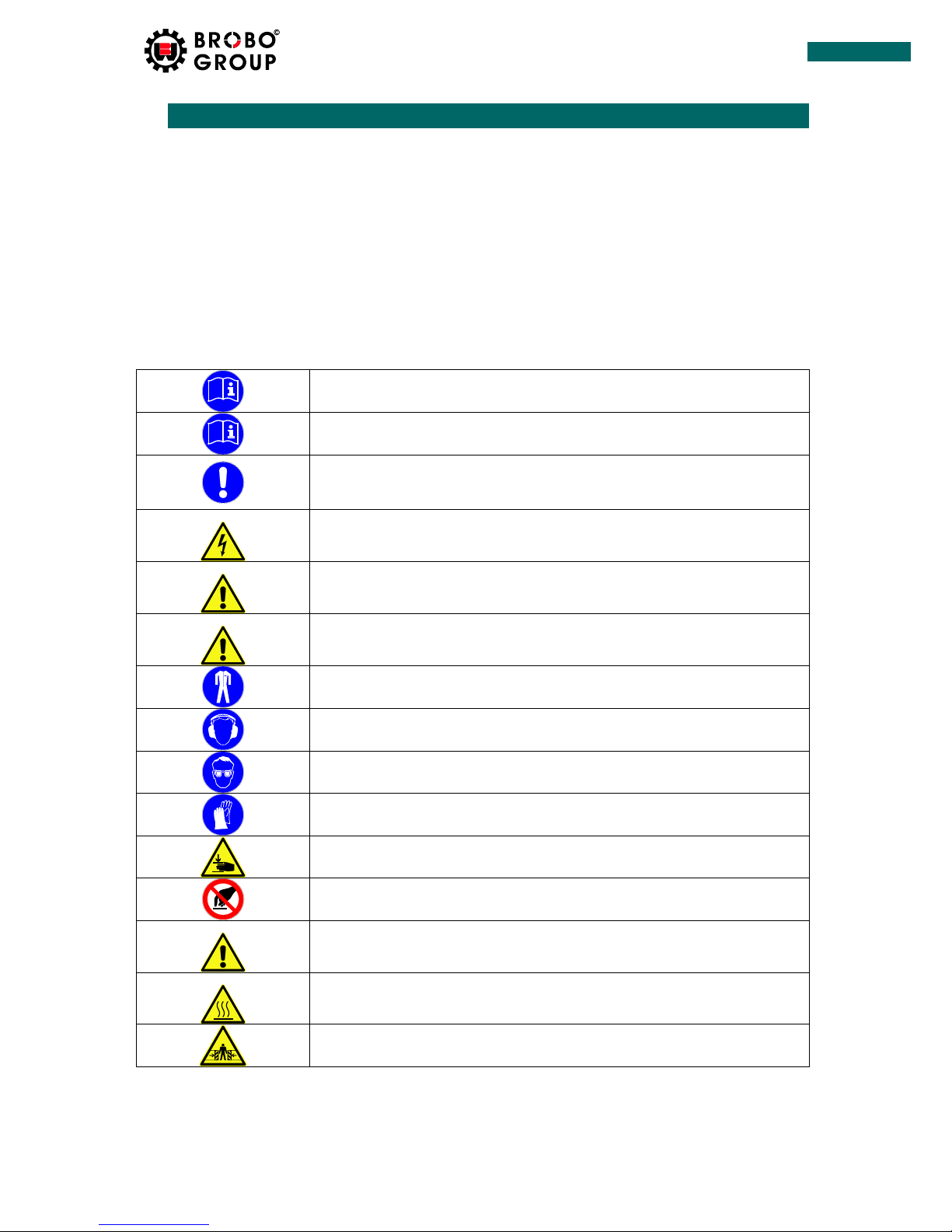
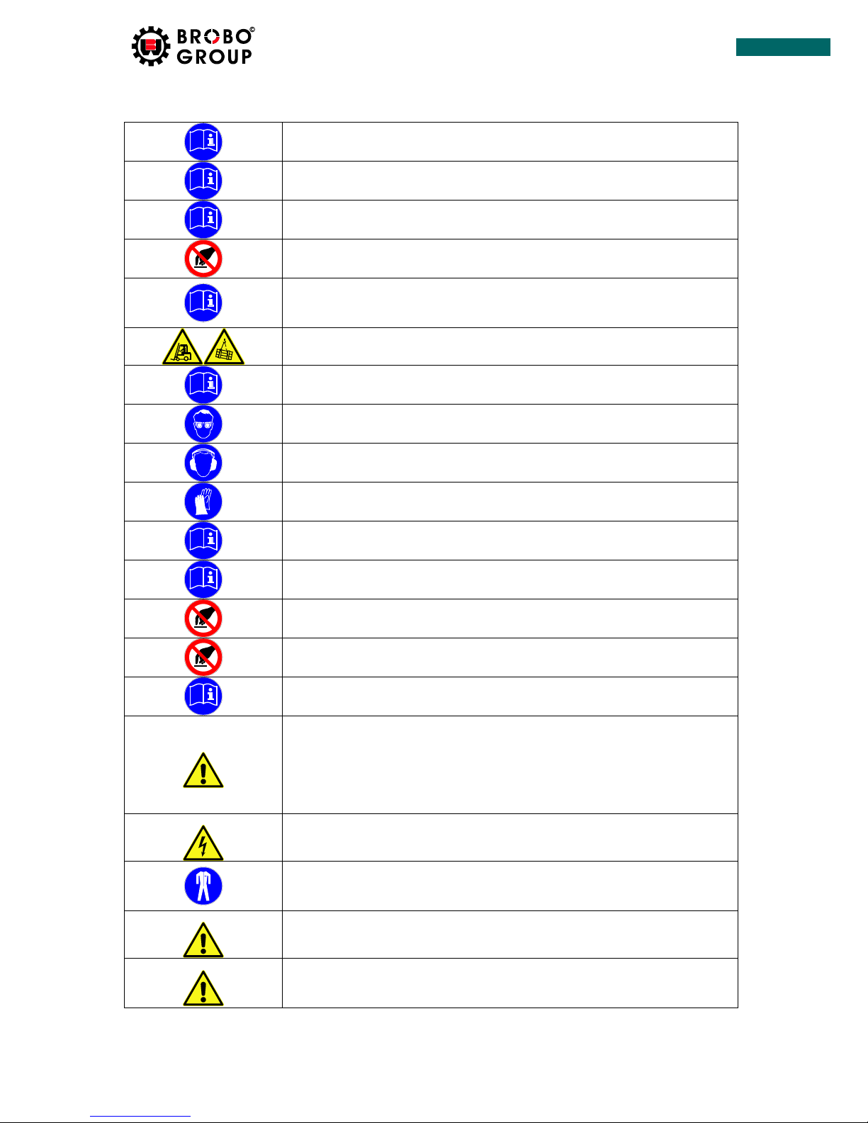
2.1 DESCRIPTION OF THE SYMBOLS USED IN THE INSTRUCTION ................................................. 3
2.2 SAFETY INSTRUCTIONS ............................................................................................................ 4
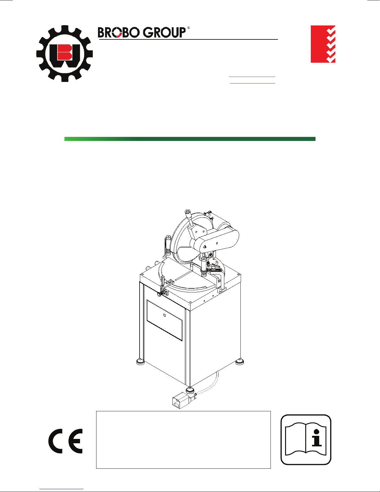
3. PRODUCT DESCRIPTION .................................................................................................................. 6
3.1 GENERAL VIEW ........................................................................................................................ 6
3.2 TECHNICAL DESCRIPTION ........................................................................................................ 7
3.3 TECHNICAL FEATURES ............................................................................................................. 7
3.4 CUTTING DIAGRAMM.............................................................................................................. 7
4. INSTALLATION ................................................................................................................................. 8
4.1 TRANSPORTATION INSTRUCTIONS.......................................................................................... 8
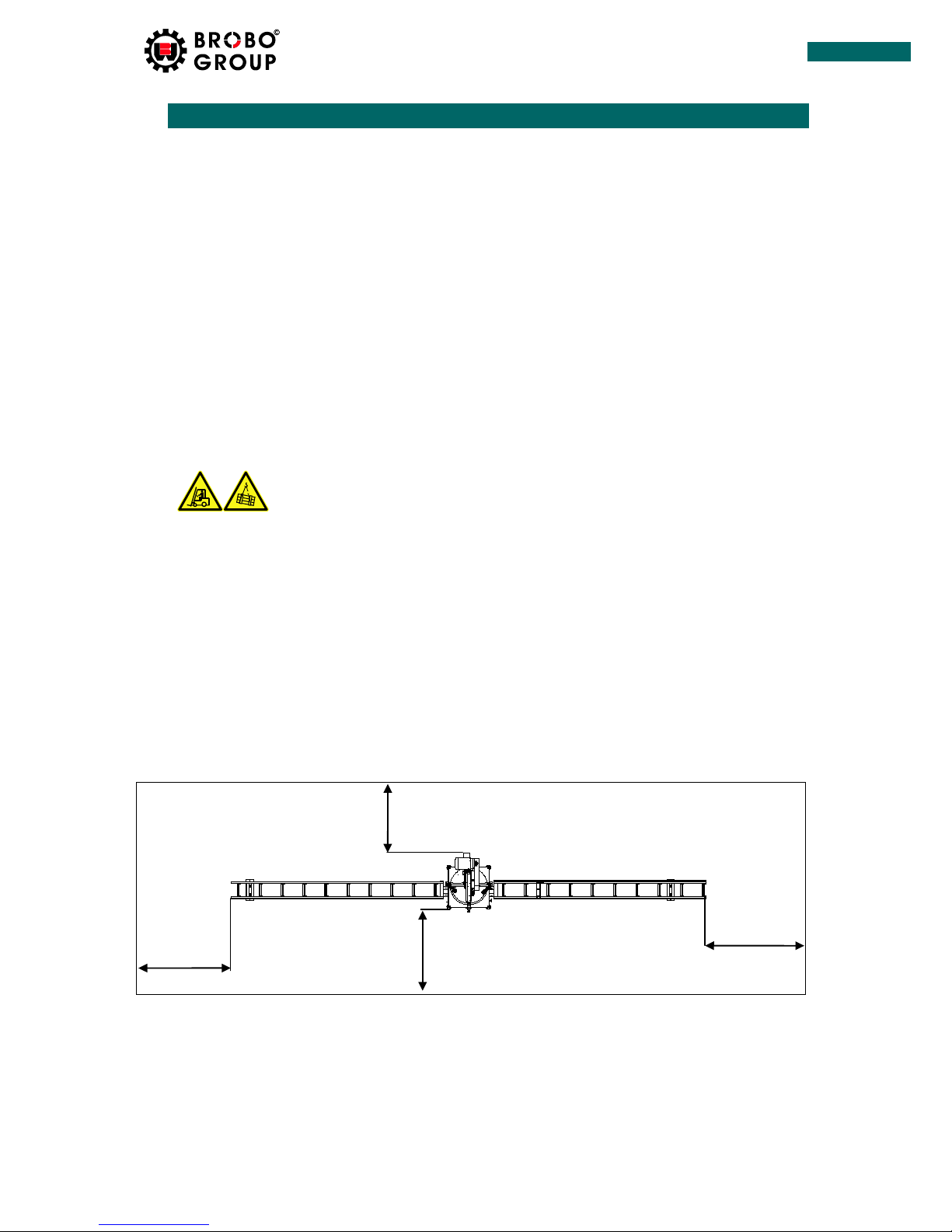
4.2 REQUIRED WORKING AREA ..................................................................................................... 8
4.3 INSTALLATION SETTINGS ......................................................................................................... 9
4.4 FIRST CONNECTION ............................................................................................................... 10
5. PRINCIPLES OF WORK.................................................................................................................... 11
5.1 MAIN SETTINGS ..................................................................................................................... 11
5.1.1 MEASURE CALIBRATION ................................................................................................ 11
5.2 MACHINE CONTROL ELEMENTS ............................................................................................ 11
5.3 OPERATION OF THE MACHINE .............................................................................................. 12
6. MAINTENANCE AND THE LUBRICATION OF THE MACHINE .......................................................... 13
6.1 MAINTENANCE TABLE ........................................................................................................... 13
6.2 MAGNETIC SENSOR ............................................................................................................... 14
6.3 CHANGING THE BLADE .......................................................................................................... 15
7. PNEUMATIC ELEMENTS................................................................................................................. 16
7.1 VALVE AND CYLINDER CONTROL........................................................................................... 16
7.2 COOLING SYSTEM .................................................................................................................. 17
8. TROUBLESHOOTING ...................................................................................................................... 18
8.1 ACTIONS TO BE TAKEN DURING FAILURE.............................................................................. 18
8.2 FAILURE – REASON – SOLUTION TABLE................................................................................. 18
9. CIRCUIT DIAGRAMS ....................................................................................................................... 19
9.1 PNEUMATIC CIRCUIT DIAGRAM ............................................................................................ 19
9.2 ELECTRIC CIRCUIT DIAGRAM ................................................................................................. 20
10. WARRANTY .............................................................................................................................. 22

page. 2/ 23
2
INTRODUCTION
1. INTRODUCTION
We congratulate you on acquisi on of the high-quality equipment. Undoubtedly, you have made a
correct and well-founded choice, produc on of our company is the highly reliable product corresponding to the
European quality standards. The equipment is simple in usage, has high consumer proper es and will serve you
long.
User instruc on contains the manufacturer states principles of work and machine use. Each operator,
beginning to work on the machine should familiaris n vely with the instruc on and understand it.
At correct oper on and observance requests of the present instruc on the manufacturer guarantees
working capacity of the machine during a warranty period.
MANUFACTURER:
Probably that some func onal features of the machine are not reflected in the given document.
Conformity of the informa on containing in the given document is checked by us. Nevertheless
some divergences are possible and complete conformity of the validity is not guaranteed.
The manufacturer reserves the right on produc on and instruc on change.
m
BROBO WALDOWN (AUST) PTY. LTD.
A.C.N. 098 264 316
A.B.N. 42 098 264 316
65-67 Williams Rd, Dandenong, 3175
PO BOX 4274 Dandenong Sth, 3164
Victoria, AUSTRALIA.
Tel: 61 3 9794 8751Email:info@brobo.com.au
Fax:61 3 9794 8792 Website: www.brobo.com.au
Quality
Endorsed
Company
ISO 9001 Lic. 10292
SAI GLOBAL
Quality System

page. 3/ 23
3
SAFETY APPLICATIONS
2. SAFETY APPLICATIONS
1. It is forbidden to use machine to any person, except the operator.
2. Start operation only at complete reliance that you have familiarized and have understood with
designations and the definitions, concerning safety.
3. It is forbidden to work and execute operations on the machine for operator who has not familiarized
with the given instruction,
4. Acquaintance and understanding of the given instruction has importance for prevention of aggrieving
to the operator, third persons, animal, to environment and the machine.
DO NOT MAINTAIN THE MACHINE WITHOUT OBSERVANCE OF THE ABOVE-STATED ITEMS AS SUCH
OPERATION OF THE MACHINE IS UNEQUIVOCALLY DANGEROUS!
2.1 DESCRIPTION OF THE SYMBOLS USED IN THE INSTRUCTION
Instructions on the data given for the purpose of acquaintance with the machine.
Instructions on necessity of familiarity with a management before machine tool
operation.
Instructions on safety conditions which are obligatory for observance by the user
for the purpose of the prevention of drawing of a possible damage to the
machine.
Warning of high voltage presence.
Warning of possible harm to health of the person and of any kinds of time
damage.
Warning of possibility of occurrence of failures with a deadly or traumatic
outcome.
Instructions for work in protective clothes.
Instructions on necessity of use of ear-phones at work on the machine.
Instructions on necessity of use of goggles at work on the machine.
Instructions on necessity of use of gloves at work on the machine tool.
Warning about possible trauma receptions at hands clamping.
Prohibiting sign. It is forbidden to touch. Dangerous.
Warning of performance of necessary measures before the beginning of service
of the equipment.
Warning of heat presence.
Attention! Danger of a clamp!

page. 4/ 23
4
SAFETY APPLICATIONS
2.2 SAFETY INSTRUCTIONS
ATTENTION! Read the instruction and familiarize with all rules and positions.
Keep the instruction in a reliable place. The instruction should be near at hand,
for consultations in an operating time on care of the equipment.
The expert performing works on installation of the machine tool, is obliged to
study the given instruction attentively.
It is forbidden to carry out repair at occurrence of failure of the machine for
operator, failure should be eliminated by the expert of service department.
The machine and its details are necessary for protecting from every possible
external influences. Carry out the regular control of filter-regulator and fill up oil
level at its insufficiency.
It is forbidden to be under the machine during loading and unloading.
It is necessary to provide machine grounding. It is forbidden to maintain the
machine tool without grounding!
At work on the machine it is necessary to use goggles.
Not to be treated to action of natural noise of the machine it is necessary to use
ear-phones.
At replacement of disks it is necessary to use gloves.
It is necessary to use only original spare parts.
Make thrifty use of the control panel, do not suppose any mechanical damages.
Equipment start is carried out by the expert of service department. It is
forbidden to suppose any other person to start.
Equipment repair should be carried out only by experts of the service centre and
only with use of the original spare details and parts.
Use the equipment for other purposes which distinct from are the provided
scope can lead to dangerous situations.
Be always attentive and watch that you do, do not start thoughtlessly work with
the machine. Machine operation is forbidden if you have got tired or be under
the influence of narcotic substances, alcohol or medicines. The minute
carelessness at equipment operation can lead to serious traumas or mutilations.
Operation of the machine with the damaged network cable is forbidden.
It is necessary to immediately replace the damaged cable with the new.
Use special working clothes. Don’t wear spacious subjects of clothes or an
ornament. Preserve hair, clothes and gloves from mobile knots and details. Free
clothes, ornaments or long hair can be tightened by moving parts of machine.
Before the repair or service beginning it is necessary to disconnect a supply of
electricity and compressed air from the machine.
It is forbidden to remove the protective details which are on the machine. It is
necessary to remember that protective details of the equipment are established
for the purpose of safety at work on the machine.

page. 5/ 23
5
SAFETY APPLICATIONS
Avoid clamping hands between the cylinders intended for fixing of a cross-
section and moving parts of the equipment.
Do not open safety covers to a machine blackout.
Only one operator should work on the machine.
The machine should pass regular service and adjustment. Do not use the
machine tool in faulty condition.
Do not use the machine tool in wet and damp premises.
It is forbidden to touch a heating plate of the working machine.
Attention! Do not stay between moving cutting heads.

page. 6/ 23
6
PRODUCT DESCRIPTION
3. PRODUCT DESCRIPTION
3.1 GENERAL VIEW
Picture 3.1-1 General view
1. Power switch
2. Motor “START” buton
3. Clamping pedal
4. Electric panel
5. Clamping cylinder
6. Angle fixator
7. Cutting degree adjustment handle
8. Cutting table
9. Cutting head
10. Protective cover
11. Motor
12. Cooling system switch
13. Coolant sprey speed regulator
14. Conveyor connection
15. Left conveyor
16. Right conveyor
17. Size adjustment stop
2
9
4
6
8
11
1
3
5
7
10
12
13
14
17
16
15
3

page. 7/ 23
7
PRODUCT DESCRIPTION
3.2 TECHNICAL DESCRIPTION
-Cutting range +45° / -45°
-Special design of sliding plate prevents sawdust collecting inside it
-Diameter of a saw blade is 400 mm
-Smooth movement of cutting head is carried out with the shock-absorber
-Vertical pneumatic clamping kit
3.3 TECHNICAL FEATURES
3PH 380V model
Voltage : 380 V 220V
3PH 220V model
Frequency : 50/60 Hz 50/60 Hz
Motor power : 1,1 kW 1,1 kW
RPM : 2810 2810
Total power : 1,1 kW 1,5kW
Air pressure : 6–8 Bar 6-8 Bar
Air consumption : 2,2 lt./min. 2,2 lt./min.
Sawblade external Ø diameter : 400 mm 400 mm
Sawblade internal Ø diameter : 32 mm 32 mm
Sawblade thickness : 4 mm 4 mm
Sawblade Z : 120 120
Sawblade RPM : 4800 4800
Minimum cutting length : 360 mm 360 mm
Maximum cutting length : 3300 mm 3300 mm
Width : 780 mm 780 mm
Length : 6570 mm 6570 mm
Height : 1570 mm 1570 mm
Weight : 140 kg 140 kg
3.4 CUTTING DIAGRAMM
Ø400 mm
X (mm)
Y(mm)
050 150 200
0
50
100
150
200 45°
90°

page. 8/ 23
8
INSTALLATION
4. INSTALLATION
►The equipment has passed working tests of all mechanic, electric and pneumatic units at factory.
All materials and the spare parts have passed the complete careful control before delivery in a
transport company.
►At equipment acceptance make the control on availability/absence of any transport damages.
4.1 TRANSPORTATION INSTRUCTIONS
►The machine should be standing upright and positioned centrally on top of a wooden pallet.
While the machine is situated on the pallet, position the forklift arms under the pallet between
the runners, keeping in mind that the machine is head heavy. Move the entire unit to an
accessible area as close as possible to the final location.
►Carefully remove the packing frame surrounding the saw unit. Once completed, proceed by
elevating the machine away from the pallet base using a sling harness wrapped around the
cutting head of the saw. Ensure that the floor is as level as possible before finally positioning the
machine to the desired location.
It is forbidden to be under the machine during loading and unloading.
1. At loading to forklift it is necessary to avoid damage of cables, cylinders, hoses, filter-
regulator and control panels.
2. Means for moving should have dimensions corresponding for the machine.
3. Avoid blows of the machine tool in the course of moving.
4. Machine moving should be performed by a forklift.
4.2 REQUIRED WORKING AREA
►For high-efficiency work of the machine it is recommended to place the machine in workshop
with maintenance of indicators of the distances indicated by the manufacturer. A – B the placings
shown on the plan, it is necessary to keep plots the free. The minimum recommended distance
from the uppermost point of the machine tool to a ceiling constitutes 2 mt.
Picture 4.2-1 Required Working Area
500 mm
А100 mm
B

page. 9/ 23
9
INSTALLATION
4.3 INSTALLATION SETTINGS
►Care should be taken for the floor to be straight and sound the
machine will be positioned. Note that there will be sufficient distance
around the machine in order to work safely, for easy servicing and
maneuvers.
►
The machine should be scaled. The machine that is well scaled will
reduce the vibration, working will be easier and the production and the
quality will also increase.
►Pressure of air should constitute 6-8 Bar. Usage of a thick hose
interferes with air pressure decrease on all length of a line. Besides, it is
necessary to avoid hit of moisture for the prevention of breakage of
valves and pneumocylinders.
►Warning:if there is no air dryer in the pneumatic system connection
of machine, parts of the pneumatic group are not subject to warranty
service!
►The electrical connections of the machine should be done by the
service staff or qualified electrician.
►
The used electric switchboard should correspond to norms of safety
and electric standards. The voltage stabilizer should be connected to a
line of a supply of electricity.
►The grounding contour prevents aggrieving to the user by wandering
currents, for this reason the correct system and reliability of a contour of
grounding has special importance.
►Grounding line should be connected to the machine body.
►Voltage changes, its increase and decrease is harmful and dangerous
to the equipment. To prevent these events use a voltage stabilizer.
Otherwise the manufacturer does not bear any responsibility for possible
malfunctions.
►Warning: if there is no voltage stabilizer in electric system connection
of the machine, parts of electric and pneumatic are not subject to
warranty service!
►In the machine used a cable with 5 pins (3 phases + 1 neutral + 1
grounding), corresponding to IP 44 standards and the power of machine.
It is necessary to ensure that similar standards for plug sockets.

page. 10 / 23
10
INSTALLATION
4.4 FIRST CONNECTION
1. Remove the package.
2. Locate machine on an even horizotal place.
3. Connect electricity (380 V). For 220V working models connect 220V.
4. Checks the sequence of phases (3 phases + 1 neutral + 1 grounding).
5. Connect air pressure (6-8 bar).
6. Check oil level in filter-regulator.
►The first connection should be made by service team. The manufacturer does not bear
responsibility for damages incurred by connection the machine by not service team.
First connection by service team:
•Eliminate failures occured during transportation.
•Check the uniformity of machine installation.
•Check the electrical and air connections.
•Switch on the machine
•Instruct the operator of the machine
•Give instruction on the safety and maintenance of machine
Note: If in new connection machine does not work, then the cause could be the
inconsistency of phases in the electrical network, so that motors does not rotate in the
opposite direction, the machine is protected by a special control-phase relay. Changes of phases in
the connection socket should be performed by service or qualified electrician.

page. 11 / 23
11
PRINCIPLES OF WORK
5. PRINCIPLES OF WORK
5.1 MAIN SETTINGS
►All necessary factory options are performed on the equipment. At wear of mechanical units or
details, at change of profile system it is necessary to change some options. Necessary options are
given below.
5.1.1 MEASURE CALIBRATION
►Measure the profile after cutting. Set the dimension you get on the ruler (1) by the pointer (2),
weakening its attachment.
Picture 5.1-1Measure calibration
5.2 MACHINE CONTROL ELEMENTS
Picture 5.2-1 Machine control elements
1. Power switch
2. Motor “Start” button
3. Clamping pedal
4. Cutting degree adjustment
1
2
1
3
2
4

page. 12 / 23
12
PRINCIPLES OF WORK
5.3 OPERATION OF THE MACHINE
The below prerequisites should be ready in order for the machine to be ready to operate.
Power switch ON
Front protection cover closed.
Profile clamping pistons back
Note: During the initial operation, check the rotation of the saw.
Before the operation starts it is necessary to be convinced of absence people (service staff,
etc.) near to the machine which can receive damages at movement of units of the machine;
the operator should be attentive for the purpose of protection of health of persons which
can be near to it, also it is necessary to warn surround persons about machine operation.
When the machine is ready to operate, the below actions are taken:
1. The profile is placed to the table horizontally.
2. If you want to cut in a different angle, you can adjust the angle by pulling up the angle fixing
handle (4)
3. By stepping the profile pressing pedal (3) clamps come down and press the profile.
4. Press the saw start button, the blade head is set down by pulling down the handle.
5. While the blade is cutting, the protection cover opens automatically.
6. When we pull up the handle which pulls down the saw, protection cover closes
automatically.
7. Push the pedal (3) again, and the profile squeezing pistons rises, let the profile free.
8. The cutting work is completed.

page. 13 / 23
13
MAINTENANCE AND THE LUBRICATION OF THE MACHINE
6. MAINTENANCE AND THE LUBRICATION OF THE MACHINE
1. All air and electrical energy should be disconnected before maintenance.
2. In order to disconnect the electric energy, set the power switch ‘’OFF’’ position.
3. In order to disconnect the air completely, separate the air input hose from the machine.
4. Perform the cleaning of the machine every day. Clean the daily sawdust. The cleaning can be
performed with an air gun.
5. Use only the lubrication products recommended by our factory.
6. Electrical and pneumatic panels should be cleaned once a month with air against the dust
and sawdust.
7. The dismantling and assembling process of the motor cutter ends should be performed by an
expert.
8. If the clamping cylinders do not press the profile, the pressure should be checked from the
air lubricator.
9. The machine needs at least 6 bar air pressure. Pressure should be followed.
Daily maintenance
►Clean machine and surround area with compressed area.
►Clean with duster oil, shaves, dust etc.
►Check bladesaw. Must be changed if blunt or saw damage occurs. See page 15 CHANGING THE
BLADE
Weekly maintenance
►Check daily maintenance
Monthly maintenance
►Check weekly maintenance
6.1 MAINTENANCE TABLE
Daily Weekly Monthly
Clean machine and
area from dust, oil etc. X
Check the sawblade X

page. 14 / 23
14
MAINTENANCE AND THE LUBRICATION OF THE MACHINE
6.2 MAGNETIC SENSOR
►There is a magnet inside the pneumatic cylinder and this magnet moves with the piston.
►The magnetic sensor connected to the surface of the piston open its contacts when it is effects
by this magnet. If the position of the magnetic sensor changes that is to say it will not contact
with the magnet so the signal will not go the PLC and therefore there will not be any action
performed.
In this case the sensor is placed by moving forward or backward slightly in the arrow direction.
(the light on the sensor turns on when the magnet contacts with the sensor and the sensor is
fixed in that position so the problem will be solved).
Picture 6.1-1 Sensor adjustment
1. Sensor
2. Piston and magnet
1
2

page. 15 / 23
15
MAINTENANCE AND THE LUBRICATION OF THE MACHINE
6.3 CHANGING THE BLADE
1. All air and electrical connections should be disconnected.
2. Protective covers must be removed.
3. The nuts on the motor spindle where the saw is installed are must be removed from the saw
place by opening in the opposite direction to each others.
4. After the saw is replaced with the new one, the same procedure is reversed.
5. After the saw is replaced the covers are replaced too.
Wear gloves during the saw replacement.
Picture 6.2-1 Blade changing

page. 16 / 23
16
PNEUMATIC ELEMENTS
7. PNEUMATIC ELEMENTS
7.1 VALVE AND CYLINDER CONTROL
Picture 7.1-1 Valve and cylinder control
1. Piston cuff
2. Ring gasket
►If some operations on machine does not start to process or an air leakage occurs continuously in
the valves, you should perform following:
1. Look the pneumatic drawing to understand which cylinder works with which valve. If you
don’t have the pneumatic drawing, follow the input- output pipes of the cylinder to
understand.
2. Take off the air pipes connected to the A and B cable glands. Give air from A and check from
B. If air comes from B, the cylinder seal must be malfunctioning.
3. When air is given from B, the cylinder rod must still be giving out air, the neck seal C must be
malfunctioning. If after checking them, A, B and C give out no air but there still is a leakage
through the valves exhaust, check the valve.
4. After you have checked them, if A, B and C give out no air but there still is a leakage through
the valves exhaust, then check the valve.
5. If the coil does not move by pressing the manual button, the coil may have broken down and
it must be replaced. (A very low voice coming from coils when electric applied to them must
be heard.) If the voice cannot be heard, check the electricity feed for coils.
1 2

page. 17 / 23
17
PNEUMATIC ELEMENTS
7.2 COOLING SYSTEM
(op on for aluminium profiles cu ng)
Picture 7.4-1 Cooling system
1. Switch ON / OFF for cooling system
2. Coolant Spray speed regulator
3. Coolant tank (inside view)
Cu ng fluids are various fluids that are used in machining to cool and lubricate
the cu ng tool.
Before PVC profiles cu ng opera on started switch OFF the cooling system. Open the
protec ve covers of cu ng heads and clean the inside area from coolant.
Cu ng fluid recommended to use:
«Brobolube (Part Number: 9601480)
1
3
2

page. 18 / 23
18
TROUBLESHOOTING
8. TROUBLESHOOTING
8.1 ACTIONS TO BE TAKEN DURING FAILURE
1. Check the machine feeding voltage working with 3 phase of get it checked.
2. There should be 6 atmospheric pressured air. You can read this value over the regulator-
filter manometer of the machine.
3. Open the valve board cover of the machine. Check whether there is air leakage or not in air
hoses, air connection elements or valves. Try to correct it if there is an air leakage.
4. Close the main power switch on the machine and open the cover of the electrical board.
Check whether the two fuses in the board have blown or not. Correct if there is a break in
the cables on the contactors and if there is looseness in the connector screws.
8.2 FAILURE – REASON – SOLUTION TABLE
FAILURE
REASON
SOLUTION TABLE
There is no movement Electrical failure
Air connection failure
Check the safety power switch.
Check the fuses.
Check the input phases.
Check the air connections.
Motor does not work Thermic blown
Motor failure
Check the thermic of the left
head.
Replace the motor with the
new one.
Clamping cylinders do not
clamp
Valve or cylinder failure
Pedal contact failure
See page 16 VALVE AND
CYLINDER CONTROL
Check the pedal contact
The system is leaking air
Air connection, joint places and
union failure
Check the connection and joint
places
Right saw is not moving
forward
Valve and piston failure
Control device has not reached
the position
See page 16 VALVE AND
CYLINDER CONTROL
Check the positioning device
indicators
The sawdust going out the saw
is yellow and there is an odor
like the pvc burnt.
Saws are blunt or the teeth are
broken
Sharpen the saw or replace
with the new one.
See page 15 CHANGING THE
BLADE

page. 19 / 23
19
CIRCUIT DIAGRAMS
9. CIRCUIT DIAGRAMS
9.1 PNEUMATIC CIRCUIT DIAGRAM
CONTROL:
DRAWING BY:
DRAWING :
07.03.2009
DATE
MANUAL CUTTING SAW
TNF - 115
PNEUMATIC DIAGRAM
REV:
PAGE: 1
AIR GUN
8 BAR
ONEWAY STREAM
CONTROL VALVE
5/2 24 DC
PEDAL VALVE
CLAMPING
CYLINDERS
This manual suits for next models
1
Table of contents
Other Brobo Saw manuals

Brobo
Brobo S315G User manual

Brobo
Brobo SA350H User manual

Brobo
Brobo TNF 115 2 Series User manual

Brobo
Brobo OHS Series User manual

Brobo
Brobo VS400D User manual

Brobo
Brobo S315D, S350D, S400B User manual

Brobo
Brobo S350D User manual

Brobo
Brobo FA 3000K User manual

Brobo
Brobo VS315D User manual

Brobo
Brobo VS350D User manual