OPERATING MANUAL FOR BROBO GROUP
MANUAL METAL CUTTING SAWS
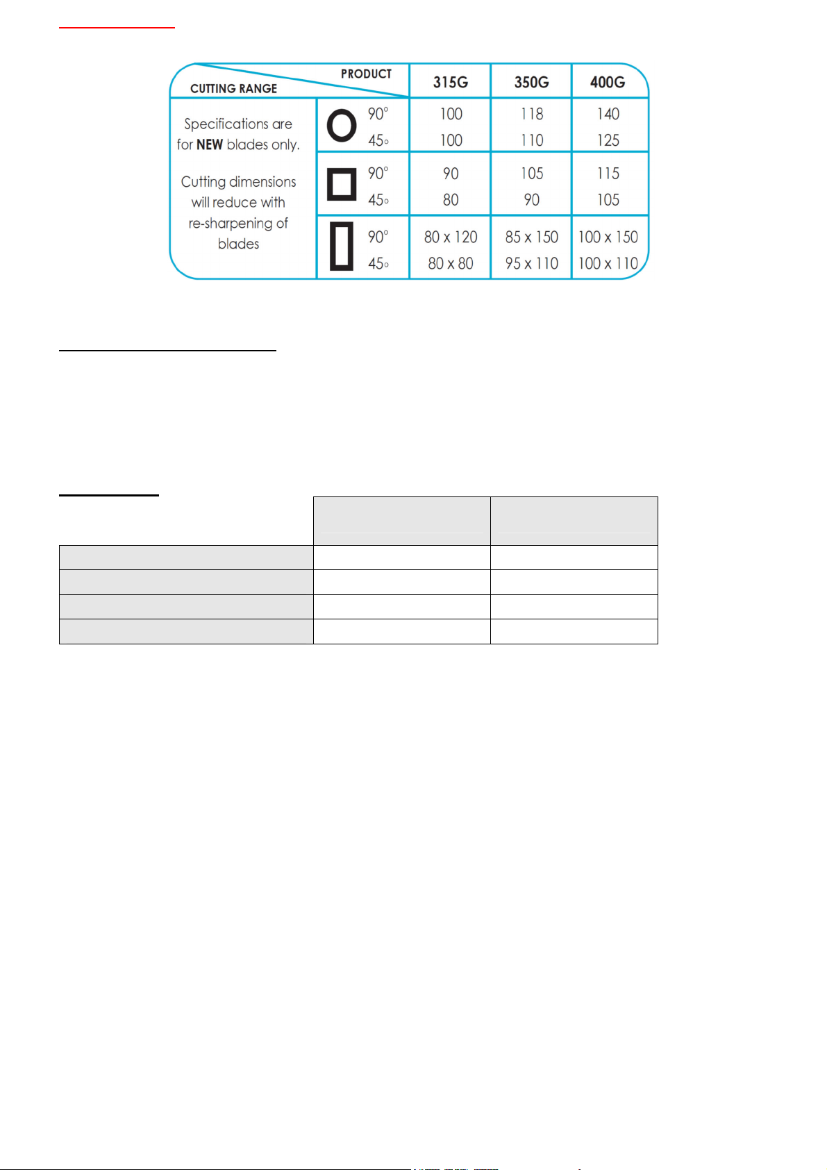
TECHNICAL SPECIFICATION
CHAPTER 1: Installation of the Machine
1.1 Unpacking & Handling the Machine
1.2 Parts Checklist
1.3 Minimum Requirements
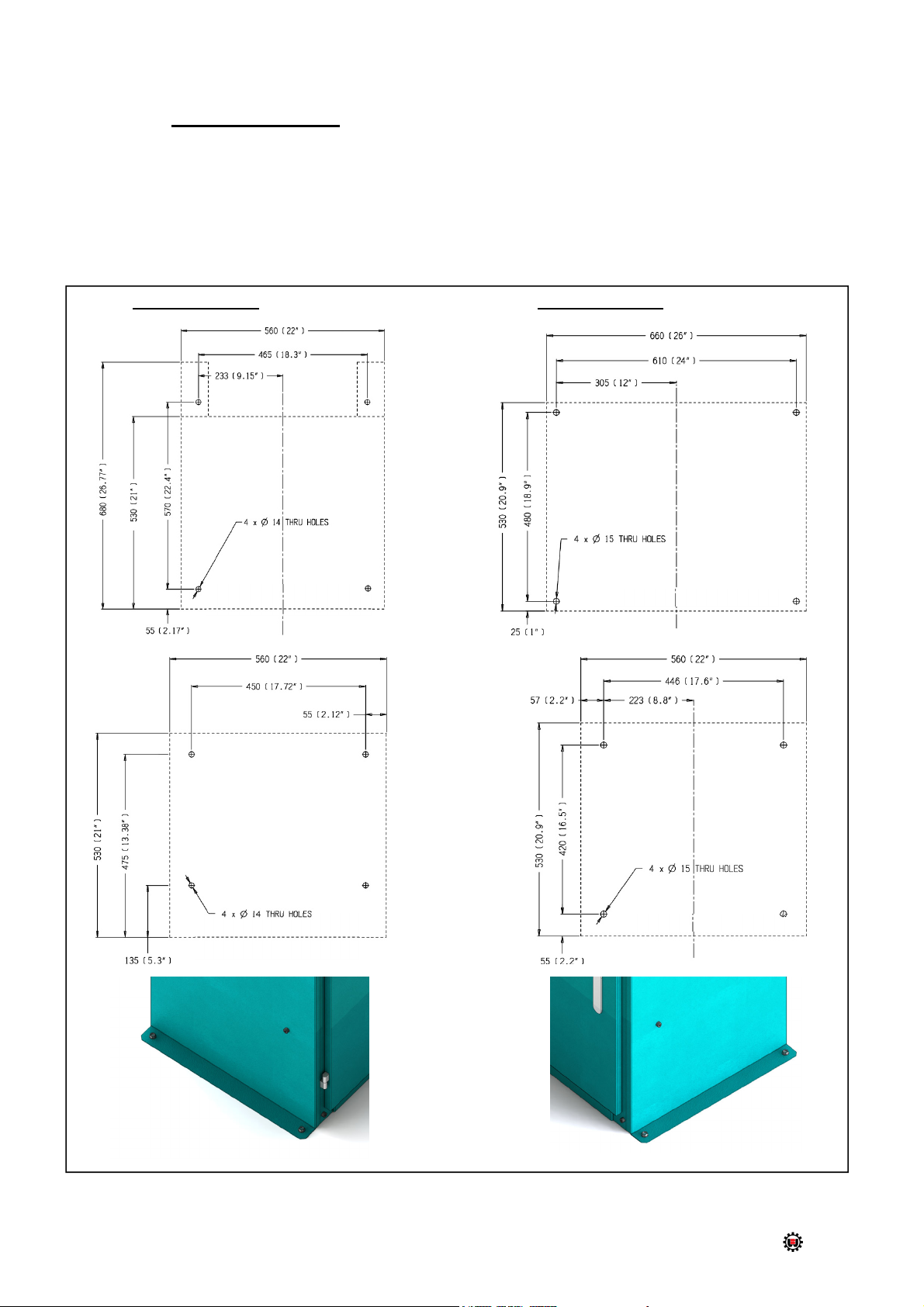
1.4 Anchoring the Saw
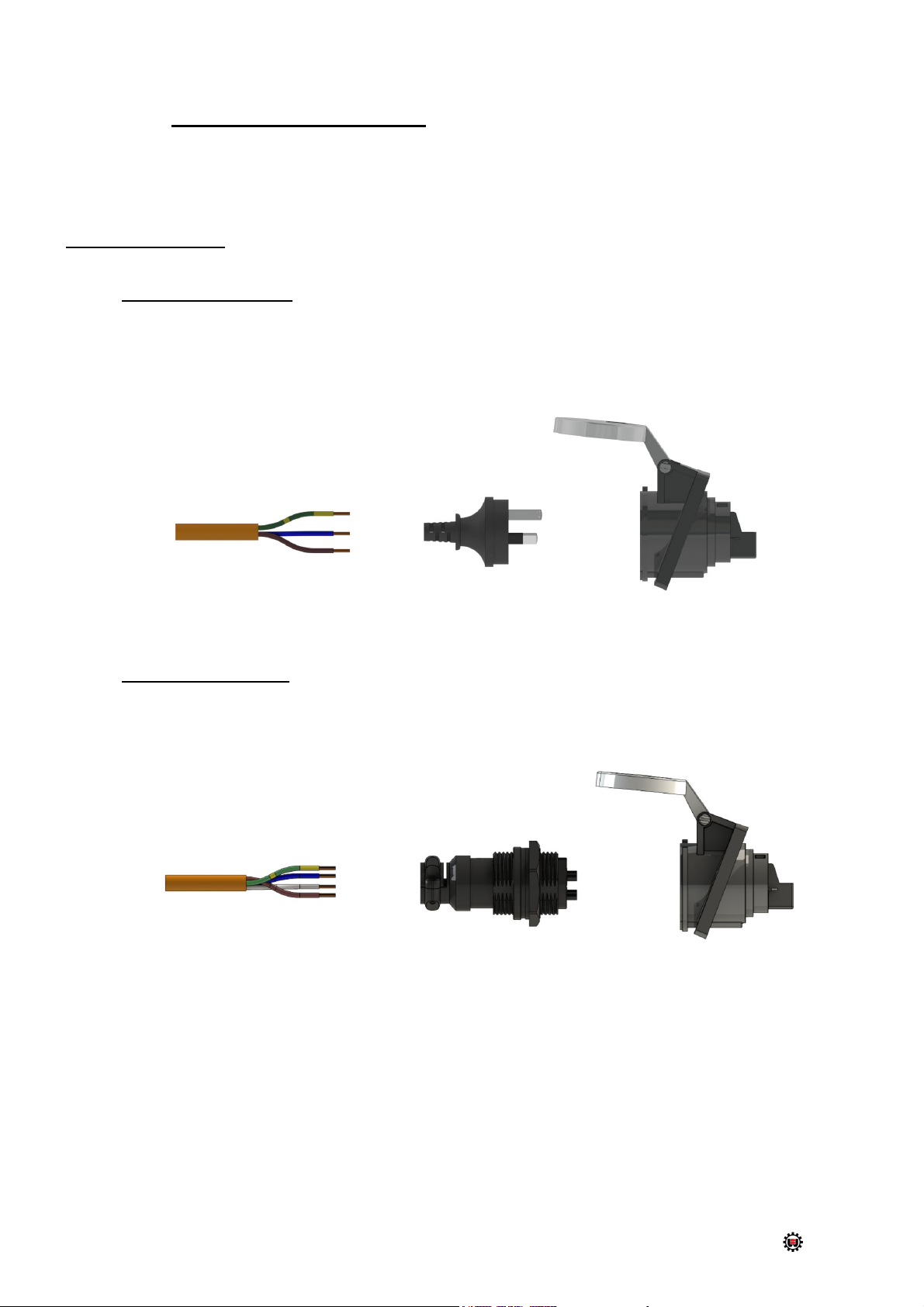
1.5 Connection to Power Source
CHAPTER 2: Safety & Accident Prevention
2.1 General Requirements
2.1.1. Noise Level
2.1.2. Power Supply
2.2 General Requirements
2.3 Advice for the Operator
2.4 Machine Safety Devices
2.4.1. Reference Standards
CHAPTER 3: Main Functions & Operation of the Machine
3.1.1. Cutting Head
3.1.2. Saw Safety Guard
3.1.3. Saw Handle (with ‘Dead Man’ Trigger Switch)
3.1.4. Main power standby & Speed selector switch
3.1.5. Manual Vice Clamp
3.2 Preparation for Operation
3.3 Operation Recommendations
CHAPTER 4: Drawings, Layouts, Assembly & Spare Parts
4.1 Main Dimensions
4.2 Cold Saw Assembly
4.3 Standard Gearbox Assembly
4.4 S400 Gearbox Assembly
4.5 Coolant Tank Assembly
4.6 Backfence Assembly
4.7 Deadman Trigger Assembly
4.8 Standard Manual Vice Assembly
4.9 Dual Manual Vice Assembly
4.10 Broborule Series
4.11 Electrical Schematic Drawings
CHAPTER 5: Adjustments for the Saw Unit
5.1 Changing the Blade
5.2 Adjusting the Cutting Angle
5.3 Cutting & Feeding Speeds
5.4 Refilling the Lubricator
5.5 Adjusting the Brobolube Unit
5.5.1 Lubricating Oil Precautions – Health Hazard Information
CHAPTER 6: Maintenance and Selection of Consumables
6.1 Role of the Operator
6.2 Maintenance Requirements
6.3 General Maintenance of Functioning Components
CHAPTER 7: Troubleshoot
7.1 Troubleshooting For Blade & Cutting Problems
7.2 General Troubleshooting
APPENDIX
i. Hazard/Risk Assessment
ii. Workplace Health & Safety Policy