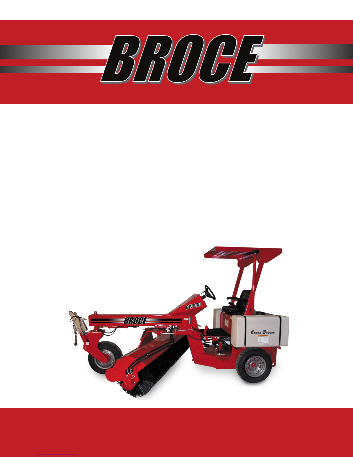
Broce BW-260 User manual

1
MODEL BW-260
For parts and service, call:
(866) 283-2759
Waldon Equipment, LLC, 201 W. Oklahoma Ave., Fairview, OK 73737
OPERATIONS
MANUAL
For parts and service
(866) 283-2759

2
MODEL BW-260
For parts and service, call:
(866) 283-2759
Waldon Equipment, LLC, 201 W. Oklahoma Ave., Fairview, OK 73737
TABLE OF CONTENTS
DESCRIPTION
WARRANTY
SPECIFICATIONS
START UP & PROPELLING
TOWING PROCEDURES
OPERATION OF THE SWEEPING CORE
SWEEPING TIPS
EXTENDING BRUSH LIFE
MACHINE OPERATION & SAFETY
OPERATION & SAFETY DECALS
OPERATORS PLATFORM
OPERATION CONTROLS
FUEL AND HYDRAULIC FILL LOCATIONS
TOWING HITCH & HOOD LATCH LOCATIONS
MACHINE SERVICE & SAFETY GUIDELINES
LUBRICATION & MAINTENANCE
BRAKE INSPECTION & SERVICE
ENGINE
STORAGE
BROOM WAFERS
PAGE #
3-4
5
6-7
8
9
10
11
13
14
15
15
16
17
18
19
20
21
21
22

3
MODEL BW-260
For parts and service, call:
(866) 283-2759
Waldon Equipment, LLC, 201 W. Oklahoma Ave., Fairview, OK 73737
LIMITED TWELVE (12) MONTH WARRANTY
For a period of twelve (12) months or 1,000 hours whichever comes rst, from the date of delivery of
product to the original user, Waldon Equipment, LLC, of Fairview, Oklahoma warrants each product
to be free from manufacturing defects, subject to the limitations contained in this policy. This limited
warranty covers parts and labor.
This warranty does not apply to defect caused, in whole or in part, by unreasonable use while in the
possession of the user, including, but not limited to, failure to properly set up product, failure to pro-
vide reasonable and necessary maintenance, normal wear, routine tune ups of adjustments, improp-
er handling, accidents, operation at speed of load conditions contrary to published specications,
improper of insufcient lubrication, or improper storage. This warranty is not a guarantee that the
performance of each product will meet the expectations of the purchaser.
Waldon Equipment, LLC, shall not be liable for consequential damage of any kind, including, but
not limited to: consequential labor costs of transportation charges in connection with the replace-
ment of repair of defective parts, lost time or expense which may have accrued because of said
defects. In no event shall Waldon Equipment LLC be liable for any compensatory of consequential
damage. In no event shall Waldon Equipment, LLC’s total liability hereunder exceed the product
purchase price.
Many components used by Waldon Equipment, LLC, are subject to the warranties of their respec-
tive manufacturers. These warranties will be considered void if the product is modied or repaired in
any way not expressly authorized, or if closed components are disassembled prior to return. Closed
components include, but not limited to gearboxes, hydraulic pumps, motors, cylinders and actua-
tors.
Our obligation under the warranty is expressly limited, at our option, to the replacement or repair
at Waldon Equipment, LLC, of Fairview, OK or at a service facility designated by us. We are not
responsible for unauthorized repairs of replacements. Any implied of statutory warranties, including
any warranty of merchantability or tness for a particular purpose, are expressly limited to duration
of this written warranty. We make no other express warranty. This warranty cannot be extended,
broadened, or changed except in writing by an authorized ofcer of Waldon Equipment, LLC.

4
MODEL BW-260
For parts and service, call:
(866) 283-2759
Waldon Equipment, LLC, 201 W. Oklahoma Ave., Fairview, OK 73737
WARRANTY REGISTRATION
Purchased from (Dealership)
Company:
Address:
City:
Deliver Date to Dealer:
Model Number:
Company:
Address:
City:
Delivery Date to Owner:
Purchaser
Purchaser - Type of Business
Construction/Highway
Equipment Dealer
Rental
Municipality
Asphalt Contractor
Other
1. The Purchaser has been instructed and/or has read the manual and understands proper preven-
tive maintenance, operation and safety precautions.
2. The Warranty and Limitations of Liability are found in the Warranty pages enclosed in the Parts
and Operators Manuals.
3. Waldon Equipment, LLC, reserves the right to make design changes or modications to Waldon
products at any time without incurring any obligation to make similar changes of modications
to previously sold units.
4. If this Document is not signed and returned to Waldon Equipment, LLC, the warranty begins at
the date of delivery to the Dealership.
I hereby acknowledge acceptance of above and conditions in the Warranty Policy.
Purchaser/Owner:
Dealer Representative:
Unit Hours:
Serial Number:
State: Zip:
State: Zip:
Unit Hours:

5
MODEL BW-260
For parts and service, call:
(866) 283-2759
Waldon Equipment, LLC, 201 W. Oklahoma Ave., Fairview, OK 73737
SPECIFICATION SHEET
Engine Horsepower
Machine Weight
Machine Weight w/ Water System
Brush Diameters
Broom Length
Broom Drive
Broom Angle
Steering
Fuel Capacity
Hydraulic Oil Capacity
Speed
Inside Sweeping Radius
Water System
24 H.P.
3.100 LB
3.700 LB
6 3/8 “ ID X 24” OD
Full 8 FT
Hydraulic Motor
Full 40 deg (both ways)
60 deg (both ways)
11 GAL
11 GAL
10 mph
5 FT
72 GAL

6
MODEL BW-260
For parts and service, call:
(866) 283-2759
Waldon Equipment, LLC, 201 W. Oklahoma Ave., Fairview, OK 73737
START UP & PROPELLING
CAUTION
Persons should ride in the seat properly wearing their seat belt whenever the vehicle is moving
or in the vicinity of other moving vehicles. Otherwise, they are much more likely to suffer seri-
ous bodily injury in the event of sudden braking or a collision.
When using the seat belts, observe the following:
• Be careful not to damage the belt webbing or hardware. Take care that they do not get
caught or pinched in the seat.
• Inspect the belt system periodically. Check for cuts, fraying, and loose parts. Damaged parts
should be replaced. Do not disassemble or modify the system.
• Replace entire belt assembly (including bolts) if it has been used in a severe impact.
• Replace belt assembly after 3 years of use and 5 years of manufacture.
This model of broom is hydrostatically driven. Motion is achieved by depressing the foot pedal on
the oor board to the right of center. Letting the foot pedal up will result in a braking action caused
by the hydraulic system. This is the proper method for braking on this machine. The brake pedal
on the left side of the oor board should not have to be used except in cases where the engine has
died or there is a problem with the hydraulic system. To maintain operability, occasional use of brake
system is advised to prevent rusting and seizure of components in place.
WARNING
BEFORE STARTING ENGINE, BE SURE PARKING BRAKE IS SET, LEFT FOOT IS ON THE BRAKE
PEDAL AND RIGHT FOOT DOES NOT CONTACT THE CONTROL PEDAL. FAILURE TO DO SO
COULD CAUSE UNINTENDED MOVEMENT OF VEHICLE RESULTING IN INJURY OR DEATH.

7
MODEL BW-260
For parts and service, call:
(866) 283-2759
Waldon Equipment, LLC, 201 W. Oklahoma Ave., Fairview, OK 73737
START UP & PROPELLING
1. Turn the key switch to the start position, all the way to the right. Add fuel is necessary using the
hand operated locking throttle. Release the key switch when the engine starts. Do not use ether
(STARTING FLUID) in this engine, severe engine damage will occur.
2. Use the foot pedal on the oor board to choose the direction of forward or reverse.
3. After the desired direction has been selected, raise engine R.P.M. to about half throttle. Release
parking break. Slowly depress control pedal and adjust the engine to the desired travel speed.
Speed can also be varied by the distance the control pedal is depressed.
4. To stop the engine, turn the key back to the center position. The parking brake must be set
prior to leaving the operator’s seat.
NOTICE
DO NOT REVERSE THE DIRECTION OF TRAVEL WHILE THE BROOM IS IN MOTION. THIS
WILL DAMAGE THE DRIVE COMPONENTS AND VOID THE WARRANTY. THIS TYPE OF OPER-
ATION IS CONSIDERED ABUSE.

8
MODEL BW-260
For parts and service, call:
(866) 283-2759
Waldon Equipment, LLC, 201 W. Oklahoma Ave., Fairview, OK 73737
TOWING PROCEDURES
1. Before towing this machine check the following:
a. The tires should be inated to 32 PSI and be in good condition.
b. Any loose items on the machine should be removed or secured.
c. Check to see that all the lug nuts/bolts are tight on the wheels and that the wheel are in
good condition.
2. The parking brake must always be set before starting to hook up the machine to a towing ve-
hicle. The parking brake must also be set before starting to unhook the machine from a towing
vehicle.
3. Flip switch for Hitch on dash.
4. Drive the broom behind the vehicle. Leave about 5’ between vehicle and broom
5. Lower hitch on to the ball. Have one person guide you if possible.
6. When hitch is on, power down with control valve where the tire is about 6” off the ground.
7. Put the shaft pin in the hole to secure.
8. Unlock hubs on the rear wheels of the machine so that it will roll freely without turning the hy-
draulic motors.
9. Open ¼” ball valve on hitch for brakes.
10. Hook up the lights and make sure they are in good working order.
11. Hook up tow chain.
12. Reverse procedure for unhooking.
13. Release the parking brake. Pull the machine a short distance and make sure the machines
brakes are not dragging. If they are, adjust and/or repair them so that they will work effectively
when needed.
Note: When the machine is to be unhooked from the towing vehicle, set the parking brake and pro-
ceed to unhook the machine in the same manner as it was hooked up, except in reverse order.
Note: The speed at which this machine is towed depends on conditions and the personal judgment
of the individual in charge but must not exeed 45 mph. Broce Manufacturing Co. will not be re-
sponsible for neglect or poor judgment at any time during machine operation and/or towing of the
machine.

9
MODEL BW-260
For parts and service, call:
(866) 283-2759
Waldon Equipment, LLC, 201 W. Oklahoma Ave., Fairview, OK 73737
OPERATION OF THE SWEEPING CORE
All broom functions are hydraulically operated. The control levers are located on the dash on the
right and left side of the steering wheel. The joystick located on the right side of dash controls the
core height up down and the right and left angle of Broom. The handle on the left
turns on and off broom rotation.
RAISE / LOWER / FLOAT DETENT
To raise the core, move the joystick to the back, “Raise,” position until the core is raised all the way.
The handle will return to the hold position and core height will be maintained. To lower the core
during normal sweeping conditions, move the joystick to the front, “Float position. The
“Float” position will allow the core to maintain the ideal contact while allowing it to oat over bumps
or contours in the surface. To adjust the core height downward, slowly move the handle from the
hold position to the lower position. The core will begin to move downward. Release the handle
when the desired height has been achieved.

10
MODEL BW-260
For parts and service, call:
(866) 283-2759
Waldon Equipment, LLC, 201 W. Oklahoma Ave., Fairview, OK 73737
NOTE: The operator must maintain continuous adjustment on the core while the down pressure op-
tion is being used. This feature does not allow the core to oat over contours in the surface. There-
fore, the operator must constantly make these adjustments. If the broom core is forced too close
to the ground, the bristles will not have the “icking” action which is necessary to do the proper
sweeping job. This is why the oat is recommended during all but the heaviest sweeping conditions.
IMPORTANT: OVER USE OF THE POSITIVE DOWN PRESSURE FEATURE WILL CAUSE EXCESSIVE
WEAR AND SHORTEN THE LIFE OF THE BROOM.
Right / Left Angle
The core may be set at any angle from 40° left to 40° right. Move the joystick to the right and it
moves the core towards the right rear wheel, likewise for the left. Release the handle when the de-
sires angle is achieved.
Broom on / Broom off / Broom speed
The core motor is activated with the handle to the right and is moved to the front, “ROTATION ON”
position and turned off when the handle is moved back, “ROTATION OFF” position. Turf Boss ma-
chines have variable brush speed controlled by a dial on the dash panel.
SWEEPING TIPS
1. If the broom starts to hop or bounce, the propelling speed is too high. Slow the machine down,
but maintain high engine speed. This will allow you to do a good job on the rst pass and you
will not need to go over it again.
2. In areas where the dirt is caked, try to clean the sweeping surface by going over it a second or
third time. If this does not clear the dirt, use the Positive Down Pressure feature, although in
most cases, the oat position will yield the best results.
3. When changing the direction of travel, for example, backing up to sweep a spost which was not
cleared the rst time, always allow the machine to come to a complete stop before moving the
shift lever in the opposite direction. This will help eliminate break downs and costly down time.
4. If the dust cloud becomes so thick that your vision is obscured, use the water sprinkling system
or stop the machine until the dust clears. If possible, angle the sweeper so that the dust and
debris is swept downwind.
5. Always wear eye protection, hearing protection and dust mask for respiratory irritants.
WARNING
OPERATOR MUST BE AWARE OF ANY PEOPLE OR PROPERTY WHICH MAY BE IN THE PATH
OF FLYING OBJECTS CAST BY THE ROTATING BRUSH. FLYING OBJECTS CAN CAUSE INJU-
RY OR DEATH.

11
MODEL BW-260
For parts and service, call:
(866) 283-2759
Waldon Equipment, LLC, 201 W. Oklahoma Ave., Fairview, OK 73737
EXTENDING BRUSH LIFE
Brush down pressure
Most problems of rapid wear, bristle breakage and loss are attributed to excessive down pressure.
If the proper down pressure is used, the sweeping efciency will improve and bristle life will be
extended considerably. More down pressure does not give a result of better sweeping. The broom
gets its sweeping action by the icking action of the bristles.
Broce Brooms are equipped with a oat detent control valve. The function should be used as often
as possible for optimum sweeping and longer brush life.
When too much down pressure is used, the side of the bristle is in contact with the working surface
and very little icking action is present to give a good clean sweep.
Set broom down pressure to maintain sweeping pattern as shown, approximately 5-6 inch width.
Keeping broom level
Running the broom core out of level will result in a poor sweeping job and a shortened wafer life.
Check the broom core for levelness every day it is to be used.
There are three things to look for if the broom core is not level.
1. Make sure both of the rear tires are inated to the same pressure. Both rear tires should be the
same brand and size to help in keeping the machine level.
2. Check the frame and make sure it is not bent.
3. Make sure the hanger bearing hub bolts are tightened evenly and the hub bearings are adjust-
ed properly.

12
MODEL BW-260
For parts and service, call:
(866) 283-2759
Waldon Equipment, LLC, 201 W. Oklahoma Ave., Fairview, OK 73737
EXTENDING BRUSH LIFE
Proper ground speed
Rotary sweepers work best when they use a icking action of the bristles. The broom can sweep de-
bris to a depth of ½ the diameter of the brush or to the point where the frame or shield is in contact
with the debris and causes a restriction in the natural sweeping process. If the ground speed is too
fast the debris may build up in front of the brush causing a wind row effect. The wind row effect will
put excessive side pressure on the bristles and they will break off at the metal ring that holds them in
place.
Always sweep at a brush rotation speed that is high enough and a ground speed that is low enough
to discharge the debris effectively and result in a clean sweeping job.

13
MODEL BW-260
For parts and service, call:
(866) 283-2759
Waldon Equipment, LLC, 201 W. Oklahoma Ave., Fairview, OK 73737
MACHINE OPERATION AND SAFETY GUIDELINES
1. Read all decals and manuals before starting and / or operating this machine.
2. Do not operate or make any adjustments or repairs to the machine if parking brake will not hold
machine from rolling. If the parking brake will not keep the machine from rolling adjust, repair
or replace it before operating, adjusting or repairing the machine.
3. Always set parking brake before starting and after stopping engine on the machine. The park-
ing brake should be set each time in the operator disconnects his seat belt and leaves the
operating position.
4. Always wear appropriate protective eye wear while operating, adjusting and servicing this ma-
chine and while working with 100’ of this machine.
5. Do not operate this machine if any person is within operating range of this machine and if any
person within 100’ of the machine is not wearing appropriate eye protection and safety attire.
6. Always disengage both rear wheel lockouts before any adjustments or repairs are made and
before towing machine.
7. Do not make operational adjustments or repairs to this machine with the machine running if the
operator is not in the operator’s seat with the seat belt fastened, with the parking brake set and
with both rear wheel lockouts disengaged.
8. Before starting this machine, always check for any kind of maintenance problem that will dam-
age machine while using.
9. Always follow industry accepted safety practices while operating or making any repairs and
adjustments to this machine.
10. Do not tow this machine with any vehicle that does not meet or exceed all federal, state and
local laws for vehicle GVW, trailer hitch and lighting requirements for all of the states in which
you operate this machine.
11. Do not operate this machine when any person is within 100 feet of the discharge area of the
sweeper broom.
12. Do not change direction of this machine from forward to reverse or reverse to forward before
rst coming to a complete stop.
13. Tow this machine only when the front wheel has sufcient clearance between the tire and the
ground when hooked up to a towing vehicle. Be particularly cautious when going through dips
and ditches.
14. Use and attach only those tow-bar safety chains as recommended by federal, state and local
laws.
15. Do not start, service, operate or make any adjustments to this machine before you have read
and fully understood this entire manual.
16. Familiarize yourself with all operation and safety decals before operating this machine.

14
MODEL BW-260
For parts and service, call:
(866) 283-2759
Waldon Equipment, LLC, 201 W. Oklahoma Ave., Fairview, OK 73737
OPERATIONS & SAFETY DECALS

15
MODEL BW-260
For parts and service, call:
(866) 283-2759
Waldon Equipment, LLC, 201 W. Oklahoma Ave., Fairview, OK 73737
OPERATORS PLATFORM
The brake pedal is on the left side on the plat-
form and the forward and reverse pedals are on
the right.
Emergency brake controls are on the left side of
seat.
OPERATION CONTROLS

16
MODEL BW-260
For parts and service, call:
(866) 283-2759
Waldon Equipment, LLC, 201 W. Oklahoma Ave., Fairview, OK 73737
FUEL & HYDRAULIC FILL LOCATIONS

17
MODEL BW-260
For parts and service, call:
(866) 283-2759
Waldon Equipment, LLC, 201 W. Oklahoma Ave., Fairview, OK 73737
TOWING HITCH & HOOD LATCH LOCATIONS

18
MODEL BW-260
For parts and service, call:
(866) 283-2759
Waldon Equipment, LLC, 201 W. Oklahoma Ave., Fairview, OK 73737
MACHINE SERVICE & SAFETY GUIDELINES
1. Read all decals and manuals before starting and operating this machine.
2. Do not operate or make any adjustments or repairs if the parking brake does not hold the
machine. Repair the parking brake rst, before making any other repairs or adjustments to this
machine.
3. Always set parking brake before starting and stopping engine on this machine.
4. Do not operate this machine if any person is within operating range of machine and if any per-
son within 100 feet of machine and is not wearing appropriate eye protection and safety attire.
5. Always disengage both rear wheel lockouts before making any adjustments or repairs to the
machine and before towing machine.
6. Do not make operational adjustments or repairs to this machine with the machine running if the
operator is not in the operator’s seat with the seat belt fastened, with the parking break set and
with both rear wheel lockouts disengaged.
7. Before starting this machine, always inspect both (2) variable-speed-pedal return springs locat-
ed on the right side of the machine below the oorboard. Do not start or operate this machine
if both (2) variable-speed-pedal return springs are not in place and functional.
8. When servicing any component of the engine starting circuit on this machine including the bat-
tery, always DISCONNECT THE NEGATIVE CABLE FIRST.
9. Always wear protective eye wear and safety attire when servicing battery.
10. When connecting battery cables always CONNECT THE POSITIVE CABLE FIRST.
11. Do not “JUMP START” this machine under any circumstances. If the batter power is low, re-
move the battery and replace it with a battery that has a full charge.
12. Under no circumstances is ether starting uid to be used when trying to start the engine in this
machine. Severe engine damage will occur if ether is used.
13. Always follow industry accepted safety practiced while operating or making any repair and ad-
justments to this machine.
14. Do not tow this machine with any vehicle that does not meet or exceed all federal, state and
local laws for vehicle GVW, trailer hitch and lighting requirements for all of the areas in which
you operate this machine.
15. Tow this machine only when the front wheel has sufcient clearance between the tire and the
ground when hooked up to a towing vehicle. Be particularly cautious when going through dips
and ditches.
16. Use and attach only those tow-bar safety chains as recommended by federal, state and local
laws.
17. Do not start, service, operate or make any adjustments to the engine or the machine itself be-
fore you have read and fully understood all of the manuals.

19
MODEL BW-260
For parts and service, call:
(866) 283-2759
Waldon Equipment, LLC, 201 W. Oklahoma Ave., Fairview, OK 73737
LUBRICATION & MAINTENANCE
1. Grease two steering shaft bearings at the front of the machine every day.
2. The front wheel bearings should be cleaned and packed every six months.
3. The tires on the front and rear of the machine should be kept at 32 psi and should be checked
on a daily basis. When a tire (or tires) needs to be replaced, make sure the replacement tire is
the same type and height as the remaining tire (tires) on the machine. This will keep the sweep-
ing core level.
4. The battery should be checked once a month. Use distilled water only to bring the uid level
up to the required height. Keep battery post and cables clean. Battery requirements are: 12v,
70AH or equivalent.
5. The radiator should be checked for dirt build up every 4 to 8 hours. Use water or compressed
air directed from the engine side of the radiator to remove excess dirt. A mixture of 50% water
and 50% permanent antifreeze should be used in the radiator thru the entire year. Check the
mixture and uid level at least once a week. The uid level should be ½ full on the side of the
over ow tank.
6. Engine oil should be checked once per day. Engine oil type should be: 10w30, MIL-L-21046,
or CD (API specications) equivalent or above. Oil pan capacity is 7 quarts. The oil and oil lter
should be changed after the rst 50 hours and every 150 hours thereafter. All other lters, air,
spin-on fuel and in-line fuel should be changed every 150 hours. Pre-cleaner bowl at the top of
the air inlet tube should be emptied and cleaned daily. Use only diesel fuel.
7. The fuel tank should be drained once a year. The fule tank drain is located in the back of the
fuel tank.
8. The water system (for dust control) should be inspected daily. Clean the water lters, the spray
nozzles and the screen inside the nozzle head daily. Empty tanks daily to prevent algae build
up.
9. The wheel lock-out hub oil level should be checked every three months. Remove the female
hex plug on front or back of the housing to check, the oil level should be up to this hole. If oil
needs to be added use a 10w-40 non-detergent motor oil. Capacity of this hub is approximate-
ly ½ pint or 8 oz.
10. Hydraulic oil should be checked daily. This unit requires the hydraulic tank to be completely or
nearly full for proper function. Oil should be at least to the full mark on the gauge at the right
side of the hydraulic tank. Low hydraulic will result in hesitation of core function and possible
plump cavitation. Change hydraulic oil every six months or as needed. Hydraulic oil type: Dy-
na-Plex 21C Curse or any Hydro-45 viscosity oil. Change both spin-on hydraulic lter (under
good to the left of the engine) and the high pressure lter (under the hood, to the right and
forward of the engine) every three months or every 500 hours, whichever comes rst.

20
MODEL BW-260
For parts and service, call:
(866) 283-2759
Waldon Equipment, LLC, 201 W. Oklahoma Ave., Fairview, OK 73737
BRAKE INSPECTION & SERVICE
This machine is equipped with dynamic hydraulic braking, conventional hydraulic brakes and a me-
chanical parking brake.
The dynamic hydraulic braking will be in operation any time that the engine is running. When the
foot pedal is released, the hydraulic system provides enough braking action that the conventional
foot pedal break should not have to be used. If the dynamic braking is not sufcient to stop the ma-
chine, check for hydraulic leaks and low hydraulic uid level.
The parking break should be used every time the operator leaves the operators seat, whenever the
machine is being started, when the machine is being prepared for towing and/or whenever any re-
pairs or adjustments are being made.
When the machine is being towed, the coupler at the end of the hitch will activate the mechanical
brakes anytime the driver of the towing vehicle applies his brakes.
The operation of the brakes should be tested daily. Daily before this machine is to be operated,
check the feel of the brake pedal. The pedal should be rm when depressed, If the pedal feels
spongy, there may be air in the system. If the brake pedal goes all the way to the mechanical stop,
there is a leak in the system, the reservoir is low on uid and brake shoes either need adjusting or
need to be replaced. If the brakes don’t feel
right or do not operate correctly they should
be serviced before using this machine.
The location for checking and adding brake
uid is the coupler cylinder on the end of the
tow hitch. When checking and adding brake
uid to the braking system, lower the tow
hitch in front of the machine, as if you were
preparing it to be towed. This will put the cyl-
inder reservoir in the best posture for check-
ing and lling brake uid. Check the uid level
periodically, especially if the brake lines show
signs of leakage. If it becomes necessary to
add or change the brake uid, use a uid with
a DOT3 rating. Inspect brake lines every 50
hours (maximum) for leaks and/or damage.
Replace brake hoses every two years.
When checking the brakes uid level or bleeding the brakes, do so at the end of the tow hitch. Low-
er the tow hitch in front of the machine, so that the reservoir in the ball coupler is relatively level. Use
a wrench on the end of the ball coupler to pump uid from the reservoir through the braking system.
From here on follow the standard automotive procedures for bleeding brakes.
Table of contents
Other Broce Blower manuals
Popular Blower manuals by other brands

Gardner Denver
Gardner Denver DuroFlow 45 Series PARTS LIST OPERATING AND SERVICE MANUAL

Mitox
Mitox 760BPX Premium Operator's manual

Homelite
Homelite VAC ATTACK II UT08042 Repair sheet

Makita
Makita BHX2500V instruction manual

LAWN STAR
LAWN STAR LSBV 2800 operating instructions

GÜDE
GÜDE GBLS 2500 operating instructions