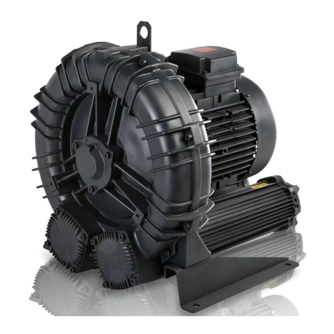
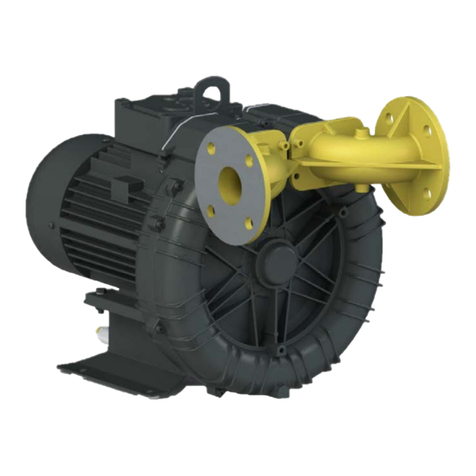
FPZ SCL K07R Quick guide

COMPRESSORI - ASPIRATORI A CANALE LATERALE ISTRUZIONI D’USO I
LATERAL CHANNEL BLOWERS - EXHAUSTERS USE INSTRUCTIONS GB
COMPRESSEURS - ASPIRATEURS A CANAL LATERAL INSTRUCTIONS F
SEITENKANALVERDICHTER - VAKUUMPUMPEN BAUREIHE BETRIEBSANLEITUNG D
COMPRESORES - ASPIRADORES DE CANAL LATERAL INSTRUCCIONES E
LEGGERE ATTENTAMENTE TUTTE LE ISTRUZIONI E CONSERVARLE I
PLEASE READ CAREFULLY ALL INSTRUCTIONS AND KEEP THEM FOR FUTURE REFERENCE GB
LIRE ATTENTIVEMENT TOUTES LES INSTRUCTIONS ET LES CONSERVER F
ALLE ANLEITUNGEN SIND SORGFÄLTIG ZU LESEN UND AUFZUBEWAHREN! D
SIRVASE LEER CUIDADOSAMENTE TODAS LAS INSTRUCCIONES Y CONSERVARLAS PARA FUTURA REFERENCIA E
SN 2365-3
Apparecchi Gruppo II , Categoria 3GD
Equipment of Group II, Category 3GD
Appareils Groupe II, Catégorie 3GD
Geräte der Gruppe II, Kategorie 3GD
Aparatos Grupo II, Categoría 3GD
FPZ S.p.A.
Via F.lli Cervi 16
20049 Concorezzo - (MB) - ITALIA
Tel. +39 039 69 09 811
Fax +39 039 60 41 296
www.fpz.com
®
SCL K07R / K08R / K09
K10 / K11 / K12
MD - MO
R
ENERGOEKONOM spol. s r.o., Wolkerova 433, CZ-250 82 Úvaly, Czech Republic, Tel.: +420 281 981 055, [email protected], www.energoekonom.cz

ENERGOEKONOM spol. s r.o., Wolkerova 433, CZ-250 82 Úvaly, Czech Republic, Tel.: +420 281 981 055, [email protected], www.energoekonom.cz
3/39
ENERGOEKONOM spol. s r.o., Wolkerova 433, CZ-250 82 Úvaly, Czech Republic, Tel.: +420 281 981 055, [email protected], www.energoekonom.cz
4/39
ENERGOEKONOM spol. s r.o., Wolkerova 433, CZ-250 82 Úvaly, Czech Republic, Tel.: +420 281 981 055, [email protected], www.energoekonom.cz
INDICE
1. ISTRUZIONI GENERALI 6
1.1 NORME DI SICUREZZA 6
1.2 CONDIZIONI DI UTILIZZO 6
1.3 IMMAGAZZINAGGIO - TRASPORTO 7
1.4INSTALLAZIONE 7
1.4.1 COMPRESSORE / ASPIRATORE ‘SCL K’ 7
1.4.2MOTOREELETTRICO 7
1.4.2.1 ALIMENTAZIONE E COLLEGAMENTO 7
1.4.2.2 SENSO DI ROTAZIONE 8
1.4.2.3 SENSORE DI TEMPERATURA 8
1.4.2.4 SCALDIGLIE ANTICONDENSA 8
1.5ESERCIZIO 8
1.5.1 CONTROLLI PRELIMINARI 8
1.5.2 MESSA IN FUNZIONE 8
1.5.3REGOLAZIONE 8
1.5.4 CONTROLLI PERIODICI 8
1.6MANUTENZIONE 8
1.7PROBLEMIDIFUNZIONAMENTO 9
1.8MARCATURA 10
1.8.1 DESCRIZIONE TARGA PRODOTTO 10
2. SCHEMI DI INSTALLAZIONE 11
2.1 COMPRESSORE 11
2.2 COMPRESSORE IN PARALLELO 11
2.3 ASPIRATORE 11
2.4 ASPIRATORE IN PARALLELO 11
2.5 LEGENDA ACCESSORI 11
I - 5/39
ENERGOEKONOM spol. s r.o., Wolkerova 433, CZ-250 82 Úvaly, Czech Republic, Tel.: +420 281 981 055, [email protected], www.energoekonom.cz
1. ISTRUZIONI GENERALI
1.1 NORME DI SICUREZZA
ATTENZIONE!
I compressori - aspiratori a canale laterale ‘SCL K’ per
categoria 3GD sono apparecchiature del gruppo II, per
l’uso in zone classificate con presenza di gas, vapori
e/o polveri combustibili non conduttive (zona 2 e zona
22). Essi sono progettati e costruiti in accordo alla
Direttiva ATEX 94/9/CE, Gruppo II Categoria 3GD,
secondo le norme europee EN 1127-1, EN 13463-1, EN
13463-5 e EN 14986.
Sono adatti al trasporto di gas se nelle condizioni di
funzionamento, la presenza di atmosfera esplosiva è
improbabile. Se ciò accade deve essere di breve durata.
Nel valutare la categoria dell’apparecchio, la parte
interna della macchina deve essere considerata come
l’ambiente in cui è installata.
I compressori/aspiratori a canale laterale ‘SCL K’
devono essere installati e mantenuti in accordo con le
norme impiantistiche e di manutenzione per ambienti
classificati contro il rischio di esplosione per presenza
di gas, vapori e/o polveri combustibili non conduttive
(zona 2 e zona 22) (esempio: EN 60079-14, EN 60079-17,
EN 61241-14, EN 61241-17 oppure altre norme/standard
nazionali).
Come tutti i macchinari e le apparecchiature con parti
in moto o poste sotto tensione, possono essere fonte di
grave pericolo se non propriamente utilizzate e/o
protette.
Viene demandato all'utilizzatore garantire che:
Tutte le operazioni di trasporto, montaggio,
installazione e allacciamento vengano eseguite da
personale qualificato, intendendo quel personale che
per formazione, istruzione, esperienza, come per
conoscenza di norme, prescrizioni, provvedimenti
antinfortunistici e condizioni di utilizzo e servizio, sia in
grado di effettuare ogni intervento necessario
riconoscendo ed evitando ogni possibile pericolo e/o
danno.
E’ SEVERAMENTE VIETATO:
- Utilizzare la macchina in installazioni non
industriali a meno che non siano state prese tutte
le precauzioni necessarie o misure protettive;
- utilizzare la macchina in luoghi dove la presenza di
polveri esplosive avvenga per un lungo periodo di
tempo o frequentemente;
- utilizzare la macchina in luoghi dove la presenza di
polveri esplosive è costante;
- l’aspirazione ed il trasporto di mezzi esplosivi,
infiammabili, aggressivi, corrosivi e/o nocivi;
- utilizzare la macchina in condizioni diverse dai
valori riportati nella targa prodotto;
- Il funzionamento a bocca chiusa dell’aspirazione
e/o della mandata;
- apportare modifiche o trasformazioni sulla
macchina, lavori di riparazione o manutenzione che
richiedono lo smontaggio della stessa.
Il personale esecutore delle operazioni di trasporto, montaggio,
installazione e allacciamento deve disporre di tutte le istruzioni
ed informazioni del caso, comprese eventuali prescrizioni locali e
a queste si deve attenere per lo svolgimento di qualsiasi
operazione.
Qualsiasi operazione anche indiretta su macchine ed apparecchi
è interdetta al personale non qualificato.
Devono venire soddisfatte in fase di installazione tutte le misure
di prevenzione prescritte, comprese eventuali prescrizioni locali
e/o particolari, e ne viene inibita la messa in servizio prima che le
macchine che le incorporano siano dichiarate conformi alla
Direttiva Macchine CE.
Si consideri che, esaminate le peculiarità costruttive e funzionali,
tali unità:
- in condizioni di esercizio possono raggiungere temperature
superficiali elevate, fino a 125 °C;
- non sopportano pressioni interne elevate, comunque non
superiori al valore Ps int max riportato nella targa prodotto;
- sono soggette a piccole perdite del fluido convogliato;
- possono presentare una rumorosità non accettabile per
determinate condizioni di installazione.
Gli accessori collegati all’unità devono essere conformi alla
direttiva ATEX 94/9/CE, il collegamento e le condutture di
aspirazione e mandata in materiale metallico o antistatico.
L’utilizzatore deve:
- Predisporre all’aspirazione un adeguato filtro in materiale
antistatico della categoria corrispondente, in accordo alla
Direttiva 94/9/CE, con grado di filtrazione massimo 25µm,
perdita di carico massima ∆P = 15mbar;
- deve valutare l’efficienza del filtraggio;
- deve eseguire un controllo periodico per effettuare la
pulizia o la sostituzione dello stesso.
I compressori - aspiratori ‘SCL K’ per categoria 3GD devono
essere collegati a terra mediante apposito elemento di
connessione antiallentante ed antirotazione; collegare a terra il
motore elettrico mediante il proprio collegamento di terra.
Il motore elettrico non deve essere aperto sotto tensione.
Al fine di limitare la formazione di strati di polvere, provvedere
alla regolare pulizia ed alla loro rimozione con idonee
attrezzature.
ATTENZIONE!! Non pulire la targhetta prodotto con solvente e/o
sostanze aggressive.
Pulire periodicamente la ventola di raffreddamento del motore per
evitare il surriscaldamento dello stesso.
All’utilizzatore non è permesso eseguire riparazioni o
manutenzioni, che richiedono di smontare la macchina.
In questi casi richiedere l’assistenza FPZ o quella del ns.
rivenditore.
Prima dell’installazione leggere attentamente quanto riportato in
questo manuale di istruzioni.
1.2 CONDIZIONI DI UTILIZZO
I compressori - aspiratori ‘SCL K’ per categoria 3GD sono adatti al
convogliamento in servizio continuo di aria e gas non esplosivi, non
infiammabili, non aggressivi, dove la presenza di atmosfera esplosiva
è improbabile.
Corpi solidi anche di piccole dimensioni e sporcizia possono causare
la formazione di scintille, dovute allo sfregamento delle stesse tra la
girante e la carcassa.
Anche i depositi di polvere all’interno della macchina possono
provocare la medesima reazione, e di conseguenza un aumento della
temperatura di esercizio.
Inoltre, la loro presenza può provocare la rottura delle palette della
girante, rendendo pericolosi i frammenti che vengono espulsi dalla
soffiante.
IMPORTANTE!
Predisporre all’aspirazione un adeguato filtro in materiale
antistatico della categoria corrispondente, in accordo alla
Direttiva 94/9/CE, con grado di filtrazione massimo 25µm,
perdita di carico massima ∆P = 15mbar.
I differenziali massimi di pressione ammessi (∆Pmax indicati nella
targa prodotto) non devono mai essere superati.
EVITARE ASSOLUTAMENTE IL FUNZIONAMENTO A BOCCA
CHIUSA.
Proteggere con adeguata valvola di sicurezza della categoria
corrispondente, in accordo alla Direttiva 94/9/CE.
Le caratteristiche sono soggette a variazione in funzione dei seguenti
fattori:
- variazione della pressione assoluta di aspirazione o di scarico
rispetto alla condizione di riferimento (1013 mbar);
- funzionamento a sistema misto (depressione in aspirazione e
contemporanea contro-pressione in mandata);
- convogliamento di gas avente peso specifico e/o temperatura
diversi dai dati di riferimento (1.23 kg/m3; 20 °C);
- variazione della velocità di rotazione rispetto al valore di
riferimento.
La temperatura ambiente, come la temperatura di aspirazione del
fluido convogliato, é ammessa nel campo di -15 ÷ +40 °C.
Va sempre assicurata una buona ventilazione delle unità
particolarmente se sottoposte a condizioni di esercizio gravose.
Le unità sottoposte a frequenti avviamenti o ad elevate temperature
ambientali possono essere soggette a problemi di surriscaldamento.
I - 6/39
ENERGOEKONOM spol. s r.o., Wolkerova 433, CZ-250 82 Úvaly, Czech Republic, Tel.: +420 281 981 055, [email protected], www.energoekonom.cz
1.3 IMMAGAZZINAGGIO - TRASPORTO
Immagazzinare in luogo asciutto possibilmente conservando
nell'imballo.
Non rimuovere le protezioni delle bocche.
Evitare di sovrapporre carichi agli imballi.
Se imballate, movimentare le scatole su una base d’appoggio il più
larga possibile per ottenere la massima stabilità. In ogni caso
movimentare con delicatezza evitando urti, strappi e scossoni.
Le movimentazioni (sollevare, spostare, trasportare, depositare)
devono essere svolte per quanto possibile utilizzando l'aiuto di
appositi mezzi. Il lavoro deve essere organizzato in modo che si
svolga con il minore rischio possibile ed in condizioni sicure e sane,
ad esempio:
- personale addetto con idoneità specifica e adeguatamente
informato;
- posizione di appoggio sicura e stabile;
- uso di idonei abiti da lavoro e dispositivi di protezione
individuali;
- zona di lavoro con spazi sufficienti, pavimenti regolari, senza
ostacoli;
Le unità di massa (m) superiori a 25 kg sono fornite di occhielli di
sospensione per la movimentazione. La massa è riportata nella
targa prodotto.
1.4 INSTALLAZIONE
1.4.1 COMPRESSORE - ASPIRATORE ‘SCL K’
E' importante che l'installazione avvenga in ambiente bene aerato e
dove la temperatura non superi i 40°C.
Se all'aperto, proteggere contro l'esposizione solare, evitare la
possibilità di ristagno di acqua particolarmente nel caso di
installazione dell’unità con asse verticale.
In condizioni di esercizio possono raggiungere temperature superficiali
elevate, fino a 125 °C. L’unità deve essere installata in modo tale da
evitare contatti accidentali con le superfici esterne, predisponendo una
adeguata protezione che garantisca sia il pericolo di ustioni sia il
normale raffreddamento della stessa.
IMPORTANTE !
L'ingresso nella soffiante di corpi estranei, anche di piccolissime
dimensioni, provoca gravi danni. I corpi estranei sono: polvere, sabbia,
calcinacci, impurità nei tubi, bave da taglio e filettatura, gocce e scorie
di saldatura, bave metalliche e residui di sigillanti prodotti durante la
connessione delle condotte.
La macchina può essere installata con l’asse in qualsiasi posizione. In
caso di installazione con l’asse verticale, deve essere prevista una
adeguata protezione in grado di impedire l’ingresso di corpi estranei
nel motore elettrico attraverso la calotta copriventola dello stesso.
Inoltre il sistema di protezione adottato, deve garantire il normale
raffreddamento del motore.
ATTENZIONE!!
Se la macchina è messa in servizio senza elementi di fissaggio essa
si potrà muovere improvvisamente a causa della coppia di spunto del
motore e capovolgersi.
La messa in servizio dell’unità non deve avvenire senza che la stessa
sia stata fissata ad una struttura o impianto idoneo alla stabilità.
Il mancato rispetto di queste prescrizioni può provocare gravissimi
danni a cose e persone.
Togliere le protezioni alle bocche solo per il collegamento definitivo.
IMPORTANTE !
Gli accessori collegati all’unità devono essere conformi alla
direttiva 94/9/CE, il collegamento e le condutture di aspirazione e
mandata in materiale metallico o antistatico.
Per connettere la macchina alla conduttura smontare le flange della
stessa e collegare mediante manicotti flessibili, evitando collegamenti
rigidi che possono indurre tensioni e innescare dannose vibrazioni.
Guarnire e serrare. Controllare periodicamente la tenuta ed il
serraggio.
Predisporre all’aspirazione un adeguato filtro in materiale
antistatico della categoria corrispondente, in accordo alla
Direttiva 94/9/CE, con grado di filtrazione massimo 25µm,
perdita di carico massima ∆P = 15mbar.
L’unità è provvista di un retino metallico montato nel condotto di
aspirazione e di mandata con grado di protezione IP20.
Nella necessità di regolazione della portata montare una valvola in
derivazione (ref. par. 1.5.3).
Dimensionare le tubazioni e scegliere accessori che contengano al
minimo le perdite di carico, pertanto:
- non montare tubi di diametro inferiore a quello delle bocche della
macchina; installando più macchine in parallelo, dimensionare in
proporzione il collettore e la linea principale;
- non impiegare gomiti, ma curve ad ampio raggio;
- non installare valvole con passaggio ridotto rispetto al nominale e
valvole di ritegno con otturatore contrastato da molla (la valvola
di ritegno con minore perdita di carico é quella a clapet
alleggerito);
- nei casi di impiego per l'ossigenazione, scegliere diffusori a
bassa resistenza di passaggio (bassa perdita di carico) e non
dimenticare che le candele e i setti porosi aumentano le perdite
di carico nel tempo a causa del progressivo intasamento.
Per evitare sovraccarichi causati da variazioni della pressione,
installare una valvola di sicurezza della categoria corrispondente, in
accordo alla direttiva 94/9/CE.
Collegare il motore e controllare il senso di rotazione prima della
connessione alle condotte (vedi paragrafo 1.4.2.2).
I compressori - aspiratori ‘SCL K’ sono già muniti nelle costruzioni
standard di silenziatori di aspirazione e mandata; nel caso di
aspirazione o scarico in atmosfera il rumore del flusso libero può
essere smorzato con silenziatori supplementari.
In ogni condizione é da evitare l'installazione delle unità su strutture
che possono trasmettere o amplificare il rumore e le vibrazioni
(serbatoi, piastre in lamiera ecc.).
Fare riferimento al Capitolo 2 per gli schemi di installazione.
Richiedere ulteriori informazioni come nel caso di necessità di
abbattimento generale della rumorosità mediante cabina afona.
1.4.2 MOTORE ELETTRICO
ATTENZIONE: PRIMA DI ESEGUIRE QUALSIASI OPERAZIONE
ASSICURARSI CHE LA LINEA NON SIA SOTTO TENSIONE.
IMPORTANTE !
Attenersi strettamente alle misure di sicurezza e
alle istruzioni contenute nei seguenti paragrafi, al
manuale d’istruzioni del motore ed alle istruzioni
complementarie per motori installati in atmosfera
pericolosa allegati.
Il motore elettrico è conforme alle seguenti Direttive:
- Direttiva Macchine CEE 98/37;
- Direttiva Bassa Tensione (LVD) CEE 73/23, modificata con CEE
93/68;
- Direttiva Compatibilità Elettromagnetica (EMC) CEE 89/336;
- Direttiva ATEX CEE 94/9, idoneo al gruppo II, alla zona 22
(categoria 3GD);
- Direttiva sulla limitazione dell’impiego di alcune sostanze
pericolose nelle apparecchiature elettriche ed elettroniche
(RoHS) CEE 2002/95.
1.4.2.1 ALIMENTAZIONE E COLLEGAMENTO
Per informazioni su questo argomento, far riferimento al manuale
d’istruzioni del motore ed alle istruzioni complementarie per motori
installati in atmosfera pericolosa allegati.
IMPORTANTE !
Connettere il cavo di messa a terra al relativo morsetto attraverso
il dispositivo antiallentante ed antirotazione.
Utilizzare dispositivi di protezione di sovracorrente con controllo di
fase in accordo con la DIN VDE 0660 Parte 104 – 09/8 e DIN VDE
0165 Parte 6.1.4.3.2. Questa protezione (termico o amperometrico) é
indispensabile contro i rischi di sovraccarico, in mancanza di una fase
in rete, frequenza di avviamenti troppo elevata, eccessiva variazione
della tensione o blocco del rotore.
IMPORTANTE !
Regolare il salvamotore sulla corrente nominale di targa come
valore massimo.
Non è consentito installare inverter all’unità. La frequenza di linea
deve essere quella indicata nella targa del motore elettrico.
ATTENZIONE!!
A causa delle alte temperature delle superfici esterne della
macchina, i cavi elettrici del collegamento al motore non devono
venire a contatto con le stesse.
Dimensionare i fusibili tenendo in considerazione le correnti di spunto,
particolarmente nel caso d’avviamento diretto. I fusibili non
costituiscono una protezione per il motore, ma solo una protezione
contro i corto circuiti.
I - 7/39
ENERGOEKONOM spol. s r.o., Wolkerova 433, CZ-250 82 Úvaly, Czech Republic, Tel.: +420 281 981 055, [email protected], www.energoekonom.cz
1.4.2.2 SENSO DI ROTAZIONE
I compressori – aspiratori ‘SCL K’ devono essere utilizzati in senso di
rotazione come indicato dalla freccia posizionata sul copriventola del
motore elettrico (Vedi fig.1).
Per verificare il senso di rotazione, alimentare/disalimentare per un
breve periodo il motore.
Per invertire l’eventuale errato senso di rotazione, far riferimento al
manuale d’istruzioni del motore allegato.
1.4.2.3 SENSORE DI TEMPERATURA
I compressori- aspiratori ‘SCL K’ per categoria 3GD sono equipaggiati
con motori elettrici dotati di sensore di temperatura Klixon (PTO) per il
controllo della temperatura dell’avvolgimento.
I sensori Klixon devono essere collegati su terminali aggiuntivi idonei
allo scopo in accordo allo schema di collegamento del sistema di
protezione.
1.4.2.4 SCALDIGLIE ANTICONDENSA
Su richiesta i motori elettrici per i compressori- aspiratori ‘SCL K’ per
categoria 3GD possono essere dotati di scaldiglie anticondensa.
Potenza termica e tensione di alimentazione: fare riferimento alle
indicazioni sulla targhetta del motore. Le scaldiglie anticondensa
devono essere collegate a speciali terminali dedicati presenti nella
scatola morsettiera, in accordo allo schema di collegamento.
ATTENZIONE!!
Non collegare le scaldiglie prima di aver disinserito il motore.
Durante il funzionamento del motore, le scaldiglie devono essere
disinserite.
1.5 ESERCIZIO
1.5.1 CONTROLLI PRELIMINARI
Prima della messa in servizio dell’unità eseguire i seguenti controlli:
- Nel caso sia trascorso un periodo prolungato prima della messa
in funzione dell’unità controllare il suo stato di conservazione.
- Controllare inoltre che tutte le protezioni di sicurezza siano
correttamente installate.
1.5.2 MESSA IN FUNZIONE
Alla messa in funzione dell'unità:
- Controllare la pressione o depressione di esercizio; è opportuno
prevedere l'impiego di adeguato manometro o vuotometro.
- Controllare la taratura della valvola di sicurezza.
- Misurare l'assorbimento del motore e verificare rispetto al valore
di targa.
- Tarare il salvamotore di conseguenza.
- Dopo un'ora di funzionamento, controllare che la corrente
assorbita non superi i valori ammessi.
ATTENZIONE!!
In condizioni di esercizio possono raggiungere temperature
superficiali elevate, fino a 125 °C;
1.5.3 REGOLAZIONE
I compressori - aspiratori ‘SCL K’ si auto regolano sul valore di
pressione differenziale richiesto all'utilizzo.
A pressioni differenziali crescenti corrispondono valori maggiori di
potenza assorbita ed incremento di temperatura, fino a raggiungere
condizioni di crisi per la macchina e/o il motore nel caso si superino i
valori di pressione massimi consentiti.
Le perdite di carico delle condotte sono frequentemente sottovalutate
ma sono fattori determinanti per la pressione differenziale di esercizio.
La regolazione della pressione differenziale di esercizio può essere
ottenuta, se non eliminando ostruzioni e strozzamenti, parzializzando
la portata.
Per diminuire la portata non strozzare l'aspirazione o la mandata ma
montare una valvola in derivazione.
1.5.4 CONTROLLI PERIODICI
Con l’unità in funzione eseguire periodicamente i seguenti controlli:
- Temperatura di mandata.
- Pressione e/o depressione d’esercizio.
- Assorbimento di corrente del motore elettrico.
Variazioni dei suddetti valori rispetto alle condizioni normali di lavoro
sono indizi di un non corretto funzionamento.
In tal senso è importante che le unità vengano sottoposte, da parte del
personale FPZ, ad ispezioni al fine di evitare guasti che possano
direttamente o indirettamente provocare danni.
Vedere il paragrafo 1.7 PROBLEMI DI FUNZIONAMENTO per
intervenire e/o prevenire possibili rotture o guasti.
Con l’unità ferma eseguire periodicamente i seguenti controlli:
- Deposito polvere: controllare e se necessario rimuovere i depositi
dalle superfici esterne dell’unità, che possono impedire il corretto
scambio di calore, mediante idonee attrezzature.
- Filtro in aspirazione: ogni 8/10 gg., controllare e se necessario
pulire o sostituire la cartuccia del filtro. In ambiente molto
polveroso sostituirla con più frequenza. La cartuccia sporca
determina forte resistenza in aspirazione in conseguenza
aumentano: il differenziale di pressione, la potenza assorbita, la
temperatura d’esercizio.
1.6 MANUTENZIONE
All’utilizzatore non è permesso eseguire riparazioni o
manutenzioni, che richiedono di smontare la macchina.
In questi casi richiedere l’assistenza FPZ o quella del ns.
rivenditore.
E' importante che le unità in esercizio vengano periodicamente
sottoposte, da parte del personale FPZ, ad ispezioni al fine di evitare
guasti che possano direttamente o indirettamente provocare danni.
Nelle normali condizioni di esercizio (valori riportati nella targa
prodotto) i cuscinetti della macchina devono essere sostituiti, da parte
del personale FPZ, dopo max. 20.000 ore di esercizio o al più tardi
dopo 4 anni.
Rimuovere se necessario depositi di polvere dalle superfici esterne
dell’unità, che possono impedire il corretto scambio di calore,
mediante idonee attrezzature.
Impegni, accordi o rapporti giuridici sono regolati dal contratto di
vendita corrispondente. I suddetti non sono in alcun modo limitati
dal contenuto del presente manuale.
La qualità dei materiali e delle lavorazioni è garantita come da
condizioni generali di vendita.
La garanzia decade per: danni subiti durante il trasporto; per
cattiva conservazione; inconvenienti da errato montaggio;
imperizia d'uso; superamento dei limiti di prestazione; eccessive
sollecitazioni meccaniche e/o elettriche.
Conservare l'imballo per eventuali impieghi futuri.
I - 8/39
Fig.1
ENERGOEKONOM spol. s r.o., Wolkerova 433, CZ-250 82 Úvaly, Czech Republic, Tel.: +420 281 981 055, [email protected], www.energoekonom.cz
1.7 PROBLEMI DI FUNZIONAMENTO
Problema Causa Soluzione
L’unità non si avvia Il cablaggio elettrico è errato;
Tensione di alimentazione non idonea;
La girante è bloccata.
Controllare il collegamento elettrico facendo
riferimento allo schema contenuto nella scatola
morsettiera.
Verificare che la tensione di alimentazione, misurata
ai morsetti del motore, sia nel +/-5% della tensione
nominale.
Far eseguire la riparazione della macchina a
personale FPZ.
Portata d’aria nulla o
insufficiente
Senso di rotazione errato;
Il filtro d’aspirazione è intasato.
Verificare che il senso di rotazione sia quello indicato
sul copriventola del motore.
Pulire o sostituire la cartuccia.
Assorbimento di corrente
superiore al valore ammesso
Cablaggio errato;
Caduta di tensione di alimentazione;
Il filtro d’aspirazione è intasato;
L’unità ha accumulato depositi interni;
L’unità sta operando ad una pressione e/o depressione
superiore al valore ammesso.
Controllare il collegamento elettrico facendo
riferimento allo schema contenuto nella scatola
morsettiera.
Ripristinare la tensione di alimentazione ai morsetti
nei valori consentiti.
Pulire o sostituire la cartuccia.
Far eseguire la pulizia interna della macchina a
personale FPZ.
Intervenire sull’impianto e/o sulla valvola di
regolazione per diminuire i differenziali di pressione.
Temperatura dell’aria di
mandata elevata
L’unità sta operando ad una pressione/depressione
superiore al valore ammesso;
Il filtro d’aspirazione è intasato;
I’unità ha accumulato depositi interni;
Tubazioni di aspirazione e/o mandata ostruite;
Temperatura dell’aria in aspirazione superiore ai 40°C.
Intervenire sull’impianto e/o sulla valvola di
regolazione per diminuire i differenziali di pressione.
Pulire o sostituire la cartuccia.
Far eseguire la pulizia interna della macchina a
personale FPZ.
Eliminare le ostruzioni.
Utilizzare scambiatori di calore per diminuire la
temperatura dell’aria in aspirazione.
Rumorosità anomala Il panno fonoassorbente è danneggiato;
La girante sfrega contro la carcassa;
a. L’unità sta operando ad una
pressione/depressione superiore al valore
ammesso;
b. Diminuzione dei giochi di assemblaggio a causa
di depositi interni (polvere, impurità dei tubi,
residui di processo, ecc.);
Cuscinetto usurato;
Posizione d’intallazione dell’unità non idonea.
Far sostituire il panno fonoassorbente a personale
FPZ.
Intervenire sull’impianto per diminuire i differenziali di
pressione.
Far eseguire la pulizia interna della macchina a
personale FPZ.
Far sostituire il cuscinetto a personale FPZ.
Installare le unità su strutture che non possano
trasmettere o amplificare il rumore (serbatoi, piastre
in lamiera, ecc.).
Vibrazioni anomale La girante è danneggiata;
La giranti ha accumulato depositi;
Fissaggio dell’unità errata.
Far eseguire la riparazione della macchina a
personale FPZ.
Far eseguire la pulizia interna della macchina a
personale FPZ.
Fissare l’unità mediante antivibranti.
I - 9/39
ENERGOEKONOM spol. s r.o., Wolkerova 433, CZ-250 82 Úvaly, Czech Republic, Tel.: +420 281 981 055, [email protected], www.energoekonom.cz
1.8 MARCATURA
La marcatura prevista per i compressori/aspiratori a canale laterale SCL K ..serie MS è la seguente:
II 3G c T3 / II 3D c T125 °C
Temperatura ambiente e di aspirazione ammissibile da –15 °C a +40 °C
II = gruppo II (superficie)
3 = categoria 3 (ZONA 2 / ZONA 22)
G = atmosfera esplosiva con presenza di gas e vapori
D = atmosfera esplosiva con presenza di polveri combustibili non conduttive
c = sicurezza costruttiva
T3 = classe di temperatura
T125°C = temperatura massima superficiale
-15°C / 40°C = temperatura ammissibile del aria aspirata e della temperatura ambiente
Corrispondenze tra zone pericolose, sostanze e categorie
Sostanza Zona pericolosa Categorie secondo Direttiva 94/9/CE
Gas, vapori o nebbie Zona 0 1G
Gas, vapori o nebbie Zona 1 2G oppure 1G
Gas, vapori o nebbie Zona 2 3G, 2G oppure 1G
Polveri Zona 20 1D
Polveri Zona 21 2D oppure 1D
Polveri Zona 22 3D, 2D oppure 1D
1.8.1 DESCRIZIONE TARGA PRODOTTO
N.B.:
I valori riportati in
corsivo
sono indicativi a titolo di esempio
I - 10/39
Marchio CE
N° di Matricola e
anno di produzione
Temperatura fluido e temperatura
ambiente ammissibile
Massa dell’apparecchio
Modello dell’apparecchio
Marcatura specifica
relativa alla protezione
dalle esplosioni
Marcatura di conformità al gruppo II
categoria 3 Gas e Polveri combustibili
non conduttive
Differenziali massimi di pressione ammessi
relativi alle frequenze 50 Hz / 60 Hz
Pressione interna massima
Marchio e indirizzo
del costruttore
m
18,5
kg Ps int max
1.8
bar abs
II 3G c T3 / II 3D c T125°C
Temperatura ambiente e di aspirazione
ammissibile da –15°C a +40°C
-
200
mbar / +
200
mbar
-
175
mbar / +
175
mbar
Via F.lli Cervi, 16
20049 CONCOREZZO (MB) - ITALY
FPZ S.p.A.
Tipo SCL
K09-MD
MOR
Mat.
C12345
2008
Hz ∆P max
50
60
ENERGOEKONOM spol. s r.o., Wolkerova 433, CZ-250 82 Úvaly, Czech Republic, Tel.: +420 281 981 055, [email protected], www.energoekonom.cz
2. SCHEMI DI INSTALLAZIONE
2.1 COMPRESSORE
2.2 COMPRESSORE IN PARALLELO
2.5 LEGENDA ACCESSORI
2.3 ASPIRATORE
2.4 ASPIRATORE IN PARALLELO
I - 11/39
Item Denominazione
1
Filtro - Filtro in linea
(2)
Silenziatore
3
Manicotto flessibile
4
Manometro – Vuotometro
5
Valvola di sicurezza
6
Valvola
7 Valvola di ritegno
(x) SE NECESSARIO
ENERGOEKONOM spol. s r.o., Wolkerova 433, CZ-250 82 Úvaly, Czech Republic, Tel.: +420 281 981 055, [email protected], www.energoekonom.cz
INDEX
1. GENERAL INSTRUCTIONS 13
1.1 SAFETY INSTRUCTIONS 13
1.2WORKINGCONDITIONS 13
1.3 STORING - TRANSPORTATION 14
1.4INSTALLATION 14
1.4.1 ‘SCL K’ BLOWER - EXHAUSTER 14
1.4.2 ELECTRIC MOTOR 14
1.4.2.1 POWER SUPPLY AND CONNECTION 14
1.4.2.2 ROTATION DIRECTION 15
1.4.2.3 TEMPERATURE SENSOR 15
1.4.2.4 ANTI-CONDENSATE HEATERS 15
1.5OPERATION 15
1.5.1 PRELIMINARY CHECKS 15
1.5.2STARTINGUP 15
1.5.3 REGULATING 15
1.5.4 PERIODIC CHECKS 15
1.6MAINTENANCE 15
1.7 TROUBLESHOOTING 16
1.8MARKING 17
1.8.1 PRODUCT PLATE DESCRIPTION 17
2. INSTALLATION SKETCHES 18
2.1 PRESSURE SERVICE 18
2.2 PARALLEL PRESSURE SERVICE 18
2.3 VACUUM SERVICE 18
2.4 PARALLEL VACUUM SERVICE 18
2.5 LIST ACCESSORIES 18
GB - 12/39
ENERGOEKONOM spol. s r.o., Wolkerova 433, CZ-250 82 Úvaly, Czech Republic, Tel.: +420 281 981 055, [email protected], www.energoekonom.cz

1. GENERAL INSTRUCTIONS
1.1 SAFETY INSTRUCTIONS
WARNING!
‘SCL K’ side channel compressors – suction pumps for
category 3GD are units belonging to group II, for use in
classified areas with the presence of gas, vapours
and/or non-conductive dust (zone 2 and zone 22). These
units were designed and built in compliance with the
Directive ATEX 94/9/EC, Group II Category 3GD,
according to European regulations EN 1127-1, EN
13463-1, EN 13463-5 and EN 14986.
They are suitable for handling gas under working
conditions in which the presence of explosive air is
improbable. If these do occur they must be used for a
short period of time.
In assessing the category for this equipment, the inner
part of the machine must be considered as the
installation environment.
‘SCL K’ side channel compressors – suction pumps
must be installed and maintained in compliance with
system and maintenance requirements for areas
classified against risk of explosions due to the
presence of gas, vapours and/or non-conductive dust
(zone 2 and zone 22) (example: EN 60079-14, EN 60079-
17 EN 61241-14, EN 61241-17 or other national
rules/standards).
As with all machinery and equipment with moving or
live parts, they may be the source of serious danger if
they are not used and/or protected properly.
The user is responsible for ensuring that:
All transporting, assembly, installation, and connecting
up are done by trained personnel, meaning personnel
that have training, instruction, experience, and
knowledge of the standards, instructions, accident
prevention provisions, and operating and service
conditions that make them able to carry out all the
works necessary and to avoid any possible danger
and/or harm.
THE FOLLOWING ARE STRICTLY FORBIDDEN:
- Using the machine in non-industrial settings,
unless all the necessary precautions or protective
measures have been taken.
- Using the machine in places where explosive dust
is present for long periods of time, or frequently.
- Using the machine in places where the presence of
explosive dust is constant.
- Extracting and transporting explosive,
inflammable, aggressive, and/or harmful
substances.
- Use the machine in conditions different from the
numbers on the product plate.
- Running the machine with the intake and/or
delivery line closed.
- Modifying or transforming the machine.
- Repairs or maintenance that involve disassembling
the machine.
Personnel responsible for transporting, assembling, installing,
and connecting up the machine must have all the instructions
and information they need, including any local rules, and are to
comply with the same when carrying out any operation.
Unqualified personnel are forbidden to carry out any work on the
machine or equipment, even indirectly.
All the preventive measures are to be applied at the time of
installation, including any local and/or specific rules, and the
machine is not to be commissioned until the equipment into
which it is incorporated has been declared as conforming to the
EC Machinery Directive.
Bear in mind that, due to their specific construction and
operating characteristics, these units:
- May reach high surface temperatures of up to 125°C under
working conditions.
- The unit does not withstand high internal pressures, in any
case not over Ps int max number specified on the product
plate.
- Are subject to minor leakage of the fluid transported.
- May produce noise levels that are unacceptable for certain
installation conditions.
The accessories connected to the unit must conform to the ATEX
94/9/EC Directive, and the intake and delivery connections and
hoses must be made of anti-static metallic material.
The user is to:
- Install a suitable filter for suction in antistatic material from
the corresponding category, in compliance with the Directive
94/9/EC, maximum filtration degree 25µm, maximum charge
losses ∆p = 15 mbar.
- Assess the efficiency of filtration.
- Routinely check the cleanliness of the filter and change it
when necessary.
Category 3GD ‘SCL K’ blowers - exhausters must be earthed by
means of a specific connection that cannot come loose or rotate.
Connect the electric motor to the earth using its earth
connection.
The electric motor must not be opened while live.
In order to limit the formation of layers of dust, clean regularly
and use suitable equipment to remove the dust.
WARNING!! Do not clean the product plate with solvents and/or
aggressive substances.
The user is not permitted to carry out repairs or maintenance that
require disassembling the machine.
Where this is necessary call in FPZ or our official representative.
Before installing the equipment, read this instruction manual
carefully.
1.2 WORKING CONDITIONS
Category 3GD ‘SCL K’ blowers - exhausters are suitable for
transporting non-explosive, non-inflammable, and non-aggressive air
and gas in continuous service, in places in which the presence of an
explosive atmosphere is improbable.
Solid items, even of small size, and dirt can cause sparks due to them
being dragged between the impeller and the casing.
Even dust deposits inside the machine can cause the same reaction,
and this results in an increase in the working temperature.
In addition, the presence of these particles can cause the blades of
the impeller to break, producing dangerous fragments that are
expelled by the blower.
IMPORTANT!
Install a suitable filter for suction in antistatic material from the
corresponding category, in compliance with the Directive
94/9/EC, maximum filtration degree 25µm, maximum charge
losses ∆p = 15 mbar.
The maximum pressure differential allowed (∆Pmax indicated on the
machine’s nameplate) must never be exceeded.
DO NOT USE THE MACHINE WITH THE INLET (INTAKE) CLOSED
UNDER ANY CIRCUMSTANCES.
Use a suitable safety valve of the relevant category as a means of
protection in compliance with Directive 94/9/EC.
The machine’s characteristics are subject to change in relation to the
following factors:
- Variation of the absolute intake or delivery pressure compared to
the standard condition (1013 mbar).
- Running as a mixed system (vacuum on the intake side and
simultaneous back-pressure on the delivery side).
- Transporting gas with a specific weight and/or temperature that
differs from the standard (1,23 kg/m3/ 20°C).
- Variation of the rotation speed compared to the standard value.
The ambient temperature and the intake temperature for the fluid
transported, must be between - 15 and + 40 °C.
The units must always be well ventilated especially when subjected to
demanding working conditions.
Units that start up frequently or work in high ambient temperatures
may be subject to overheating.
GB - 13/39
ENERGOEKONOM spol. s r.o., Wolkerova 433, CZ-250 82 Úvaly, Czech Republic, Tel.: +420 281 981 055, [email protected], www.energoekonom.cz

1.3 STORING - TRANSPORTATION
Store in a dry place and keep the packing if possible.
Do not remove the protective covers over the openings.
Do not place loads on the machine boxes.
If packed, support the boxes over as wide a base as possible to obtain
maximum stability. In any event, move the unit carefully, avoiding
impacts, jerks, or jolting.
Handling (lifting, moving, transporting, and putting down) must be
carried out using suitable means wherever possible. This work must
be organised in such a way that it poses the least risk possible and
provides safe, healthy conditions. For example:
- Personnel that are specifically suitable and adequately
informed.
- A safe and stable support position.
- Use of suitable working clothes and personal protective
equipment.
- Work areas that are sufficiently spacious, even floors, no
obstacles.
Units with a weight (m) of more than 25 kg are fitted with lifting lugs for
moving them. The weight is shown on the product plate.
1.4 INSTALLATION
1.4.1 ‘SCL K’ BLOWER - EXHAUSTER
It is important that the unit is installed in well ventilated places in which
the temperature does not exceed 40°C.
If installed outdoors, protect the unit against the sun’s rays, avoid any
pools of water forming, especially when installed with the unit along a
vertical axis.
The unit may reach high surface temperatures of up to 125°C under
working conditions. The unit must be installed in such a way as to
avoid accidental contact with the external surfaces, by providing
adequate protection that guards against scalding and also allows the
unit to cool normally.
IMPORTANT!
Any foreign bodies that enter the intake, even if very small in size,
cause serious damage. These foreign bodies include: dust, sand,
scale, impurities in the pipes, burrs from cutting and threading,
droplets and runs from welds, metal splinters and residue of sealants
used when connecting up the pipes.
This machine can be installed with its axis in any position. When
installed with the axis in a vertical position, adequate protection must
be provided to prevent foreign objects getting into the electric motor
via the fan cowling. In addition, the protection used must allow the
motor to cool normally.
WARNING!
If the machine is started without the adequate fixing in place, it may
move suddenly due to the thrust torque from the motor and turn
upside down.
This unit must not be commissioned until it has been anchored to a
structure or plant that is sufficiently stable.
Failure to comply with these instructions may result in very serious
damage to people or property.
Only remove the covers over the openings for final connection.
IMPORTANT!
The accessories connected to the unit must conform to the ATEX
94/9/EC Directive, and the intake and delivery connections and
hoses must be made of anti-static metallic material.
To connect the machine to the piping, remove the flanges and connect
using flexible hoses. Do not use rigid connections as these may
cause stress and harmful vibrations. Insert gaskets and tighten.
Periodically check the seals and air-tightness of the unit.
Install a suitable filter for suction in antistatic material from the
corresponding category, in compliance with the Directive
94/9/EC, maximum filtration degree 25µm, maximum charge
losses ∆p = 15 mbar.
This unit has a metal mesh on the intake and delivery pipe that
provides a protection level of IP20.
When the flow rate has to be regulated, fit a by-pass valve (see
paragraph 1.5.3).
Size the piping and choose accessories that keep leaks to a minimum,
and so:
- Do not fit pipes of a diameter smaller than the openings in the
machine. When installing a number of machines in parallel, size
the manifold and the main line proportionately.
- Do not use elbows but large radius bends.
- Do not fit valves with an internal diameter that is smaller than the
nominal pipe diameter and non-return valves with a spring-loaded
shutter (non-return valves that cause the least leakage are ones
with a light shutter).
- When using to supply oxygen, choose diffusers with a low
resistance (low pressure loss) and do not forget that the pressure
loss caused by plugs and porous sieves increases over time due
to gradual clogging.
Use a suitable safety valve of the relevant category as a means of
protection against excess loading caused by pressure fluctuations, in
compliance with Directive 94/9/EC.
Connect up the motor and check that it rotates in the correct direction
before connecting up the pipes (see paragraph 1.4.2.2).
‘SCL K’ blowers - exhausters are already fitted with silencers on
the intake and delivery sides as standard equipment. When using for
extracting or discharging into the air, the noise caused by the free flow
can be silenced by adding additional silencers.
In all cases the unit must not be installed on structures that can
transmit or amplify noise and vibrations (tanks, steel plates, etc.).
See Chapter 2 for Installation Diagrams.
In cases such as the need to reduce noise generally by means of a
soundproof cabin ask for further information.
1.4.2 ELECTRIC MOTOR
WARNING! BEFORE DOING ANYTHING ELSE, CHECK THAT THE
LINE IS NOT LIVE.
IMPORTANT!
Comply strictly with the safety measures and
instructions contained in the paragraphs that
follow, the instruction manual for the motor, and
the additional instructions for motors installed in
dangerous environments, that are enclosed.
The electric motor conforms to the following Directives:
- Machinery Directive CEE 98/37.
- Low Voltage Directive (LVD) CEE 73/23, amended by CEE 93/68.
- Electromagnetic Compatibility Directive (EMC) CEE 89/336.
- ATEX CEE 94/9 Directive, suitable for group II, in area 22
(category 3GD).
- Directive on limiting the use of some hazardous substances in
electrical and electrical equipment (RoHS) CEE 2002/95.
1.4.2.1 POWER SUPPLY AND CONNECTION
For information on this topic see the instruction manual for the motor
and the additional instructions for motors installed in dangerous
environments, which are enclosed.
IMPORTANT!
Connect the earth cable to the relevant terminal by means of a
device that cannot work loose or rotate.
Use devices to protect against excess currents with a phase control in
terms of DIN VDE 0660 Part 104 – 09/8 and DIN VDE 0165 Part
6.1.4.3.2. This (trip switch or amperometric) protective device is
essential to guard against risks of overloading should a phase be
down on the grid, start-up frequencies be too high, or excessive
fluctuations in voltage or blockage of the rotor occur.
IMPORTANT!
Set the motor protection device with the nominal current shown
on the nameplate as a maximum value.
Do not fit an inverter in the unit. The power supply frequency must be
as indicated on the nameplate on the electric motor.
WARNING!
Due to the high surface temperatures reached by the machine’s
external surfaces, the electric cables connected to the motor
must not touch it.
Size the fuses to suit the peak current, especially where direct starting
is used. Fuses do not provide protection for the motor but simply
protect against short-circuits.
GB - 14/39
ENERGOEKONOM spol. s r.o., Wolkerova 433, CZ-250 82 Úvaly, Czech Republic, Tel.: +420 281 981 055, [email protected], www.energoekonom.cz
1.4.2.2 ROTATION DIRECTION
‘SCL K’ blowers - exhausters must be used with the direction of
rotation as indicated by the arrow on the fan cowling on the electric
motor (see Fig 1.).
To check the direction of rotation, switch the power to the motor on for
a short period of time and then off again.
To reverse the incorrect direction of rotation, see the enclosed
instruction manual for the motor.
1.4.2.3 TEMPERATURE SENSOR
Category 3GD ‘SCL K’ blowers - exhausters are fitted with electric
motors that are equipped with a Klixon (PTO) temperature sensor that
monitors the temperature on the winding.
The Klixon sensors must be connected to additional terminals that are
suitable for this purpose, according to the wiring diagram for the
protection system.
1.4.2.4 ANTI-CONDENSATE HEATERS
Upon request, electric motors for ‘SCL K’ blowers - exhausters
may be fitted with anti-condensate heaters.
Thermal power and power supply voltage: See the data on the
motor’s nameplate. The anti-condensate heaters must be connected
to special terminals in the terminal box, according to the wiring
diagram enclosed.
WARNING!
Do not connect up the heaters while the motor is on/running.
When the motor is running, the heaters must be switched off.
1.5 OPERATION
1.5.1 PRELIMINARY CHECKS
Before starting the unit, carry out the following checks:
- If a long time has passed before the unit is started for the first
time, check its condition.
- Also check that all the safety devices have been installed
correctly.
1.5.2 STARTING UP
When starting up the unit:
- Check the operating pressure or vacuum. A suitable pressure or
vacuum gauge should be used.
- Check the setting on the safety valve.
- Measure the power absorption on the motor and check against
the value indicated on the nameplate.
- Set the motor protective device accordingly.
- Once the unit has been running for an hour, check that the
power absorption does not exceed the values allowed.
WARNING!
The unit may reach high surface temperatures of up to 125°C
under working conditions.
1.5.3 REGULATING
‘SCL K’ blowers - exhausters regulate themselves in relation to the
working pressure differential.
If the maximum pressure values are exceeded higher pressure
differentials are accompanied by greater power absorption and higher
temperatures, until critical conditions are reached for the machine
and/or the motor.
Pressure losses in the pipes are often underestimated, but are
determining factors in terms of the working pressure differential.
The working pressure differential can be affected by choking the flow
rate, in addition to any obstructions or narrowing.
In order to reduce the flow rate do not choke the intake or delivery,
rather use a by-pass valve.
1.5.4 PERIODIC CHECKS
While the unit is running, carry out the following checks from time to
time:
- Delivery temperature.
- Working pressure and/or vacuum.
- Power absorption on the electric motor.
If these values vary from the normal working conditions, this indicates
that the unit is not working properly.
This means that it is important to have the unit inspected by FPZ
personnel in order to avoid faults that may cause damage directly or
indirectly.
See paragraph 1.7 – TROUBLESHOOTING to be dealt with and/or
avoiding possible breakage or faults.
While the unit is stopped, carry out the following checks from time to
time:
- Dust build up: Check, and if necessary remove any dust built up
on the external surfaces of the unit that may impede correct heat
exchange, using suitable equipment.
- Intake filter: Every 8 to 10 days check and if necessary clean or
replace the filter cartridge. In very dusty conditions, replace it
more frequently. A dirty cartridge causes high suction resistance,
which result sin increases in: the pressure differential, the power
absorption, and the working temperature.
1.6 MAINTENANCE
The user is not permitted to carry out repairs or maintenance that
require disassembling the machine.
Where this is necessary call in FPZ or our official representative.
It is important to have the unit inspected by FPZ personnel from time
to time in order to avoid faults that may cause damage directly or
indirectly.
Under normal working conditions (values shown on the product plate)
the machine’s bearings should be replaced by FPZ personnel after
20,000 working hours max or 4 years.
If necessary remove any dust built up on the external surfaces of the
unit that may impede correct heat exchange, using suitable
equipment.
Commitments, agreements or legal relationships are governed by
the corresponding sales contract. The above items are in no way
limited by the contents of this manual.
The quality of the materials and of the workmanship is
guaranteed as set out by the standard conditions of sales.
The guarantee is not valid for the following: damage incurred
during transport; inadequate storage; faulty installation; incorrect
use; exceeding performance limits; electrical or mechanical miss-
use.
Store the packaging for possible future use.
I - 7/xxGB - 15/39
Fig.1
ENERGOEKONOM spol. s r.o., Wolkerova 433, CZ-250 82 Úvaly, Czech Republic, Tel.: +420 281 981 055, [email protected], www.energoekonom.cz

1.7 TROUBLESHOOTING
Problem Cause Solution
The unit does not start The electric wiring is incorrect.
The power supply voltage is not suitable.
The impeller is stuck.
Check the electric wiring against the wiring diagram in
the terminal board box.
Check that the power supply voltage, measured at
the motor’s terminals, is within ± 5% of the nominal
voltage.
Get FPZ personnel to repair the machine.
Air flow rate zero or
insufficient
Rotation direction incorrect.
Intake filter clogged.
Check that the direction of rotation is as indicated on
the motor’s fan cowling.
Clean or replace the cartridge.
Power absorption exceeds
the maximum allowed
Wiring incorrect.
Voltage drop on the power supply.
Intake filter clogged.
Deposits have built up inside the unit.
The unit is operating at a pressure and/or vacuum that
exceeds that allowed.
Check the electric wiring against the wiring diagram in
the terminal board box.
Return the power supply voltage at the terminals to
within the values allowed.
Clean or replace the cartridge.
Get FPZ personnel to clean the machine internally.
Adjust the plant and/or the regulating valve to reduce
the pressure differentials.
Delivery air temperature high The unit is operating at a pressure / vacuum that exceeds
that allowed.
Intake filter clogged.
Deposits have built up inside the unit.
Intake and/or delivery piping clogged.
Air temperature at intake exceeds 40°C.
Adjust the plant and/or the regulating valve to reduce
the pressure differentials.
Clean or replace the cartridge.
Get FPZ personnel to clean the machine internally.
Remove the obstructions.
Use a heat exchanger to reduce the air temperature
at the intake.
Excessive noise The soundproofing fabric is damaged.
The impeller is scraping against the chassis:
a. The unit is operating at a pressure / vacuum that
exceeds that allowed.
b. The play allowed during assembly has been
reduced due to internal deposits (dust, impurities
in the pipes, process residue, etc.).
Bearing worn.
Installation position of the unit not suitable.
Get FPZ personnel to replace the soundproofing
fabric.
Adjust the plant to reduce the pressure differentials.
Get FPZ personnel to clean the machine internally.
Get FPZ personnel to replace the bearing.
Install the units on structures that cannot transmit or
amplify the noise (tanks, steel plating, etc.).
Abnormal vibrations The impeller is damaged.
Deposits have built up on the impeller.
The unit is fixed incorrectly.
Get FPZ personnel to repair the machine.
Get FPZ personnel to clean the machine internally.
Fix the unit on anti-vibration supports.
GB - 16/39
ENERGOEKONOM spol. s r.o., Wolkerova 433, CZ-250 82 Úvaly, Czech Republic, Tel.: +420 281 981 055, [email protected], www.energoekonom.cz

1.8 MARKING
Required marking for SCL K side channel compressors/suction pumps of the MS series is as follows:
II 3G c T3 / II 3D c T125 °C
Admissible room temperature and suction temperature from –15 °C to +40 °C
II = group II (surface)
3 = category 3 (ZONE 2 / ZONE 22)
G = explosive atmosphere with the presence of gas and vapours
D = explosive atmosphere with the presence of combustible non-conductive dust
c = constructive safety
T3 = temperature class
T125°C = maximum surface temperature
-15°C/40°C = admissible temperature range of suctioned air and room temperature
Correspondences between dangerous areas, substances and categories
Substance Danger area Categories according to Directive 94/9/EC
Gas, vapour or mist Zone 0 1G
Gas, vapour or mist Zone 1 2G or 1G
Gas, vapour or mist Zone 2 3G, 2G or 1G
Dust Zone 20 1D
Dust Zone 21 2D or 1D
Dust Zone 22 3D, 2D or 1D
1.8.1 PRODUCT PLATE DESCRIPTION
Note:
The numbers in
italics
are indicated as examples only.
EC Mark
Serial N° and
year of production
Admissible flow temperature
and room temperature
Mass of the unit
Unit model
Specific marking regarding
protection against explosions
Marking showing conformity to the group
II category 3 combustible non
conductive Gas and Dust
Maximum differential pressure range
permitted in relation to the frequencies
50 Hz / 60 Hz
Maximum internal pressure
Manufacturer’s address
and mark
GB - 17/39
m
18,5
kg Ps int max
1.8
bar abs
II 3G c T3 / II 3D c T125°C
Temperatura ambiente e di aspirazione
ammissibile da –15°C a +40°C
-
200
mbar / +
200
mbar
-
175
mbar / +
175
mbar
Via F.lli Cervi, 16
20049 CONCOREZZO (MB) - ITALY
FPZ S.p.A.
Tipo SCL
K09-MD
MOR
Mat.
C12345
2008
Hz ∆P max
50
60
ENERGOEKONOM spol. s r.o., Wolkerova 433, CZ-250 82 Úvaly, Czech Republic, Tel.: +420 281 981 055, [email protected], www.energoekonom.cz

2. INSTALLATION SKETCHES
2.1 PRESSURE SERVICE
2.2 PARALLEL PRESSURE SERVICE
2.5 LIST ACCESSORIES
2.3 VACUUM SERVICE
2.4 PARALLEL VACUUM SERVICE
GB - 18/39
Item Denomination
1
Filter – Inline filter
(2)
Silencer
3
Flexible coupling
4
Pressure – Vacuum gauge
5
Safety valve
6
Valve
7 Non return valve
(x) IF NECESSARY
ENERGOEKONOM spol. s r.o., Wolkerova 433, CZ-250 82 Úvaly, Czech Republic, Tel.: +420 281 981 055, [email protected], www.energoekonom.cz

SOMMAIRE
1. INSTRUCTIONS GENERALES 20
1.1 CONSIGNES DE SECURITE 20
1.2 CONDITIONS D’UTILISATION 20
1.3 STOCKAGE ET TRANSPORT 21
1.4INSTALLATION 21
1.4.1 COMPRESSEUR - ASPIRATEUR ‘SCL K’ 21
1.4.2 MOTEUR ELECTRIQUE 21
1.4.2.1 ALIMENTATION ET BRANCHEMENT 21
1.4.2.2 SENS DE ROTATION 22
1.4.2.3 CAPTEUR DE TEMPERATURE 22
1.4.2.4 ELEMENT CHAUFFANT ANTICONDENSATION 22
1.5 MARCHE 22
1.5.1 CONTROLES PRELIMINAIRES 22
1.5.2 MISE EN SERVICE 22
1.5.3REGLAGE 22
1.5.4 CONTROLES REGULIERS 22
1.6ENTRETIEN 22
1.7 PROBLEMES DE FONCTIONNEMENT 23
1.8MARQUAGE 24
1.8.1 DESCRIPTION PLAQUETTE DU PRODUIT 24
2. SCHÉMA DE INSTALLATION 25
2.1SOUFFLANTE 25
2.2 SOUFFLANTE EN PARALLÈLE 25
2.3POMPEÀVIDE 25
2.4 POMPE À VIDE EN PARALLÈLE 25
2.5 LISTE DES ACCESSOIRES 25
F - 19/39
ENERGOEKONOM spol. s r.o., Wolkerova 433, CZ-250 82 Úvaly, Czech Republic, Tel.: +420 281 981 055, [email protected], www.energoekonom.cz

1. INSTRUCTIONS GENERALES
1.1 CONSIGNES DE SECURITE
ATTENTION !
Les compresseurs – aspirateurs à canal latéral ‘SCL K’
pour la catégorie 3GD sont des appareils du groupe II.
Ils sont destinés à un usage dans les zones classées
comme contenant des gaz, des vapeurs et/ou des
poussières combustibles non conductibles (zone 2 et
zone 22). Ils ont été conçus et fabriqués conformément
à la Directive ATEX 94/9/CE, Groupe II Catégorie 3GD,
suivant les normes européennes EN 1127-1, EN 13463-
1, EN 13463-5 et EN 14986.
Ils sont adaptés au transport de gaz dans un
environnement où la présence d’une atmosphère
explosive est peu probable. Dans le cas contraire, le
phénomène doit être de courte durée.
Lors de l’évaluation de la catégorie de la machine, il
faut prendre en compte la partie interne de cette
dernière tout comme l’environnement où elle est
installée.
Les compresseurs / aspirateurs à canal latéral ‘SCL K’
doivent être installés et entretenus conformément aux
normes pour les installations et aux normes d’entretien
pour les milieux classés contre le risque d’explosion dû
à une présence de gaz, vapeurs et/ou poussières
combustibles non conductibles (zone 2 et zone 22)
(exemple: EN 60079-14, EN 60079-17, EN 61241-14, EN
61241-17 ou autres normes/standards nationaux).
Comme tous les outillages et les équipements
composés de parties en mouvement ou sous tension,
ils peuvent constituer de graves sources de danger s'ils
ne sont pas correctement utilisés et/ou protégés.
L’utilisateur est prié de garantir ce qui suit :
Toutes les opérations de transport, montage,
installation, branchement doivent être effectuées par du
personnel qualifié. A savoir, les employés qui, par leur
formation, apprentissage, expérience tout comme par
leur connaissance des normes, recommandations,
mesures de prévention des accidents du travail ainsi
que des conditions d’utilisation et de fonctionnement,
sont en mesure d’effectuer toute intervention
nécessaire sur la machine et de reconnaître et éviter les
éventuels dangers et/ou dommages.
IL EST STRICTEMENT INTERDIT :
- de monter la machine dans des installations non
industrielles, à moins que toutes les précautions et
les mesures de protection nécessaires aient été
prises.
- d’utiliser la machine dans des endroits où la
présence de poussières explosives se produit
pendant une longue période ou fréquemment.
- d’utiliser la machine dans des endroits où la
présence de poussières explosives est constante.
- d’aspirer et de transporter des matières explosives,
inflammables, agressives et/ou nocives.
- d’utiliser la machine dans des conditions
différentes des valeurs indiquées sur la plaque du
produit.
- de faire fonctionner l’aspiration et/ou le
refoulement en débit nul.
- d’apporter des modifications ou transformations à
la machine et de faire des travaux de réparation ou
d’entretien exigeant qu’elle soit démontée.
Le personnel chargé des opérations de transport, montage,
installation et branchement, doit disposer de toutes les
instructions et informations nécessaires, y compris les
éventuelles recommandations locales, et les respecter quelle que
soit le travail à réaliser.
Toute opération, même indirecte, sur les machines et les
appareils est interdite au personnel non qualifié.
Pendant la phase d’installation, toutes les mesures de
préventions prescrites doivent être respectées, y compris les
éventuelles recommandations locales et/ou spéciales. Il est
interdit de mettre en service le dispositif tant que les machines
sur lesquelles il est monté ne sont pas déclarées conformes à la
Directive Machines CE.
Une fois que les particularités de fabrication et fonctionnelles des
unités ont été examinées, il faut tenir compte du fait que :
- en conditions de fonctionnement, elles peuvent atteindre des
températures superficielles élevées, jusqu’à 125°C.
- elles ne supportent pas des pressions internes élevées et
quoi qu’il en soit non supérieures à la valeur Ps int max
indiquée sur la plaque de la machine.
- de petites fuites du fluide transporté peuvent se produire.
- elles peuvent présenter un niveau de nuisance sonore
incompatible avec certaines conditions d’installation.
Les accessoires branchés à l’unité doivent être conformes à la
directive ATEX 94/9/CE, le branchement et les conduites
d’aspiration et de refoulement doivent être en matériau métallique
ou antistatique.
L’utilisateur doit :
- Prévoir l’utilisation d’un filtre adéquat en aspiration, en
matériel antistatique de la catégorie correspondante,
conformément à la Directive 94/9/CE, max. degré de filtrage
25µm, max. parte de charge ∆p = 15 mbar.
- doit évaluer l’efficacité du filtrage.
- doit effectuer un contrôle périodique en vue de nettoyer ou
remplacer le filtre.
Les compresseurs - aspirateurs ‘SCL K’ pour catégorie 3GD
doivent être raccordés à la terre par le biais d’un élément de
connexion spécifique, anti-relâchement et anti-rotation. Le
moteur électrique doit quant à lui être raccordé à la terre par le
biais de son propre dispositif.
Il ne faut pas ouvrir le moteur électrique lorsqu’il est sous
tension.
Pour limiter la formation de couches, nettoyer et éliminer la
poussière régulièrement à l’aide d’outils adéquats.
ATTENTION !! Ne jamais nettoyer la plaquette du produit avec du
solvant et/ou des substances agressives.
L’utilisateur n’a pas le droit de faire des opérations de réparation
ou d’entretien nécessitant le démontage de la machine.
En cas de besoin, demander au service d’assistance de FPZ ou
de notre revendeur.
Avant l’installation, lire attentivement les instructions indiquées
dans ce manuel.
1.2 CONDITIONS D’UTILISATION
Les compresseurs - aspirateurs ‘SCL K’ pour catégorie 3GD sont
adaptés au transport en régime continu d’air et de gaz non explosifs,
non inflammables, non agressifs, dans des environnements où la
présence d’une atmosphère explosive est peu probable.
Des corps solides, même de petite taille, et la saleté peuvent entraîner
la formation d’étincelles, lorsqu’ils frottent entre la turbine et la
carcasse.
Les dépôts de poussière à l’intérieur de la machine peuvent
également provoquer cette réaction et par conséquent, une
augmentation de la température de fonctionnement.
De plus, leur présence peut entraîner la rupture des pales de la
turbine. Cela peut être dangereux car les fragments sont expulsés par
la soufflante.
IMPORTANT !
Prévoir l’utilisation d’un filtre adéquat en aspiration, en matériel
antistatique de la catégorie correspondante, conformément à la
Directive 94/9/CE, max. degré de filtrage 25µm, max. parte de charge
∆p = 15 mbar.
Les différentiels maximaux de pression admis (dPmax indiqués sur la
plaque du produit) ne doivent jamais être dépassés.
EVITER ABSOLUMENT LE FONCTIONNEMENT EN DEBIT NUL.
Protéger avec une soupape de sécurité de catégorie correspondante,
conformément à la Directive 94/9/CE.
Les caractéristiques peuvent varier en fonction des facteurs suivants :
- variation de la pression absolue d’aspiration ou de décharge par
rapport à la valeur de référence (1013 mbar).
- fonctionnement en système mixte (dépression en aspiration et
contre-pression en refoulement simultanée).
- transport d’un gaz ayant un poids spécifique et/ou une
température différents des données de référence (1,23 kg/m3; 20
°C);
- variation de la vitesse de rotation par rapport à la valeur de
référence.
La température ambiante, tout comme la température d’aspiration du
fluide transporté doit être comprise entre -15 et +40 °C.
L’unité doit toujours bénéficier d’une bonne ventilation, surtout si elle
est soumise à des conditions de fonctionnements difficiles.
F - 20/39
ENERGOEKONOM spol. s r.o., Wolkerova 433, CZ-250 82 Úvaly, Czech Republic, Tel.: +420 281 981 055, [email protected], www.energoekonom.cz
This manual suits for next models
5
Table of contents
Languages:
Other FPZ Blower manuals

FPZ
FPZ MOR EX3 User manual

FPZ
FPZ SCL KO3-MS MOR User manual

FPZ
FPZ MOR EX2 User manual

FPZ
FPZ SCL K08R User manual

FPZ
FPZ SCL K07-MS MOR User manual

FPZ
FPZ SCL K-TD MOR Series User manual

FPZ
FPZ SCL K04 TD-MOR User manual

FPZ
FPZ SCL TS Series User manual

FPZ
FPZ SCL K05 MS-MOR User manual

FPZ
FPZ MOR Series User manual