Broncolor SENSO A2 User manual


OPERATING INSTRUCTIONS | BRONCOLOR SENSO A2 | A4
Before use
We are pleased you have chosen a broncolor Senso power pack which is a high-quality product in every
respect. If used properly, it will render you many years of good service. Please read all the information
contained in these operating instructions carefully. They contain important details on the use, safety
and maintenance of the appliance. Keep these operating instructions in a safe place. Observe the
safety instructions.
Contents Page
Important safety instructions 6
1. Application of broncolor Senso power pack 9
2. Start up 9
3. Lamp outlets 10
4. Energy control 10
5. Modelling light 15
6. Release 16
7. Remote control 17
8. Displays visual/audible 17
9. Additional functions and setting options 18
10. Protective facilities / Fault indications / Display info 20
11. Lamp compatibility 22
12. Service/repair 22
13. Technical data Senso power packs 23
14. Litos lamp 25
15. Flex 70 x 70 softbox 27
16. Environmental protection information 28
17. Guarantee 28
LITOS
FLEX 70X70

6
IMPORTANT SAFETY INSTRUCTIONS
broncolor flash light systems should be utilised exclusively for professional photo shootings by
qualified personnel. Before starting up your flash light equipment carefully read all the informa-
tion in your operating instructions. The safety instructions in the operating instructions must be
strictly followed!
> Read and understand all instructions before using!
> Remove the transport protection and the packing material!
>
Close supervision is necessary when any appliance is used near children. Do not leave the flash
light appliance unattended while in use!
>
Flash light contains, similar to sunlight, a specific portion of UV radiation! The undesirable side
effects on skin and eyes are considerably reduced by using flash tubes or protecting glasses with
UV safety measures! Nevertheless, taking pictures at close distances with unprotected skin and
eyes should be avoided! Also avoid eye contact with the light source! The maximum daily UV radi-
ation according to IEC 60335-2-27 / DIN 5031-10 is: 50 J/m2. This value should not be exceeded!
>
With due allowance for heat radiation, the distance between the lamp and a person or between the
lamp and inflammable or heat sensitive surfaces should be at a minimum distance of 1 m!
>
The power pack must be switched off to plug-in and to unplug! The lamp plugs and sockets have
mechanical interlocks! When plugging in, ensure that those interlocks engage completely! To
unplug, push down the locking spring below the cable guide and lift out the plug from the socket!
>
Prior to replacing flash tubes, halogen lamps, protecting glasses or fuses, disconnect the power
pack and the lamp from the power supply! Prior to replacing the halogen lamp or the flash tube,
the lamp should cool down for 10 min.!
>
broncolor flash light systems should only be equipped with original broncolor flash tubes, original
broncolor combustible and packing material, original broncolor accessories, and also original
broncolor spare parts!
>
broncolor power packs, lamps and accessories meet an extremely high safety standard! When
connecting broncolor lamps to power packs of other brands or broncolor power packs to lamp
bases or accessories of other brands, integrated safety measures may become ineffective! Due
to different design features and contact assignment of the lamp plugs of other brands, the user
himself/herself may even be at risk. We offer no guarantee and accept no liability for damages
which may be caused by this type of usage!
>
Only lamps which are approved for operation with this power pack should be utilised!
>
Only earthed extension cables which are approved for operation with the corresponding lamp
should be utilised!
>
To avoid the risk of fire, electric shock or injury to persons utilise exclusively the accessory recom-
mended by the manufacturer!
>
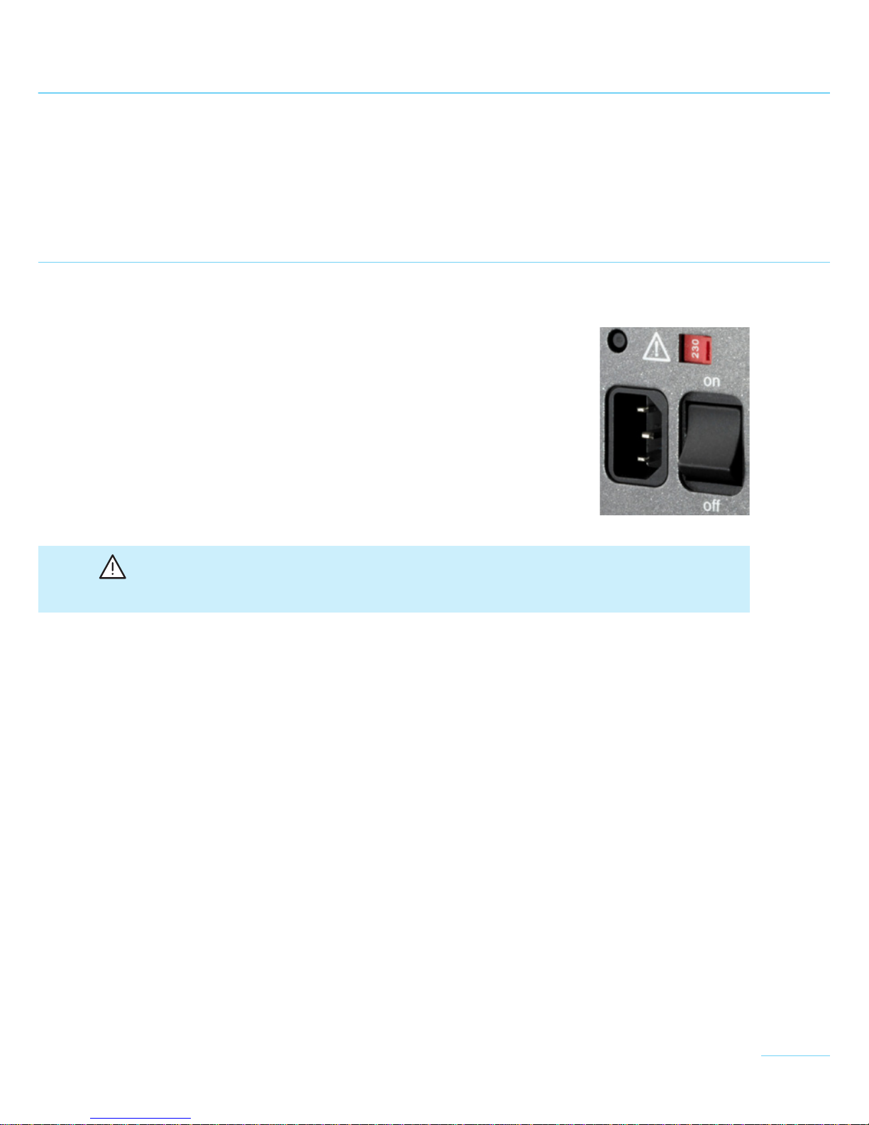
Check that the mains voltage corresponds to the information on the type plate of the unit!
>
The flash light equipment is designed for use in dry conditions and in an ambient temperature
from 0°C to 35°C (32°F to 95°F)! The flash light equipment has to be protected from wetness, con-
densation, from dripping and splash water, humidity, dirt, sand, metal chips and exposure to dust!

7
>
Protect the flash light equipment from electromagnetic fields, shock and vibration!
>
Protect the flash light equipment from heat and frost! If the power pack freezes continuous
loss of power output and serious technical damage can result!
>
Sudden temperature differences can cause condensation water in the unit! In such situations
the equipment must stay for 1 hour in a well-ventilated area to acclimatise to the new tempe-
rature before start up!
>
Do not operate the units in an environment where there is a risk of explosion!
>
The power pack and lamps should not be operated in or near water! Attention: high voltage!
>
The power pack and the lamps should not be immersed in water or other liquids! It could
cause an electric shock!
>
Remove the rubber cap on the front side of the lamp before connecting it to the power pack!
>
For safety reasons, never operate the lamp base without the protecting glass in place! UV-
coated protecting glasses or UV-coated flash tubes must be utilised as a protection against UV
radiation for eyes and skin!
>
Before operation the lamp has to be fastened on a stand or a suspension device! The lamp
must be locked by tightening the mounting screw!
>
Only sand-filled fuses of the type indicated on the fuse type plate may be used! Sand-filled
fuses can be identified by their opaque body! With incorrect fuse protection the halogen lamp
may burst!
>
Filters or diffusers should not be fastened directly on the flash tube, halogen modelling lamp
or protecting glass!
>
Do not operate appliance with a damaged earthed cable. Cables which are damaged or twisted
must be replaced!
>
The unit must only be connected to an earthed socket, or an emergency power generator!
>
If an extension cable is necessary, a cable with a current rating at least equal to that of the
appliance should be used. Cables rated for less amperage than the appliance may overheat.
When using a cable reel, it must be completely unrolled before use to prevent overheating of
the cable!
>
The unit is suitable for operation with a motor generator provided that the voltage lies within
all the load conditions (including capacitive load) and within the tolerance limit of 200-264 V
or 95-135 V! From experience this means that only electronic stabilised motor generators are
to be utilised! When operating on unstabilised motor generators, voltage peaks of 300 V and
more have been observed! This can lead to damages for which we assume no liability!
>
Never operate the unit and lamps inside a bag or a box!
>
The ventilation slots on the unit or on the lamp should not be covered!
>
Pay attention when laying, clearing away or rolling up cables that they do not make contact
with hot surfaces or parts of lamps and that they will not be tripped over by people!
>
Do not touch the connection socket for mains cable and lamp outlets on the power pack and do
not poke inside it with metal objects!

8
>
Flash tubes, halogen modelling lamps and protecting glasses heat up to a high operating tem-
perature, this also applies to the front side of the lamps! Therefore the attachments also assume
high temperatures! Handle with care! Contact with hot components can cause injuries!
>
Do not come into contact with glass or metal whilst operating the flash light system!
>
Let the unit and its connected lamp base cool completely after use and before packing!
>
Always unplug appliance from electrical socket before cleaning, servicing and when not in use!
Never jerk cable to pull the plug from the socket. Grasp plug and pull to disconnect!
>
Dropped or damaged units or lamps must be checked by a specialist before reconnection!
>
To reduce the risk of electric shock, never open the power pack or lamps! Dangerous voltages
could still remain inside the unit even after it has been disconnected from the mains supply. There-
fore, take the unit to an authorised broncolor service station when service or repair work is re-
quired. Incorrect reassembly can cause electric shock, even when the unit is closed.
Shipping instructions Senso A2 / A4:
>
Use original broncolor packing for the transport of the power pack!
Shipping instructions lamps:
>
Use original broncolor packing for the transport of the lamps. Before shipping flash tubes, halo-
gen lamp and protecting glass, pack them with our protective packing material (foam plastic and
transport cap). If the protective packaging is incomplete, remove flash tube, halogen lamp and
protecting glass from the lamp and send them separately!
IMPORTANT SAFETY INSTRUCTIONS

9
1. APPLICATION OF BRONCOLOR SENSO POWER PACK
This mains (AC-line) supplied studio flash unit is designed for professional photography. When
using an extension cable, for your safety, use a three-wire extension cable when possible.
2. START UP
2.1 Mains voltage
As a standard feature, all the Senso power packs are supplied as multi-
voltage units. Ensure that the mains selector switch (19) is set to the
correct voltage.
Senso power packs A2 and A4 supply for operating voltages 100-240 V,
a constant 1200 J or 2400 J.
Attention: Ensure that the operating voltage of the modelling lamp corresponds to the local
mains supply (max. 650 W on 200-240 V or 300 W on 100-120 V). The modelling lamp protection
function (L120) is also available, which is described in detail in section 9.5.
2.2 Earthed mains (AC-line)
Whenever possible, connect unit to current supply always using an earthed mains plug.
2.3 Start up
Use the mains (AC-line) switch (12) to power up the unit. During the charging process, the corres-
ponding digital power distribution display (15 and 17) blinks, after which, it becomes continuous. If
no lamp is connected “----“ appears in the display (15 and 17).

10
3. LAMP OUTLETS
Senso power pack has 3 lamp outlets. The flash
energy is divided between them as follows:
Channel 1 over the lamp outlet with the numerical
14.1
Channel 2 over the lamp outlets with the numerical
14.2 and/or 14.3.
Lamp plugs and sockets have a mechanical locking
device to prevent them from accidentally coming
loose. When plugging in, ensure that the front
part of the plug is inserted first, and that the rear
locking device locks completely into place. To re-
lease, press down the locking device spring under the cable guide and lift out the plug from the
socket. The power pack must be switched off whilst plugging in and unplugging.
Each channel is individually controllable (1 and/or 16 or 2 and/or 18). The digital power distribution
displays (15 and 17) indicate the set energy of each individual channel according to the set mode
(symmetry / asymmetry). In symmetry mode, only the upper digital display (15) is lit, in asymmetry
mode both displays are lit (15 and 17).
4. ENERGY CONTROL
4.1 Introduction
Senso power packs can be set for symmetric or
asymmetric power distribution by actuating the
"sym/asym" rocker switch (3). Power levels can be
differentiated with rocker switches (1 and 2) as
well as with the illuminated silicone keys "q/p" (16
and 18). All setting changes are confirmed with an
acoustic signal. In the symmetric mode, the entire
output energy of 1200/2400 joules (Senso A2/Senso
A4) is available at lamp outlet 14.1, 14.2 or 14.3; if
several lamps are connected, the energy is distri-
buted uniformly to all outputs.
The actuation of rocker switches (1 and 2) allows
unneeded capacitors to be bypassed, which reduces
the energy input level.

11
Attention: When regulating the energy control by means of the rocker switches (1 and 2), the
colour temperature remains constant.
Silicone keys "q/p" (16 and 18) are used for fine
adjustment of the energy. Pressing and holding the
keys will adjust the settings in full f-stops while
short actuations effect changes in 1/10 f-stop inter-
vals. Until the newly selected energy level is attai-
ned by further charging or discharging, the corres-
ponding digital displays (15 and/or 17) will blink
and the "test" key (13) extinguishes. The availability
of the new energy level is annunciated by a beep
(if the buzzer function is enabled) and by the "test"
key (13), which lights up.
4.2 Switchover power display
The output level can be displayed either in f-stops
or energy (joules/watt-seconds). To change the dis-
play mode, press the "test" key (13) for 2 seconds.
4.3 Energy distribution
The Senso distributes power as follows:
Symmetric: >see 4.4
The lamps can be connected to any outlet, power
distribution is symmetric.
Asymmetric: >see 4.5
Lamp outlets 14.1, 14.2, and 14.3 can be used sepa-
rately.
4.4 Examples power distribution in the symmetric
mode
To select the symmetric mode, set the rocker
switch (3) to "sym". The total flash energy is indica-
ted only by the upper display (15); the lower display
(17) is automatically deactivated.
When several lamps are connected, the maximum
total energy is symmetrically distributed to all con-
nected lamps. This means that when two (three)
lamps are connected, half (one third) of the displa-
yed energy is distributed to each lamp.
Attention: In the symmetry mode, power selection is also defined with the two rocker switches
(1) and (2)!

12
The energy distribution with different rocker switch settings is as follows (for the maximum energy
display, the power selector 16 must be set to the highest value):
Examples for 1/1 control via switch (1):
Switch Outlet f-stop value Output
Senso A2
Output
Senso A4
Switch (1) = 1/1
Switch (2) = 1/1
Outlet (14.1)
Outlet (14.2)
Outlet (14.3)
10 1200 joule 2400 joule
Switch (1) = 1/1
Switch (2) = 1/2
Outlet (14.1)
Outlet (14.2)
Outlet (14.3)
9.6 900 joule 1800 joule
Switch (1) = 1/1
Switch (2) = 1/4
Outlet (14.1)
Outlet (14.2)
Outlet (14.3)
9.3 750 joule 1500 joule
Examples for 1/2 control via switch (1):
Switch Outlet f-stop value Output
Senso A2
Output
Senso A4
Switch (1) = 1/2
Switch (2) = 1/2
Outlet (14.1)
Outlet (14.2)
Outlet (14.3)
9.0 600 joule 1200 joule
Switch (1) = 1/2
Switch (2) = 1/4
Outlet (14.1)
Outlet (14.2)
Outlet (14.3)
8.6 450 joule 900 joule
Example for 1/4 control via switch (1):
Switch Outlet f-stop value Output
Senso A2
Output
Senso A4
Switch (1) = 1/4
Switch (2) = 1/4
Outlet (14.1)
Outlet (14.2)
Outlet (14.3)
8.0 300 joule 600 joule
Further reductions can be set in 1/10 or full f-stop intervals with the power selector switches (16).
In the symmetry mode, approx. 106 joules is the lowest possible flash energy level with the Senso
A4 (or 53 joules with the Senso A2). This energy can be further reduced when 2 or 3 lamps are
connected. The lamps can be selectively powered via all three outlets (14.1, 14.2, and 14.3).

13
The energy distribution with different rocker switch settings is as follows (for the maximum energy
display, the power selector keys 16 and 18 must be set to the highest value):
Examples for 1/1 control via switch (1):
Switch Outlet f-stop value Output
Senso A2
Output
Senso A4
Switch (1) = 1/1
Switch (2) = 1/1
Outlet (14.1)
Outlet (14.2)
Outlet (14.3)
9.0
9.0
600 joule
600 joule
1200 joule
1200 joule
or:
Switch (1) = 1/1
Switch (2) = 1/1
Outlet (14.1)
Outlet (14.2)
Outlet (14.3)
9.0
8.0
8.0
600 joule
300 joule
300 joule
1200 joule
600 joule
600 joule
Switch Outlet f-stop value Output
Senso A2
Output
Senso A4
Switch (1) = 1/1
Switch (2) = 1/2
Outlet (14.1)
Outlet (14.2)
Outlet (14.3)
9.0
8.0
600 joule
300 joule
1200 joule
600 joule
or:
Switch (1) = 1/1
Switch (2) = 1/2
Outlet (14.1)
Outlet (14.2)
Outlet (14.3)
9.0
7.0
7.0
600 joule
150 joule
150 joule
1200 joule
300 joule
300 joule
Switch Outlet f-stop value Output
Senso A2
Output
Senso A4
Switch (1) = 1/1
Switch (2) = 1/4
Outlet (14.1)
Outlet (14.2)
Outlet (14.3)
9.0
7.0
600 joule
150 joule
1200 joule
300 joule
or:
Switch (1) = 1/1
Switch (2) = 1/4
Outlet (14.1)
Outlet (14.2)
Outlet (14.3)
9.0
6.0
6.0
600 joule
75 joule
75 joule
1200 joule
150 joule
150 joule
etc. ...
4.5 Examples power distribution in the asymmetric mode
To select the asymmetric mode, set the rocker switch (3) to "asym". The energy levels of both
channels are indicated by displays (15 and 17). In the setting "1/1", each channel delivers at most
half of the possible total energy.
When operating two lamps on channel 2, the energy is equally distributed to both lamp outlets
(14.2 and 14.3).

14
Power selector switches (16 and 18) make it possible to individually reduce the energy level per
channel by up to two further f-stops. When both lamp outlets (14.2 and 14.3) are active, the energy
per lamp on channel 2 can be reduced to 13 joule/26.5 joule (A2/A4).
4.6 Power distribution tables (Senso A2 and A4)
4.6.1 Symmetric mode
(one lamp connected to any lamp outlet)
Channel 1,
rocker switch (1)
on setting
Channel 2,
rocker switch (3)
on setting
Control range
by means of keys
Senso A2 and A4
Power
in joules
Senso A2
Power
in joules
Senso A4
1/1 1/1 8.0 - 10 300 - 1200 600 - 2400
1/1 1/2 7.6 - 9.6 227 - 900 450 - 1820
1/1 1/4 7.3 - 9.3 184 - 750 369 - 1500
1/2 1/2 7.0 - 9.0 150 - 600 300 - 1200
1/2 1/4 6.6 - 8.6 113 - 450 227 - 900
1/4 1/4 5.5 - 8.0 53 - 300 106 - 600
4.6.2 Asymmetric mode
(one lamp per channel)
Channel 1 or 2,
rocker switch (1 or 3)
on setting
Control range
by means of keys
Senso A2 and A4
Power in joules
Senso A2
Power in joules
Senso A4
1/1 7.0 - 9.0 150 - 600 300 - 1200
1/2 6.0 - 8.0 75 - 300 150 - 600
1/4 4.5 - 7.0 26.5 - 150 53 - 300
4.6.3 Asymmetric mode
(2 lamps on channel 2)
Channel 2,
rocker switch (3)
on setting
Control range
by means of keys
Senso A2 and A4
Power in joules
per lamp
Senso A2
Power in joules
per lamp
Senso A4
1/1 7.0 - 9.0 75 - 300 150 - 600
1/2 6.0 - 8.0 37.5 - 150 75 - 300
1/4 4.5 - 7.0 13 - 75 26.5 - 150

15
5. MODELLING LIGHT
The "mod" key (7) switches on the modelling light
for all connected lamps. When switched on, the
blue LED on the right, next to the “mod” key, will
light up. All broncolor lamps have also an additional
modelling lamp switch. Furthermore, it is possible
to operate the modelling light proportionally to the
flash light output.
Attention: Please ensure that the modelling lamp voltage corresponds with the local mains
(AC-line) voltage (100-120 V / 200-240 V)!
Operating modes
The following operating modes are possible:
"full" All lamps with full modelling light, independent of flash output, type of power
pack and power distribution.
"prop" Brightness of the modelling light is automatically proportional to intensity of flash.

16
6. RELEASE
6.1 RFS 2 interface (Radio Frequency System)
Senso power packs are standard-equipped with
a 99-channel RFS 2. Up to 99 devices can be con-
trolled per channel. The antenna is not visible – it
is integrated in the power pack. RFS 2 can be swit-
ched on or off with the "rf" key (4). When RFS 2 is
activated, the blue LED to the right of the "rf" key
will light up. For flash triggering via RFS 2, the
channel of the power pack (studio address) must
correspond to the channel of the RFS 2 transceiver.
The channel (studio address) is defined by pressing
the "aux" key (9) once, followed by the selection of
the channel with the "q/p" keys (16). By pressing
the „aux“ key (9), the actually set studio address (Stxx) appears in display (15), and the unit number
(Unxx) being currently used appears in display (17). The unit number is not relevant for the release
by RFS 2 (see also 9.1).
The channel and unit selection mode can be exited by pressing the "aux" key several times. Alter-
natively, the Senso will automatically return to the ready mode after about 7 seconds.
6.2 Photocell (cell)
The photocell can be switched on or off using the "cell" key (13). If it is activated, the blue LED on
the right, next to the key, lights up.
6.3 Sync socket
The broncolor synchronous cables (art. no. 34.111.00
and 34.112.00) may be plugged into the socket (10)
to trigger flashes via cable.
6.4 "test" key
This key (13) allows manual release of the power
pack. Flash release is possible as soon as 70 % of
the set energy is available.
The visual ready signal (13), however, lights up only
when 100 % is available.

17
7. REMOTE CONTROL
The remote control system has 99 channels (studio addresses) with up to 99 unit addresses per
channel. The channels assign each an independent workstation. Each flash unit within a worksta-
tion is identifiable by its own unit address. Every other workstation can each operate up to 99 flash
units. Therefore, flash units of multiple workstations are clearly identifiable (see also 9.1)
Important: The Senso RFS 2 interface allows remote flash triggering and only limited remote
control of the flash energy, i.e. only power selectors (16 and 18) can be adjusted (by up to 2.5
f-stops). Rocker switches (1 and 2) cannot be remote controlled. The Senso can be configured
in such a way that a warning signal sounds when an energy limit has been reached (see section
9.4).
7.1 Remote control channels (RFS 2 studio address)
Remote control by means of RFS 2 may be performed via separate channels (studio workstations).
These can be set in the power pack (see section 9.). All flash units within a studio workstation must
have the same channel number (studio address).
7.2 RFS 2 unit addresses
Individual unit addresses can be assigned to each power pack (see section 9.). These are used for
individual control of the flash units by means of PC/MAC. This function is not yet available.
8. DISPLAYS VISUAL/AUDIBLE
8.1 The visual ready signal
This is the blue LED at the “test” key (13). It lights
up only when the unit is fully charged or dischar-
ged. After triggering a flash, this LED goes out, and
lights up again when the unit is fully charged once
more. The visual ready signal is easy to read even
in dark rooms due to its bright, blue illumination.
8.2 The audible ready signal
A “beep” tone sounds when 100 % charge is achieved or when the discharge process is finalised.
The signal can be switched on or off.

18
9. ADDITIONAL FUNCTIONS AND SETTING OPTIONS
The "aux" key (9) is used to set the additional functions. Each brief actuation of the key consecu-
tively selects the following operating modes:
• Set studio/unit address > LED "address" blinks
• Slow charge (option for weak mains) > LED „slow“ blinks
• Buzzer / ready tone > LED „buz“ blinks
After the settings have been made, the "aux" key
can be actuated to return to the normal display
mode; this will happen automatically within about
7 seconds.
The respective LED is activated to allow additional
functions to be set. The displays of the two chan-
nels indicate the current settings which can be
changed with the "q/p" keys (16 and/or 18). When
the power pack is switched off and on again, it will
be in the "normal display" mode – additional func-
tion settings are preserved.
9.1 Set studio / unit address
The "address" function allows a studio workstation and an individual unit address to be assigned
to the Senso power pack.
9.1.1 Assignment of studio workstation (St):
The "address" LED is activated with the "aux" key (9). The display of channel 1 (15) indicates the
letters "St" followed by the currently selected studio workstation. A brief actuation of the power
selector keys "q/p" (16) of channel 1 assigns the chosen studio workstation. A longer actuation of
the power selector keys "q/p" (16) changes the setting in tens intervals. Up to 99 workstations can
be assigned ("01 to "99"). All units that need to be triggered from the same camera must have the
same studio number.
9.1.2 Assignment of unit address (Un):
The display of channel 2 (17) indicates the currently selected unit address. A brief actuation of the
power selector keys "q/p" (18) of channel 2 assigns the chosen unit address.
A longer actuation of the power selector keys "q/p" changes the setting in tens intervals. Up to 99
different unit addresses ("01 to "99") can be assigned to each studio workstation.
9.2 Enable/disable slow charging (slo)
The LED “slow” is selected using the „aux“ key (9). The "slow charge" mode can be switched on or
off (on/--) by briefly actuating the power selector keys "q/p" (18) of channel 2. "slow" for longer
charging times is an option for weak mains and motor generators. When the slow charge mode is
selected, the LED next to "slow" will light up.

19
9.3 Enable/disable buzzer / ready tone (buz)
The LED “buz” is selected using the „aux“ key (9). The ready buzzer sounds when the 100% char-
ge is available. The ready buzzer can be switched on or off (on/--) by briefly actuating the power
selector keys "q/p" (18) of channel 2. When the buzzer tone is enabled, the LED next to "buz" will
light up.
9.4 Enable/disable "beep" alarm tone (bEEP)
The alarm tone will sound when an underride/overide of the permissible control range occurs
while adjustments are being attempted. The info index is opened by simultaneously pressing the
"aux" (9) and "mod" (7) keys for 2 seconds. Actuate the keys (16) of channel 1 to select the "bEEP"
option and select either "on" to activate or "--" to deactivate the function using keys (18) of channel
2. Exit the info index by actuating the "aux" key (9).
9.5 Modelling light option "L120"
Senso power packs allow the use of 120 V modelling lamps in 100–230 V regions without having to
exchange the lamps. The info index is opened by simultaneously pressing the "aux" (9) and "mod"
(7) keys for 2 seconds. Actuate the keys (16) of channel 1 to select the "L120" option and select
either "on" to activate or "--" to deactivate the function using keys (18) of channel 2. Exit the info
index by actuating the "aux" key (9).
Note: Switching from 115 V to 230 V with the mains selector switch (19) automatically enables
the L120 function. The protective function allows the use of a 120 V modelling lamp when the
unit is set on 230 V. When changing to a 230 V modelling lamp, it is strongly recommended to
deactivate the L120 protective function.

20
10. PROTECTIVE FACILITIES / FAULT INDICATIONS / ...
10.1 Cooling
The heat dissipated by all key power pack components is constantly monitored by the on-board
processor. This protects the power pack against overheating and optimises its service life. In the
standby mode and if only the modelling light is used, the power pack fan is disabled. It begins to
operate as soon as this becomes necessary after a certain number of flashes have been fired.
10.2 Thermal overheating display
To protect against overheating after extended flash series, the unit will automatically switch off. At
that stage, the following message will appear on the upper LCD display (15): "th" and the approxi-
mate time required for cooling will appear on the lower display. The cooling time is shortened if
the unit remains connected and switched on. Therefore, do not disconnect the unit from the mains
supply.
10.3 Circuit breaker (11)
In the event of an electrical malfunction, the circuit breaker (11) will automatically disconnect the
power pack from the power source. The unit can be restarted by pressing the circuit breaker button.
If it disconnects again immediately the power pack must be serviced by an authorised service
station.
10.4 Overview info and alarm index
Activate the info index by simultaneously pressing the "aux" (9) and "mod" (7) keys for 2 seconds:
Display 1 (15) Display 2 (17)
Pro9 43.00 (example) Software version
BEEP on/-- Alarm “over range” or “under range”
L120 on/-- Modelling light always with 120 V
Cd00 234 (example) Daily flash counter (reset with qkey)
S-nr 1234 (example) Serial number
DatE 1209 (example) Delivery date ex works (mmyy)
C- 00 5234 (example) Flash counter total (cannot be reset)
Exit the info index by pressing the "aux" key (9) for 1 second.

21
Alarm index
Display 1 (15) Display 2 (17) Fault description Measures
A0 U230 Mains selector switch
wrongly set
1. Switch off unit (12)
2. Switch over mains selector switch (19)
3. Switch on unit (12)
A1 Afterglow of flash
tube at end of its
service life
1. Switch off unit (12)
2. Disconnect lamp from power pack
3. Let flash tube cool down
4. Replace flash tube
5. Start up lamp and power pack again
A2 Flash capacitors are
overcharged
1. Switch off unit
2. Wait 1 minute
3. Switch on unit
4. Should the fault occur a second time,
the unit must be checked by a
service station
th 1 Compulsory cooling
phase to protect the
power pack
1. Wait until countdown finishes,
2. The unit is ready for operation
A4 Discharge resistor is
overheating
Please contact your service partner
A5 L1
L2
L3
The flash tube on
lamp L1/L2/L3
has not flashed.
1. Switch off unit
2. Unplug lamp
3. Control flash tube (tightness of
contact, ignition wire on glass) and
eventually replace
4. Plug in lamp and switch on unit
5. Test flashes
6. Should the problem still exist, attempt
steps 1-5 with a new flash tube
7. If the problem cannot be remedied,
please contact your service partner
A6 bAtt Back-up battery for
thermal monitoring
is empty
Please contact your service partner
regarding exchange of back-up battery
A7 Fan does not rotate 1. Switch off unit
2. Please contact your service partner
... DISPLAY INFO

22
11. LAMP COMPATIBILITY
All broncolor lamps are electrically compatible with the Senso power packs. The most popular
lamps, such as the Litos, Pulso and Unilite range, as well as Ringflash (C and P) may be used with
the Senso power packs without any limitations. Increased flash duration for Pulso, Unilite and
Ringflash -> see section 13. Technical data.
Particularly for the small lamps, there are thermal limitations which must be taken into conside-
ration when using them with the Senso power pack (see corresponding max joule / min. on the
lamps).
12. SERVICE/REPAIR
Your broncolor power pack is a precision device, which will work for many years without mal-
function if you take proper care of it. If nevertheless malfunctions do arise, please do not attempt
to open the unit to repair it yourself. Even when the unit is switched off, dangerous voltages may
remain within the interior of the device. Therefore, always let our broncolor service station carry
out repairs or service work.
This manual suits for next models
1
Table of contents