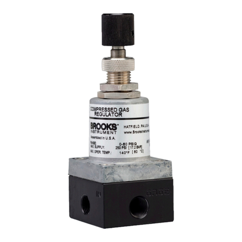
Brooks Instrument GP200 Series User manual

Installation & Operation Manual
GP200 Series Metal Sealed
Pressure-Based Mass Flow Controllers

for local sales office contact information. Save this instruction manual for future reference.
this warning can result in serious personal injury and / or damage to the equipment.
resultinseriouspersonalinjuryand /ordamagetotheequipment.
Connect all products to the proper electrical and pressure sources.
and outlet connections. If no leaks are present, bring the system up to the operating pressure.
maintenance is being performed by qualified persons.
Essential Instructions
Read before proceeding!
European Pressure Equipment Directive (PED)
European Electromagnetic Compatibility (EMC)

Section 1Introduction
Introduction ......................................................................................................................................... 1
How to Use This Manual ..................................................................................................................... 1
Product Support References ............................................................................................................... 2
Notice and Caution Statements .......................................................................................................... 2
Product Warranty ................................................................................................................................ 2
Industry Standard References ............................................................................................................ 2
Glossary of Terms and Acronyms ..................................................................................................... ..3
Product Description ........................................................................................................................... ..4
Specifications for GP200 Series Devices ......................................................................................... ..5
Section 2Installation
General ............................................................................................................................................. 10
Receipt of Equipment ........................................................................................................................ 10
Recommended Storage Practice ...................................................................................................... 10
Return Shipment ............................................................................................................................... 10
Transit Precautions ........................................................................................................................... 11
Removal from Storage ...................................................................................................................... 11
Gas Connections ............................................................................................................................... 11
In-Line Filter ...................................................................................................................................... 11
Mechanical Installation ...................................................................................................................... 11
Flow Controller Installation Arrangement .......................................................................................... 12
Purge the Gas Supply Line Before GP200 Series Installation ..........................................................13
Position and Mount the GP200 Series ............................................................................................ ..14
Perform a Leak Test........................................................................................................................ ..17
Zeroing Setup Process ......................................................................................................................17
Zeroing the GP200 Series from the LCD Display Panel ....................................................................18
Zeroing GP200 Series Over DeviceNet .......................................................................... ..................19
Introduction to the Brooks Expert Support Tool .............................................................................. ...20
Using the Brooks Expert Support Tool ............................................................................ ...................21
GP200 Alarms in the Brooks Expert Support Tool ......................................................... ...................22
GP200 Warping in the Brooks Expert Support Tool ....................................................... .................24
Electrical Connections....................................................................................................................... .25
EtherCAT Connections ...................................................................................................................... 25
DeviceNet Connections......................................................................................................................26
Analog/RS485 Connections ............................................................................................................... 27
Section 3Operation
General ............................................................................................................................................. .29
Theory of Operation for Pressure-Based Flow Measurement ............................................................29
Section 4Maintenance & Troubleshooting
Maintenance & Troubleshooting Overview .........................................................................................32
Maintenance ........................................................................................................................................32
Troubleshooting ..................................................................................................................................33
Troubleshooting Checklist ...................................................................................................................33
GP200 Series Troubleshooting Guide ................................................................................................34
Section 5Product Description Code
Overview .............................................................................................................................................38
Section 6Appendix
Appendix A: GP200 Series Patents .................................................................................................. ..40
Contents
GP200 Series
Performance Checks...........................................................................................................................20
GP200 Gas Pages in the Brooks Expert Support Tool ......................................................... .............22

GP200 Series
Figure 1-1 Dimensions of GP200 Series Downport Configurations ................................................... 8
Figure 1-2 Dimensions of GP200 Series VCR Configurations ........................................................... 9
Figure 2-1 Typical Gas Supply Arrangement .................................................................................... 13
Figure 2-2 GP200 Series Mounting Attitude Positions ...................................................................... 15
Figure 2-3 GP200 Series Mounted to K1 Series Substrate Blocks .................................................... 16
Figure 2-4 Mounting Screws Torque Pattern ..................................................................................... 16
Figure 2-5 GP200 Display showing "%FS" ........................................................................................ 18
Figure 2-6 Top View of GP200 Series Device ................................................................................... 19
Figure 2-7 DeviceNet Remote Diagnostic Example .......................................................................... 20
Figure 2-8 Standard USB to Micro USB Cable .................................................................................. 21
Figure 2-9 GP200 Series Alarm Status Window in BEST .................................................................. 22
Figure 2-10 GP200 Series Alarm Settings Window in BEST ............................................................. 23
Figure 2-12 GP200 Warping in the Brooks Expert Support Tool ....................................................... 25
Figure 2-13 GP200 Series EtherCAT M8 Power Connector .............................................................. 26
Figure 2-14 EtherCAT Power Connector Drawing ............................................................................. 26
Figure 2-15 GP200 Series DeviceNet Connection ............................................................................ 27
Figure 2-16 DeviceNet Pin Connections ........................................................................................... 27
Figure 2-17 GP200 Series Analog 9-Pin Connector .......................................................................... 28
Figure 2-18 GP200 Series Analog 9-Pin Connector (M) .................................................................... 28
Figure 3-1 GP200 Series MFC Architecture ...................................................................................... 30
Figure 3-2 Hagen-Poiseuille Equation ............................................................................................... 30
Figure 3-3 GP200 DP Measurement Concept ................................................................................... 31
Tables
Table 1-1 Industry Standard References .......................................................................................... 2
Table 1-2 Terms and Acronyms ........................................................................................................ 3
Table 1-3 Specifications for GP200 Series ........................................................................................ 6
Table 2-1 K1 Series Fasteners ......................................................................................................... 16
Table 2-2 K1 Substrate Torque Data ................................................................................................ 16
Table 4-1 Environmental Factors ...................................................................................................... 34
Table 4-2 GP200 Series Troubleshooting Guide ............................................................................... 34
Table 5-1 GP200 Series Model Code ............................................................................................... 38
Contents
Figures
Figure 2-11 Changing Gas Pages using BEST..................... ............................................................. 24

Introduction
The GP200 Series is the first fully (both inlet and outlet) pressure
insensitive P-MFC, designed specifically for semiconductor
applications. The GP200’s unique differential pressure technology,
coupled with its downstream valve architecture, removes the
current limitations of pressure-based mass flow controllers,
enabling the most precise process gas delivery over the widest
range of operating conditions in the industry.
As the inventor and market leader in gas and flow range
programmable Mass Flow Controllers, Brooks sophisticated and
proprietary MultiFlo™ gas model is now embedded within each
GP200 device enabling on-the-fly gas & range reconfiguration for
maximum process flexibility.
The GP200’s ultra-fast, highly repeatable Matched Transient
Response and dynamic cross-talk insensitivity enable tighter
process control, handling extreme supply pressure variations while
maintaining precise mass flow control to the chamber. The GP200
platform supports a broad range of process conditions which
enables drop-in replacement and upgrade of many traditional
pressure-based mass flow controllers.
How toUse This Manual
This manual is intended to provide the user with all the information
necessary to install, operate, troubleshoot, and maintain these
pressure-based mass flow devices. The manual is organized in the
following sections:
•Section 1 Introduction
•Section 2 Installation
•Section 3 Operation
•Section 4 Maintenance and Troubleshooting
•Section 5 Product Description Code
•Section 6 Appendix
It is recommended that this manual be read in its entirety before
attempting to operate or repair these devices.
Section 1 Introduction
1

Product Support References
Refer to www.BrooksInstrument.com for Brooks sales and service
locations and to obtain other documents that support the GP200
Series. Those documents include:
•Brooks Expert Support Tool (BEST)
•Brooks GP200 Series Datasheet
Notice and Caution Statements
Warning, caution, and notice statements are located throughout this
manual in the ANSI format. A WARNING statement indicates a
potentially hazardous situation which, if not avoided, COULD result
in death or serious injury. A CAUTION statement indicates a
potentially hazardous situation which, if not avoided, MAY result in
minor or moderate injury. It may also be used to alert against unsafe
practices. A NOTICE statement describes specific information that
requires special attention.
Product Warranty
Product warranty information can be found on the Brooks website
at www.BrooksInstrument.com. This information provides general
warranty information, limitations, disclaimers, and applicable
warranty periods according to product group.
Industry Standard References
Table 1-1 Industry Standard References
Reference Number
Reference Description
MIL-STD-810
Method 514.4, Category 1, Transportation Requirement
Method 516.4, Procedure 1, Functional Shock Test Requirement
SEMI E12
Standard temperature and pressure
SEMI E16
Guideline for determining and describing MFC leak rates
SEMI E17
Guideline for MFC transient characteristics tests
SEMI E18
Guideline for temperature specifications of the MFC
SEMI E27
Standard for MFC and MFM linearity
SEMI E28
Guideline for pressure specifications for the MFC
SEMI E52
Practice for referencing gases used in digital MFCs
SEMI E54
Sensor actuator network connections for DeviceNet
SEMI E56
Test method for determining accuracy, linearity, repeatability, short-term
reproducibility, hystereses of thermal MFCs
SEMI E66
Test method for determining particle contribution by MFCs
SEMI E67
Test method for determining reliability of MFCs
SEMI E68
Test method for determining warm-up time of MFCs
Section 1 Introduction
2

SEMI E69
Test method for reproducibility and zero drift for thermal MFCs
SEMI E80
Test method for determining attitude sensitivity of MFCs
SEMI E16-90
Guidelines for determining and describing mass flow controllers leak rates
SEMI F19
Specification for the finish of the wetted surface of electro polished
216L stainless steel components
SEMI F20
Specifications for 316L stainless steel bar, extruded shapes, plate, and
investment castings for components used in ultra-high purity semi
manufacturing applications
SEMI F36
Guide for dimensions and connections of gas distribution components
SEMI F37
Method for determination of surface roughness parameters for gas
distribution system components
SEMI F44
Guideline for standardization of machined stainless steel weld fittings
SEMI F45
Guideline for standardization of machined stainless steel reducing fittings
SEMI F47
Specifications for semiconductor processing equipment
voltage sag immunity
SEMI S2
Environmental, Health and Safety Guidelines
SEMI S9
Dielectric testing
SEMI S10
Risk assessment
SEMI S12
Decontamination of fielded products
ETG.1000.2
Physical Layer service definition and protocol specification
ETG.1000.3
Data Link Layer service definition
ETG.1000.4
Data Link Layer protocol specification
ETG.1000.5
Application Layer service definition
ETG.1000.6
Application layer protocol specification
ETG.1020
EtherCAT Protocol Enhancements
ETG.2000
EtherCAT Slave Information
ETG.5001.1
Modular Device Profile - Part 1: General MDP Device Model
ETG.5003.1
Semiconductor Device profile - Part 1: Common Device Profile (CDP)
ETG.5003.2020
Specific Device Profile: Enhanced Mass Flow Controller
ETG.5003.2021
Specific Device Profile: Mass Flow Controller
ETG.5003.2022
Specific Device Profile: Mass Flow Meter
ETG.5003.2023
Specific Device Profile: Enhanced Mass Flow Meter
Glossary of Terms and Acronyms
Table 1-2 Terms and Acronyms
Term or Acronym
Definition
CSR
Customer Special Requirement
CVD Chemical Vapor Deposition
DeviceNet
A 5-wire local network I/O communication device that employs a command/response
communication protocol
DSP Digital Signal Processor
EPI Epitaxy (EPI)
A process technology where a pure silicon crystalline structure is deposited or “grown”
on a bare wafer, enabling a high-purity starting point for building the semiconductor
device.
HBD
Horizontal Base Down
GP200 Series
Pressure Based Mass Flow Controller
Section 1 Introduction
3

F.S.
Full Scale
LED
Light Emitting Diode
MFC
Mass Flow Controller
MultiFlo Technology
A physics-based calibration methodology that enables gas and flow range
configuration within a defined standard configuration
P-MFC Pressure-Based Mass Flow Controller
PID Proportional Integral Derivative Controller
PSIA
Pounds per Square Inch Absolute
PSID
Pounds per Square Inch Differential
PSIG
Pounds per Square Inch Gauge
PTI
Pressure Transient Insensitive. Reduces the effect of pressure fluctuations in gas flow.
ROR
As pressure increases, flow increases at a pressure rate of rise, or ROR.
S.P.
Setpoint
VIU
Vertical mounting attitude with inlet side facing up
Product Description
The GP200 Series is the first fully (both inlet and outlet) pressure
insensitive P-MFC, designed specifically for semiconductor
applications. The GP200’s unique differential pressure technology,
coupled with its downstream valve architecture, removes the
current limitations of pressure-based mass flow controllers,
enabling the most precise process gas delivery over the widest
range of operating conditions in the industry.
As the inventor and market leader in gas and flow range
programmable Mass Flow Controllers, Brooks sophisticated and
proprietary MultiFlo™ gas model is now embedded within each
GP200 device enabling on-the-fly gas & range reconfiguration for
maximum process flexibility.
The GP200’s ultra-fast, highly repeatable Matched Transient
Response and dynamic cross-talk insensitivity enable tighter
process control, handling extreme supply pressure variations while
maintaining precise mass flow control to the chamber. The GP200
platform supports a broad range of process conditions which
enables drop-in replacement and upgrade of many traditional
pressure-based mass flow controllers.
True Differential Pressure Measurement
By removing the requirement to match and compensate two
Section 1 Introduction
4

separate pressure transducers, the GP200 differential pressure
technology reduces measurement uncertainty for enhanced
accuracy, repeatability, and drift performance.
Lower Inlet Pressure Operation
Safer fab operation at lower inlet pressures is now achievable with
a P-MFC due to the GP200’s differential pressure sensor that is
specifically optimized for low differential pressure measurement.
Cross-Talk Insensitive
Maintains tight process control under dynamic process conditions-
the accuracy of the GP200 P-MFC will stay within ≤ ± 1% of S.P.
during extreme pressure supply disruptions up to 40 psi/sec.
Matched Transient Response
Ultra-fast, highly repeatable ascending and descending flow
stabilization time enables tighter process control in advanced high
cycle Deposition and Etch processes.
Downstream Valve Architecture
The GP200's downstream valve architecture ensures that accuracy
is independent of downstream pressure, enabling flow delivery into
pressures as high as 1200 Torr. The GP200's fast closing valve
addresses non-productive recipe wait times, or "tail effects", that
are seen in upstream MFC valve designs that require additional
time to bleed down their internal volume of gas.
Zero Leak-by Control Valve
100X improvement in valve shut-down addresses the long standing
“first wafer effect” where the accumulation of unmetered gas
(between the MFC control valve & downstream isolation valve)
contributes to non-uniformities and Critical Dimension (CD) defects
on the first wafer of a process.
High Flow Rate Capability
10 sccm to 50 slm F.S. N2 equivalent P-MFC supports all process
flow needs with just nine (9) standard bin configurations for
maximum flexibility.
Specifications for GP200 Series Devices
Section 1 Introduction
5

Table 1-3 Specifications for GP200 Series
Section 1 Introduction
6

Section 1 Introduction
7

Figure 1-1 Dimensions of GP200 Series Downport Configurations
Section 1 Introduction
8

Figure 1-2 Dimensions of GP200 Series VCR Configurations
Section 1 Introduction
9

General
This section provides installation instructions for the Brooks GP200
Series Pressure-Based Mass Flow Devices. The installation
process consists of purging the gas supply line prior to installation,
unpacking, inspecting the device, connecting the device to the gas
supply line, and testing for leaks.
Receipt of Equipment
When the equipment is received, the outside packing case should
be checked for damage incurred during shipment. If the packing
case is damaged, the local carrier should be notified at once
regarding his liability. A report should be submitted to the nearest
Brooks Instrument location listed on the Global Service Network
page on our website:
BrooksInstrument.com/GlobalSupportCenters
This device has been assembled, calibrated, and double-vacuum
bagged in a Class 100 clean room. In your semi-clean area, remove
the outer bag only. Pass the device into your clean area. Remove
the second clean room compatible bag only when the device is
ready to be tested and/or installed in your clean system.
Recommended Storage Practice
If intermediate or long-term storage of the device is required, it is
recommended that it be stored in accordance with the following
conditions:
•Within the original shipping container.
•Ambient temperature 21°C (70°F) nominal, 32°C (90°F)
maximum, 7°C (45°F) minimum.
•Relative humidity 45% nominal, 60% maximum, 25%
minimum.
Return Shipment
Prior to returning any instrument to the factory for any reason, visit
our website for instructions on how to obtain a Return Materials
Authorization Number (RMA #) and complete a Decontamination
Statement to accompany it:
BrooksInstrument.com/Service
All instruments returned to Brooks also require a Safety Data Sheet
Section 2 Installation
10

(SDS) for the fluid(s) used in the instrument. Failure to provide this
information will delay processing of the instrument. Instrument must
have been purged in accordance with the following:
Transit Precautions
To safeguard against damage during transit, transport the device to
the installation site in the same container used for transportation
from the factory, if circumstances permit.
Removal from Storage
Upon removal of the device from storage, a visual inspection should
be conducted to verify its "as-received" condition. If the device has
been subject to storage conditions more than those recommended
(refer to "Recommended Storage Practice"), it should be subjected
to a pneumatic pressure test in accordance with applicable vessel
codes. To maintain a device’s ultra-clean integrity, this service
should be performed by the factory or one of the certified service
centers.
Gas Connections
Prior to installation, ensure that all piping is clean and free from
obstructions. Install piping in such a manner that permits easy
access to the device if removal becomes necessary.
In-Line Filter
It is recommended that an in-line filter be installed upstream from
the device to prevent the possibility of any foreign material entering
the flow sensor or control valve. The filtering element should be
replaced periodically or ultrasonically cleaned.
Mechanical Installation
Section 2 Installation
11

The recommended installation procedure guidelines are as follows:
•The device should be in a clean, dry atmosphere relatively
free from shock and vibration.
•Leave sufficient room for access to the user interface,
display and MAC ID and baud rate switches (if equipped) at
the top of the device.
•Install the device in such a manner that permits easy purge
and removal if the device requires servicing.
Flow Controller Installation Arrangement
Typical gas supply arrangements are shown below. GP200s are
often arranged inside a gas panel. With the gas model now
embedded in each GP200 device, on-the-fly gas & range
reconfiguration is made possible for maximum process flexibility.
The GP200 P-MFC can be reconfigured for a variety of pure gases
and mixtures, enabling the user to reduce unique inventory
requirements.
Section 2 Installation
12

Figure 2-1 Typical Gas Supply Arrangement
Purge the Gas Supply Line Before GP200 Series Installation
Before operating the GP200 Series, the gas supply line must be
completely purged with nitrogen or argon to ensure the line is free
from toxic or flammable gases, contaminants, moisture, and
oxygen. The purge gas must be free of moisture and oxygen to less
than 100 ppb. Purge the gas lines as follows or in accordance to
prescribed company and safety procedures.
1. Shut off the process gas supply valve(s) upstream of the GP200
For additional safety, it is recommended to close the two valves between
the charged gas line and the GP200 Series to be installed. See Figure
above for more details.
It is recommended to archive service and calibration documentation for
the GP200 Series to determine the contamination state of each gas line
and to assist service personnel.
DO NOT remove the shipping caps covering the inlet/outlet for VCR
fittings, or DO NOT remove the blue tape on the bottom of the device for
downport fittings before the GP200 Series is being installed. Failure to
comply will introduce contaminants into the GP200 Series.
Section 2 Installation
13

Series. If such a valve is not available, shut the valve on the gas
panel. Tag the valve at this point to prevent accidental re-
exposure of the process gas to the gas line.
2. Cycle purge the gas line with dry nitrogen or argon to fully flush
out the process gas. Cycle purging consists of evacuating to a
low pressure adequate to induce out-gassing and then purging
to remove adhered moisture and oxygen. If a toxic or reactive
gas is present and a clogged GP200 Series is suspected, then
proceed with caution. Pump down and purge the GP200 Series
from both downstream and upstream lines. If check valves are
present in the gas line, both pumping down and purging are
required. Pumping down without purging is inadequate. If a
good vacuum source is not available, the GP200 Series can be
de- contaminated by purge only.
3. Repeat the purge cycle several times within 2-4 hours to
complete the cleaning. For toxic and corrosive gasses, it is
recommended to use 100-120 cycles.
Position and Mount the GP200 Series
Position the GP200 Series so that the gas flow is pointed in the
same direction as the flow arrow shown on the GP200 Series rear
label and outer can. The various mounting positions are described
in the figure below.
The standard orientation for the GP200 Series is Horizontal Base
Down (HBD). The accelerometer in the GP200 automatically
determines the orientation of the device and proprietary algorithms
compensate for any potential orientation effects. It is recommended
that the MFC is re-zeroed with process gas following the
recommended Brooks procedure after a change in device mounting
orientation.
Section 2 Installation
14

Figure 2-2 GP200 Series Mounting Attitude Positions
If your GP200 Series is configured with downport fittings, follow
Steps 1 through 4 below. If your GP200 Series has VCR fittings,
proceed to Step 5.
1. Refer to Figure 2-3 GP200 Series Mounted to K1 Series
Substrate BlocksFigure 2-3 below. If downported fittings (1) are
used, the GP200 Series is mounted to K1 Series substrate
blocks (2) with four screws (3). Metal C-seals or W-seals (4) (as
provided by integrator) are inserted between the GP200 Series
and substrate blocks before the screws are installed. These
metal seals must be replaced after each installation.
2. Select the mounting screws noted in Table 2-1 for downported
devices. M4 screws are used on 1.125" devices, K1S. M5
screws are used on 1.5" devices, K1R2 and K1H.
3. Refer to Figure 2-3. Insert the two mounting seals (4) over the
gas flow path of the K1 block. Carefully align the GP200 Series
mounting holes onto the K1 substrate blocks. Using your
fingers, install the screws through the GP200 Series fitting and
hand tighten.
Section 2 Installation
15

Figure 2-3 GP200 Series Mounted to K1 Series Substrate Blocks
Figure 2-4 Mounting Screws Torque Pattern
Table 2-1 K1 Series Fasteners
Connection
Fastener Size
K1S
K1R2
K1H
GP200 to
Substrate
M4 x 34mm
or
M4 x 35mm
M5 x 30mm
M5 x 37mm
Table 2-2 K1 Substrate Torque Data
Connection
Torque Pattern
Torque (Inch-Pounds)
GP200 to
Substrate
Use a square pattern as
shown in Figure 2-5.
Start at 25 inch-pounds and
increase in increments of
10 inch-pounds until proper
value is obtained.
K1S
K1R2
K1H
45 45 45
4. Using a torque wrench and a metric hex key, tighten the
screws to the torque value as described in Table 2-2 and
Torque Pattern Figure 2-4.
Section 2 Installation
16
Table of contents
Other Brooks Instrument Controllers manuals
Popular Controllers manuals by other brands

Daikin
Daikin ECFWEB6 Installation and operation manual

Furious FPV
Furious FPV RACEWHOOP Manual user instructions

Toshiba
Toshiba LC531 Series instruction manual

Happy
Happy NG 1.1 Operating instruction

Turtle Tough
Turtle Tough PD8-6080-6H0-TU instruction manual

Mi-Light
Mi-Light MiBoxer FUT039SA user manual