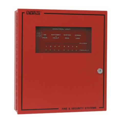
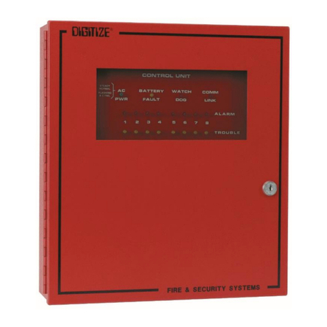
DIGITIZE System 3000 User manual

(STATUS)
TEST
MODE
BATT
(REPORT)
LAMP
PRINT
SYSTEM 3000N
ADVANCE
PAPER
ON
K
C
A
OFF
OUT OF SERVICE
SECURE
TROUBLE
S1
SERVICE
IN/OUT
ADV
ACK LP
XMIT
NIGHT SLOW
SET LOG
LOG
DAY/
STOP
XMIT
ALARM
2
5
8
0
4
7
CLEAR
D
1
A
6
9
-
EF
FUNC
SET
3
BC
OFF
ON
LOOK UP
BOX ZONE
LOOK UP
DIALER
LOOK UP
R
R
SYSTEM3000
INSTALLATIONandOPERATION
MANUAL

TRADEMARKS
DIGITIZE (stylized) is a registed trademark of Digitize, Inc.
First ... When Seconds Count.
Firestar
ISOdressable
CGRMS
All of the above are trademarks of Digitize, Inc.
FC-ID is a trademark of Fire Control Instrument Co.
Caution: For this manual to be valid you must have the SYSTEM 3000 Software Revision Level 6.0.0
or higher.
Digitize, Inc.
158 Edison Road
Lake Hopatcong, New Jersey 07849
Tel: (973) 663-1011
FAX: (973) 663-4333
Part Number 700181
Issue Revision: E
Issue Date: 7/95

PROPRIETARY NOTICE
AND DISCLAIMER
DIGITIZE, INC.
158 EDISON ROAD
LAKE HOPATCONG, NJ 07849
(973) 663-1011
FAX: (973) 663-4333
This manual has been prepared by DIGITIZE, INC. for use by its licensees, dis-
tributors and customers. The information contained herein is the property of DIGI-
TIZE, INC. and may not be copied, disclosed or reproduced, in whole or in part,
withoutthepriorwritten approvalof DIGITIZE,INC. Anyunauthorizeddisclosureto,
or use of the enclosed information by, unauthorized third persons shall void any
and all representations, warranties and obligations on the part of DIGITIZE, INC.
DIGITIZE,INC.reservestherighttomakechangestothespecificationsandmate-
rial contained herein without prior notice. The information and/or
examples (including, but not limited to circuitry, wiring diagrams, programming,
the operation or use shown) described in this manual are intended solely to illus-
trate the operating principles of the particular product. They are not a warranty,
representation or guarantee that a particular example or use shown will perform in
a particular situation. They are given for illustration purposes only. DIGITIZE, INC.
shall not be responsible, nor does it represent, that any example of illustration will
perform in a particular environment or practice unless it specifically makes a rep-
resentation to that effect.
The material set forth herein is for informational purposes only, and
DIGITIZE, INC. assumes no patent liability with respect to any information or illus-
trations contained herein.
PROPRIE.CHP REV.B

FCC NOTICE
In compliance with Paragraph 15.105 of the FCC Rules and Regulations, the following notice
is provided:
NOTE: This equipment has been tested and found to comply with the limits for a Class A
digital device, pursuant to Part 15 of the FCC Rules. These limits are designed to provide
reasonable protection against harmful interference when the equipment is operated in a
commercial environment. This equipment generates, uses, and can radiate radio frequency
energy, and if not installed and used in accordance with the instruction manual, may cause
interference to radio communications. Operation of this equipment in a residential area is
likely to cause harmful interference in which case the user will be required to correct the
interference at his own expense.
P/N 770120 Rev. C

iii
4.5.5. SERIALPORTCOMMUNICATIONS...........................................................................4-17
4.5.6. MULTIPLEX SET-UP ..................................................................................................4-18
4.5.6.1. ADD/CHG/DEL .............................................................................................4-18
4.5.6.2. LINE TYPE SEL ............................................................................................4-19
4.5.6.3. POLLING RATE ............................................................................................4-19
4.5.7. NETWORK SETUP ......................................................................................................4-19
4.5.8.1. CHANGING LEVEL DESCRIPTORS.............................................................4-20
4.5.8. IN/OUT SERVICE PASSWORD YES/NO .....................................................................4-20
4.5.8.2. IN/OUT SERVICE PASSWORD .....................................................................4-21
4.5.9. SOLID-STATE TELEGRAPHIC TRANSMITTER.........................................................4-21
4.5.10. SPEED TRANSLATOR FOR SOLID STATE TELEGRAPHIC TRANSMITTER............4-22
4.5.11. RADIO BOX SET-UP ...................................................................................................4-23
4.6. NEGATIVE BOX/DIALER .......................................................................................................4-24
4.6.1. OVERVIEW .................................................................................................................4-24
4.6.2. ENTERING NEGATIVE DIALER/RADIO BOX............................................................4-24
4.6.3. ISODRESSABLE SET UP MODE.................................................................................4-25
4.6.4. DAY/NIGHT SET UP MODE........................................................................................4-25
4.7. ADDRESSABLE LINE PRINTERS ..........................................................................................4-26
4.7.1. OVERVIEW .................................................................................................................4-26
4.7.2. ADDRESSABLE PRINTER SET UP MODE .................................................................4-27
4.7.3. SUPERVISION .............................................................................................................4-27
SECTION 5 OPERATION
5.1. CONTROLS ...............................................................................................................................5-1
5.1.1. PAPERADVANCE .........................................................................................................5-1
5.1.2. PRINT............................................................................................................................5-1
5.1.3. LAMP TEST ..................................................................................................................5-1
5.1.4. BOX LOOK UP ..............................................................................................................5-2
5.1.5. DIALERLOOKUP ........................................................................................................5-2
5.1.6. ZONE LOOK UP ............................................................................................................5-2
5.1.7. NUMERIC KEYS ...........................................................................................................5-3
5.1.8. CLEAR BUTTON...........................................................................................................5-3
5.1.9. HYPHEN BUTTON ........................................................................................................5-3
5.1.10. FUNC BUTTON .............................................................................................................5-3
5.1.11. SET BUTTON ................................................................................................................5-3
5.1.12. ON / ↑ BUTTON ..........................................................................................................5-3
5.1.13. OFF/ ↓BUTTON..........................................................................................................5-4
5.1.14. ACK BUTTON ...............................................................................................................5-4
5.1.15. IN/OUT SERVICE ..........................................................................................................5-4
5.1.16. XMIT BUTTON .............................................................................................................5-5
5.1.17. XMIT SLOW..................................................................................................................5-5

1 - 1
DIGITIZE, INC. 700181-E
SYSTEM 3000 INSTALLATION AND OPERATION MANUAL
SECTION 1
GENERAL INFORMATION
This manual provides the basic installation and operating procedures and instructions for the DIGITIZE
SYSTEM3000. Illustrationsareprovided throughout tofamiliarizetheoperatorwith the terminologyused
inthismanual. Operatorsandinstallersareadvisedtostudytheillustrationsandsystemdescriptionsbefore
reading the operating procedures. All installation and testing should be performed by factory trained
personnel.
1.1.SYSTEM DESCRIPTION
Theoverall systemis knownas theDIGITIZE AlarmProcessing System. Alarmsare processed
from alarm/control sensors through alarm/control lines. When an alarm/control condition occurs,
an audible alarm, indicator lamp, alphanumeric message display, and a printed hard copy record
of the alarm/control condition will be presented to the operating personnel. The system may be
comprisedofsingleormultipleSYSTEM3000’sand/orComputerGraphicResponseManagement
Systems. The system is designed for fire alarm reporting, security alarm monitoring and control
applications for the municipal, industrial, military, collegiate, and commercial sectors.
1.2. SYSTEM 3000
TheoverallunitisknownastheSYSTEM3000. TheSYSTEM3000isatotallysolidstatesystem
that uses state of the art devices and circuitry to continuously monitor and display the status of all
system connected alarms. The SYSTEM 3000 is a microprocessor-based alarm monitoring and
control unit, with field programmable, nonvolatile memory. The SYSTEM 3000 may be used to
monitor multiplex, telegraph/McCulloh code, direct wire, digital dialer, network, addressable,
polling radio, and serial input alarm signals. The SYSTEM 3000 will also provide an alarm (both
visual and/or audible) to operating personnel in the event of an internal SYSTEM 3000
malfunction. The basic unit is supplied with the following standard equipment:
lPrinted circuit boards: POWER, DISP/KEY, CPU VI, E2PROM, PRT/KB, and I/O.
l150 Pages of field programmable memory for input of user text information.
lIntegral 20 column thermal printer capable of half, standard, and double height printing
in normal or bold intensity.
lFront panel mounted, 64 character, “plasma” type display readable at distances up to 15
feet.
lComputer style keyboard for user text entry as well as system setup.

DIGITIZE, INC. 700181-E
1 - 2
SYSTEM 3000 INSTALLATION AND OPERATION MANUAL
1.3 ALARM TYPES
The SYSTEM 3000 handles three alarm type categories: ZONE, DIALER, and BOX. The
categories can be further broken down as follows:
ZONE •Direct wire inputs via EOL, RPI, or DCI input cards.
•Multiplex inputs via Data Gathering Panels including serial devices connected
to fire alarm panels.
•Polling radio zones via Radio Data Gathering Panels.
•Addressable devices such as Infrared detectors, magnetic door contacts via
the ISOdressablecapability, etc.
DIALER •Dialers monitored via DIGITIZE Digital Dialer receiver cards.
BOX •TELEGRAPH/McCULLOHcodedboxes.
Throughout this manual, when the terms ZONE, DIALER, or BOX are used, unless otherwise
indicated, they refer to any of the above devices.
1.4.MEMORY
EachSYSTEM3000issuppliedwith150screensofnonvolatile,nonmagnetic,fieldprogrammable
memory for storage of user text information. This memory is located in the “system” memory
moduleandoccupiesthefirstI.C.socket,(U1)ofthefirstmemorymotherboard,whichisprovided
with the system. All memory module data will be maintained in the event of a complete power
failure,includingthelossofbatterybackup. There are seven (7) empty memorysocketsavailable
onthe systemsupplied memory motherboard. Nonvolatile, nonmagnetic storagemay beadded to
the SYSTEM 3000 by installing memory modules and additional motherboards. Each of these is
explained below.
1.4.1.MEM-600MEMORYCHIP
MEM-600 MEMORY CHIP P/N 450423-0002
INSTALLATIONSHEET P/N 800250, sheet #3
Each MEM-600 provides storage for up to 600 screens of field programmable user text
messages, each screen consisting of 3 lines of 16 characters each. Each direct wire zone,
multiplex zone, digital dialer account or telegraph box can have up to 9 screens of memory
assigned to it.

1 - 3
DIGITIZE, INC. 700181-E
SYSTEM 3000 INSTALLATION AND OPERATION MANUAL
1.4.2.MBD-4800MEMORYMOTHERBOARD
MBD-4800, Full Memory Board P/N 400349-0004
MBD-EMPTY, Empty Memory Board P/N 400349-0002
EachMBD-EMPTYprovidesspaceforupto8MEM-600memorymodules,oratotalof4800
screens. The MBD-4800 contains all 4800 screens, and is installed in any of the card slots of
theSYSTEM 3000. EachMBD-4800 hasa DIPswitch toallow youto setthe addressof the
board. A total of eight motherboards may be installed in one system. The number is limited
only by the number of available card slots. A fully loaded system can allow access to 37,950
field programmable user text screens.
1.5.SPECIFICATIONS
1.5.1. ELECTRICAL
Primary A.C.:
PowerInput ........................................ 103-127 VAC / 207-253 VAC
Frequency Input .................................. 47-63 Hertz
Power Consumption............................. 50 Watts (max)
Standby D.C.:
PowerInput ........................................ 24 VDC (nom)
Operating Current ............................... 1 Ampere DC (max)
1.5.2. FUSES
A.C. line input fuse.................................... 3.0 Amp. (fast-blow)
D.C. circuit breaker ................................... 5.0 Amp.
1.5.3. INPUTS
ACPower ................................................. DetachableCord
Standby Battery......................................... 24 Volts D.C.
TERMINALS: Option Terminals 1 through 4 are used for the single circuit “Telegraph
Coded Input” option.
INPUTS 1-3: Configured by options installed.

DIGITIZE, INC. 700181-E
1 - 4
SYSTEM 3000 INSTALLATION AND OPERATION MANUAL
1.5.4.OUTPUTS
EXT. BUZZ: 12 Volt D.C., 0.1 A output for an external system failure buzzer.
AUDIOOUT: “Line” level output, (1 Volt P-P) identical to that of the front panel
speaker for connection to an external amplifier or P.A. system.
SST FAST: Normallyopenandnormallyclosed“dry”relaycontactsusedforspecial
options.
SST SLOW: Normallyopenandnormallyclosed“dry”relaycontactsusedforspecial
options.
OUTPUTS 1-3: Configured by options installed.
1.5.5.CONSTRUCTION
The enclosure and cover of the SYSTEM 3000 is made of 0.062" aluminum. A membrane
keypad is mounted on a 0.093" aluminum front panel.
1.5.6.DIMENSIONS
Height ................................................ 6.97" (17.7 cm)
Width ................................................. 19.0" (48.3 cm)
Depth ................................................. 15.5" (39.5 cm)
1.5.7. WEIGHT
Net Weight ......................................... 21.3 lb. (9.7 Kg)
Shipping Weight.................................. 25.0 lb. (11.38 Kg)
1.5.8.TEMPERATUREANDHUMIDITY
The SYSTEM 3000 operates best in an environment that is controlled for the comfort of
operating personnel, with respect to levels of temperature, humidity, and dust content. The
SYSTEM 3000 will operate satisfactorily however, within the range of environmental
conditions listed below.
OperatingTemperature ........................ 32 to 120ºF (0 to 49ºC)
StorageTemperature ........................... 14 to 158ºF (-10 to 70ºC)
Operating Humidity ............................. 0 to 85% (non-condensing)
Storage Humidity .................................0 to 100% (non-condensing)

1 - 5
DIGITIZE, INC. 700181-E
SYSTEM 3000 INSTALLATION AND OPERATION MANUAL
1.5.9. STRIP PRINTER
Method ............................................... Thermal transfer
Speed ................................................. 2.0 Lines per Second
Print Head: Fixed head, 100 Dot array arranged in twenty (20) groups of five (5).
Characters: Half height ......................... 0.0625" (1.4mm)
Standard height ................. 0.125" (2.8mm)
Double height .................... 0.25" (5.6mm)
Width ................................. 0.08" (2.0mm)
LineDensity.........................6CPI
Columns per line.................. 20
Set ................................... ASCII-7 English
Paper: Roll Size ...........................2.5"W x 165'L x 2.75"D
........................................(5.7cm x 50.4m x 7.0cm)
Color ...............................White
Print Image .......................Blue or black
Capacity ...........................1500 Alarms/roll
1.5.10. DISPLAY
Format................................................ 4 lines of 16 characters
Character Height (including cursor) ...... 0.392" (9.96mm)
CharacterSpacing(centertocenter)...... 0.078" (1.98mm)
CharacterDesign................................. 5 x 7 dot matrix
CharacterSet ...................................... 96characterASCII
Font ................................................... English, General European
Color .................................................. Neon Orange
Mean Time Between Failure (MTBF) ... 100,000+ Hours
Viewing Angle .................................... 130Degrees
Brightness ........................................... 30 ft -Lumens (min)
Viewing Angle .................................... Neon Orange = 100 degrees (min)
ViewingArea ...................................... 4.72"W x2.08"H (120mm x 53mm)
1.5.11. KEYPAD
Thefrontpanelkeyboard is of“Mono-panel”design. Thekeyboardconsists of 32membrane
key switches, three of which have embedded L.E.D. indicators. The push buttons have a life
expectancy rating in excess of 10 million actuations and will operate reliably throughout the
entire operating ranges specified on the preceding pages.

DIGITIZE, INC. 700181-E
1 - 6
SYSTEM 3000 INSTALLATION AND OPERATION MANUAL
1.6.F.C.C.REQUIREMENTS
The SYSTEM 3000 complies with the limits set for a Class A computing device as specified in
Subpart J of Part 15 of the Federal Communications Commission “Rules and Regulations”.
1.7. APPLICABLE PUBLICATIONS
lF.C.C. “Rules and Regulations”, Part 15
lNational Electric Code
lNFPA 72 (Proprietary)

DIGITIZE, INC. 700181-E 2 - 1
SECTION 2
INSTALLATION
2.1. HANDLING
2.1.1. PRECAUTIONS
CAUTION!: Do nottouchinternal circuitry during installation since static
dischargemaydamagecomponents.Ifaccesstotheinterioroftheunitis
required,followthestandardprecautionssetforhandlingCMOScircuitry.
2.1.2.UNPACKINGANDINSPECTION
Beforeopening,inspecttheshippingcontainerforunusualdamage. Thenunpackthecontents
and inspect for scratches, dents, or loose internal components. If your inspection reveals any
physical damage, retain the packing material and contact the carrier immediately. Each unit
has been thoroughly inspected prior to shipment.
2.2.INSTALLATIONPROCEDURE
TheSYSTEM3000isdesignedfor19"rackmountingandoccupies7"ofverticalrackspace. Each
unit has four (4) mounting holes located on the front panel and is supplied with four (4) special
mounting washers in a small envelope attached to the front panel. Mounting screws, regardless
of size or thread type, must have an oval head shape. Mounting the SYSTEM 3000 by way of the
front panel will support itself and all attachable options. No other supports are required.
2.3. WIRING
2.3.2. FIELD WIRING
All field wiring must be tested for grounds, induced or abnormal voltages, open and shorted
circuit conditions. All field wiring must be free of these conditions prior to connecting them
to the SYSTEM 3000. Do not connect field wiring until the SYSTEM 3000 has been fully
testedbeforehand. Tagallwiringforlaterconnectiontotheunit.Failuretocomplywiththese
guidelinesmaycausedamagetotheunit.
Refer to the Appendix D, SYSTEM 3000 Installation Drawing #800232 for electrical
connections.

DIGITIZE, INC. 700181-E 3 - 1
SYSTEM 3000 INSTALLATION AND OPERATION MANUAL
SECTION 3
SYSTEM INITIALIZATION
3.1. GENERAL
Tofacilitatetheinitialset-upoftheSYSTEM3000,thefollowingproceduresshouldbeperformed
in the order in which they appear.
3.2. ASSEMBLY
The SYSTEM 3000 itself, requires no assembly. Refer to the specific sections of this manual for
additional assembly requirements to connect the options supplied. The main unit should be started
priortoconnectingalloptions. Beforeconnectinganypower,firstcheckthevoltageselectorswitch
on the rear of the unit near the AC cord. It is set to 120VAC from the factory. If this is correct,
plug in the power cord and connect to a 120VAC dedicated fire alarm branch circuit, labeled as
such. Connect the branch circuit to a UL listed outlet box with duplex outlets, rigidly mounted in
thebottom,perinstallationrequirementsoftheNationalElectricalcodeandanylocalcode. System
3000 is designed to be installed in a standard 19" equipment rack.
3.3.BATTERYINSTALLATION
The standby power for the SYSTEM 3000 may be supplied by an externally supplied 24 Volt DC
source, (i.e., batteries and charger). This is to be connected after the unit is operating on the
ACsource.
3.4. POWER-UP
To power up a SYSTEM 3000, primary AC can be applied first, then the standby DC power may
be applied.
3.4.1. AC POWER
To power-up the unit, move the AC power switch on the rear of the unit to the up position. At
this point the unit will start initializing.
3.4.2. DC POWER
After AC power has been applied, connect one of the following to the 24 volt DC input
terminals:
lExternal batteries and charger manufactured by others.
RefertoAppendixD,SYSTEM3000InstallationDrawing#800232forelectricalconnections.

SYSTEM 3000 INSTALLATION AND OPERATION MANUAL
DIGITIZE, INC. 700181-E 4 - 1
SECTION 4
USER TEXT
4.1.USING THEEXTERNAL KEYBOARD
4.1.1. GENERAL
TherearemanyCONTROLand FUNCTIONkeysavailabletotheoperatoratanytime after
successfully gaining access to the data entry mode. All FUNCTION keys are activated
immediately.
4.1.2. INITIAL SET-UP
Insert the plug of the DIGITIZE external keyboard into the keyboard jack on the front panel
of the SYSTEM 3000. The SYSTEM 3000 will respond with a revolving message. The
revolving message will read:
<< Press F1 to start field program mode. No alarm will be missed.
PresstheF1 keyontheexternalkeyboardto gain access to thepasswordmenu. Press F1 or
remove keyboard jack at any time to abort the field program mode. The ON LINE indicator
shouldbe onand theSCROLL LOCKindicator shouldbe blinkingon theExternal Keyboard.
Should a new unacknowledged ALARM, TROUBLE, or SECURE event occur while in the
dataentry mode,the SYSTEM3000 willautomatically revertto the“Operator Mode”so that
thenewevent maybeprocessed. AftertheeventhasbeenprocessedandtheACKL.E.D.is
nolongerilluminated,the data entry modecanbere-enteredby pressing any activekeyonthe
external keyboard.
4.1.3.CONTROL&FUNCTIONKEYS
KEY(S) FUNCTION
F1 Press F1 to activate the Field Programmable mode. This is the first sequence
whichshouldbeenteredafterplugging in theExternalKeyboard. PressF1again
to abort the Field Programmable mode. The scrolling message that is displayed
when the keyboard is first plugged in will not redisplay if F1 is pressed a second
time.
F8 Whenin the CHANGEor DELETEpage mode, pressF8 to viewthenext page.
If page 1 is displayed, press F8 to advance to page 2, etc. When you reach the
last page (maximum is 9), press F8 to return to page 1.
F10 WhenintheADDorCHANGEpagemode,pressF10tosavethedataenteredor
changed. WhenintheDELETE page mode,pressF10todelete the datascreen.

SYSTEM 3000 INSTALLATION AND OPERATION MANUAL
DIGITIZE, INC. 700181-E
4 - 2
CTRL, P PressCTRL,P (PressandholdtheCTRLkey,thenpressthePkey)tocausethe
printer to print out the total number of pages INSTALLED, USED, and
DELETED in the system.
ESC KEY Press the ESC (escape) key on the External Keyboard to back up through the
menus. If an incorrect response is entered, press the ESC key to back up to the
pointpriortoentering theresponse. IftheESCkeyispressedenough timesitwill
completely back out of the Field Programmable mode, and into the SYSTEM
3000normaloperation.Itis,therefore, a valid alternative topressingF1whenthe
operator wishes to exit the Field Programmable mode.
4.1.4. ACCESS
After connecting the external keyboard, press the F1 function key. The display will read:
The revolving message will read:
<< Press ESC anytime to go to previous step or MENU item. Press F1 anytime to ABORT. NEW
ALARM conditions will take you out of this mode. Press any key to return after processing ALARM.
All systems are supplied with two system passwords. The system password of “DIGI,”
(entered in upper case characters), will permit the operator to access all user text functions
exceptthe Password menu. The system password “SUPERDIGI” will permit access to all
user text fields and the Password menu. After the current password has been entered,
press the RETURN key. As a security precaution, thepasswordwill not be displayed on the
screen as it is entered. If an incorrect password is entered, the system will sound the “Entry
Error” tone momentarily and the display will prompt for re-entry of password.
NOTE: Iftheoriginalpassword has been changed,thenthenewcurrent password must
be used to gain access to the data entry mode.
typepassword
then press ENTER
ENTER _________
<< Press ESC anyt
typepassword
then press ENTER
ENTER _________
<< Press ESC anyt

SYSTEM 3000 INSTALLATION AND OPERATION MANUAL
DIGITIZE, INC. 700181-E 4 - 3
The revolving message will read:
<< Select ALARM type 1=FIRE 2=BURGLARY 3=FA SUPR 4=BURG SUP 5=INDUSTRIAL
6=OTHER 6 7=OTHER 7 8=OTHER 8
Priority Level 1 (the highest level) is set for FIRE alarm messages. Enter lower priority
messages for lower level alarms. Typical priorities are as follows:
ZONE/MUX MENU
A=ADD C=CHANGE
D=DEL X=NXT MENU
MAKE SELECTION_
enterdesired
ALARMtype
for this ZONE
<<SelectALARMtyp
4.2.EXTERNALKEYBOARDMENUSELECTIONS
Data for alarm points can be changed in the SYSTEM 3000 via the DIGITIZE, INC. external
keyboard. In the data entry mode, the operator may ADD, CHANGE, or DELETE information
based on options supplied with, or added to, the system.
The SYSTEM 3000 will display various menus, also based on options supplied with the system.
For instance, if the Digital Dialer option was purchased, a “DIALER MENU” will be displayed.
Ifthe Digital Dialeroption wasnot purchased, the“DIALER MENU”willnot display. However,
any option may be added to a SYSTEM 3000 at any time in the future.
After you gain access to the menus, the SYSTEM 3000 will initially display the “Zone/Mux”
menu. If this is not the desired menu, use the letter “X” key to advance through all of the available
menus. Tostepbackwardsthroughthemenus,presstheESCkey.Listedinthissectionareallthe
possible menu selections available with the SYSTEM 3000.
The ADD, CHANGE and DELETE as described in the Zone/Mux selection will be the same for
allinstalledoptions. Refertotheindividualsubsectionsforinstructions.RefertoAppendixA,User
TextStep-by-StepProceduresfordetaileddirectionsforeachmenuofUserText.
4.2.1.ZONE/MUXMENU
After gaining access to the menus, the first menu displays:
4.2.1.1. ADDING TEXT TO A ZONE
To ADD User Text to a zone, enter the letter “A”. The display will read:

SYSTEM 3000 INSTALLATION AND OPERATION MANUAL
DIGITIZE, INC. 700181-E
4 - 4
LEVEL 1 Fire Alarm
LEVEL 2 Burglary
LEVEL 3 Fire Alarm Supervisory
LEVEL 4 Burglary Supervisory
LEVEL 5 Industrial
LEVEL 6 Other
LEVEL 7 Other
LEVEL 8 Other
It is suggested that Level 8 not be used, since the SYSTEM 3000 automatically assigns this
leveltoanyalarmthathasnomessageprogrammedforit. Prioritylevel8alsohassignificance
should your system be expanded into a network configuration.
NOTE: The priority level of a Zone, Dialer, or Box is determined by the message priority
of Page 1 when the alarm is processed. Subsequent page priority levels are
ignored. The user should be consistent in assigning the same priority level to all
pages of a zone, in the event that Page 1 is deleted.
EnterthedesiredzonenumbertowhichyouwishtoADDtext. Typical zonenumbersarebased
on your system configuration. If you have End Of Line or Reverse Polarity type interface
cards, you will match the zone number for which you are entering text with the point input
number. These numbers range from 1 through 2048. If you are entering numbers for the
Digitize Mux system, enter the DGM panel number followed by the zone number. For
example, DGM panel number 23, Zone 8 would be entered as “23-8”. For MUX PAD
connection to addressable FACP enter the DGM number (MUX PAD), followed by the loop
number, and then the zone number. Thus, DGM 23, Loop 5, Zone 8 would be entered as “23-
05-08”. Any combination of numbers and hyphens can be entered. DO NOT ENTER
LEADING ZERO’s for DGM numbers. Press the RETURN (or ENTER) key after you
enter your desired number.
CORRECTNUMBERS INCORRECTNUMBERS
1-23-3 01-23-3 (leading zero)
101 (leading zero)
6054321 006054321 (leading zero)
If no “User Text” exists for that zone, the data entered will be placed on page 1; otherwise,
the information will be added to the next available unused page. When adding the first page
of zone text, the display will read:
Zonenumber
to be ADDED
FIRE type = 1
ENTER _________
For this example, we will enter ALARM Level 1. The point is automatically designated as
“FIRE.” After entering “1”, the display will read:

SYSTEM 3000 INSTALLATION AND OPERATION MANUAL
DIGITIZE, INC. 700181-E 4 - 5
The revolving message will read:
<< ADD ZONE XXXX PAGE 1. Press F10 when ready to ADD
where XXXX is the zone selected. If 3 pages already exist, and another page is to be added,
then the display will read:
_------------------------
<< ADD ZONE XXX
_------------------------
<< ADD ZONE XXX
The revolving message will read:
<< ADD ZONE xxxx PAGE 4 Press F10 when ready to ADD
The cursor will blink in the upper left corner of the display. To move the cursor, use the UP,
DOWN, LEFT and RIGHT ARROW keys. Press the RETURN (or ENTER) key to place
the cursor at the beginning of the next consecutive line. Once you are satisfied with the data
entered, press F10 to ADD the data to memory. The printer will log the addition, and the
display will now ask for the number of the next zone to which “User Text” is to be added.
Continue in this manner until all zone messages have been added. Each zone may have up to
ninepages. Aseachpageisadded thetotalnumberofpagesused increasesby1. Tochange
the PRIORITY level, press the ESC key once prior to entering the next zone number.
To exit the ADD zone mode, depress the ESC key twice.
NOTE: The first line of page 1 is the text that prints out on the thermal printer when the
zone goes into an ALARM condition, so it is important to make this first line as
descriptive as possible; for example: “FIRE STAIRS EAST” or “BURG CUST
#12345.” Itis not necessarytoinclude the zonenumber in thefirstline, since this
information will automatically be printed under the first line message, and on the
bottom line of the four-line display. The first line message will appear on line two
of the printer when the zone is secured.

SYSTEM 3000 INSTALLATION AND OPERATION MANUAL
DIGITIZE, INC. 700181-E
4 - 6
WATER FLOW
3RDFLOOR o ROOM359 o
OCT 06 08:41:57
4.3. USER TEXT TYPES
Therearetwotypesofusertextmessages: ZONESPECIFICandGENERIC. Thezonespecific
type allows you to enter up to nine screens of information to describe a specific zone. The zone
may be a direct wire connection (i.e., EOL, RPI or DCI), a TELEGRAPH box, or a zone from a
multiplex panel. The generic type allows you to enter up to nine pages of information to describe
the general location of a multiplex panel location, or the location of a Digital Dialer. Please note
that a direct wire zone cannot have a generic message, only a zone specific message.
The SYSTEM 3000 identifies a zone specific or generic message by its zone number. The
following are examples of generic and zone specific numbers.
GENERIC ZONE SPECIFIC
23- 23-1
3- 3-23
23
128-05-32
Asyoucansee,genericmessagesalwaysend with a “-”. Zone specific messagesmayneverend
with a “-” but can contain a “-” within the zone. If the zone specific number contains a “-”, then
it can also have a generic message. A zone specific message that does not contain a “-” may not
have a generic message. For example, direct wire zone 23 cannot have a generic message. The
SYSTEM3000willnot associate genericmessage23-withdirect wire zonespecificmessage23.
Generic messages provide the following advantage when programming messages. For a DGM
(number 23) with 16 zones, you will enter, at a minimum, 16 screens of zone specific information
(one for each zone, expandable to nine for each zone). For example, you will enter a message for
DGM 23-1, 23-2, 23-3 .... through 23-16. If the system only provided for zone specific messages
you would have to enter the location of the DGM 16 times, i.e., Joe’s Hardware, 21 Elm St, Mr.
Woods 555-1212. The Generic message allows you to enter the location of the DGM one time as
23-. The SYSTEM 3000 will combine the generic and zone specific messages as required.
As an illustration, the following text messages are associated with DGM 23-5:
JOE'S HARDWARE
21 ELM St. MR.
WOODS 555-1212
OCT 06 08:41:57
!!! CAUTION !!!
CHLORINE STORED
IN BASEMENT o
OCT 06 08:41:57
PAGE 1
PAGE 2
PAGE 3
PAGE 1
PAGE 2
GENERIC MESSAGE FOR DGM ZONE 23- ZONE SPECIFIC FOR DGM 23-5
FIRE 555-1234
POLICE 555-3333o
OCT 06 08:41:57
SHUT OFF VALVE
CORNER ELM AND
BROAD ST. o
OCT 06 08:41:57

SYSTEM 3000 INSTALLATION AND OPERATION MANUAL
DIGITIZE, INC. 700181-E 4 - 7
(Notethatgenericmessageshavethefourthlineunderlined.) Atthesametimethestripprinterwill
print the following information:
/\/\/\/\/\/\/\/\/\/\/\/\/\/\/\/\/\/\/\
JOE’SHARDWARE - LINE 1 FROM GENERIC MESSAGE
WATER FLOW - LINE 1 FROM ZONE SPECIFIC MESSAGE
ALARM ZN 23-5 - AUTOMATICALLY PRINTED
06-OCT-94 08:41:57
\/\/\/\/\/\/\/\/\/\/\/\/\/\/\/\/\/\/\/
If the Remote Line Printer option is attached to your SYSTEM 3000, the following printout would
occuruponreceiptofDGMalarm23-5. Notethateachof the3genericscreenswillprintasasingle
line of text first, followed by the two lines of zone specific information. The “ ** - ” preceding
the text indicates that theinformation tofollow is a generic message. The maximum lines of text
possible are eighteen (9 generic & 9 zone specific).
When DGM 23-5 is received as an alarm, the display will bring up page 1 of the zone specific
message. TheusermaypresstheZONELOOKUPkeyonthesystem3000toviewtheotherpages.
The SYSTEM 3000 will present the text screens in this order: page 1 of the zone specific, page
1 of the generic (if any), page 2 of the generic (if any); page 3 of the generic (if any), etc. After
last page of the generic information, the SYSTEM 3000 will show page 2 of the zone specific (if
any); page 3 of the zone specific (if any), etc. After the last page of zone specific the last page
notice will display followed with a repeat cycle back to page 1 of the zone specific as illustrated
below.
PG 3
GENERIC
PG 2
ZONE SPECIFIC
SHUT OFF VALVE
CORNER ELM AND
BROAD ST. o
CN 23-5 PG2
PAGE 1
PAGE 2
PAGE 3 end of message
forthisZONEo
FIRE type =1
ZN 23-5 PG 3
!!! CAUTION !!!
CHLORINESTORED
IN BASEMENT o
ZN 123- PG2
JOE'S HARDWARE
21 ELM St. MR.
WOODS 555-1212
ZN 123- PG2
WATER FLOW
3RDFLOOR o ROOM359 o
ALM ZN 23-5
FIRE 555-1234
POLICE 555-3333o
ZN 123- PG3
PG 1
ZONE SPECIFIC
PG 1
GENERIC
PG 2
GENERIC
PRESS ZONE LOOK UP
PRESS ZONE LOOK UP
PRESS ZONE LOOK UP
PAGE 4
PAGE 5
PAGE 6
PRESS ZONE LOOK UP
PRESS ZONE LOOK UP
ALARM RECEIVED DGM ZONE 23-5
Other manuals for System 3000
2
Table of contents
Other DIGITIZE Controllers manuals
Popular Controllers manuals by other brands

Spring
Spring V11 quick start guide

Festo
Festo SFC-LACI Brief overview

Carrier
Carrier OPN-OPT-OL Installation and startup guide

Rockwell Automation
Rockwell Automation Micro830 user manual

MATHERS CONTROLS
MATHERS CONTROLS MicroCommander installation instructions

Central Boiler
Central Boiler Fire Star XP owner's manual