manuals.online logo
Brands
  1. Home
  2. •
  3. Brands
  4. •
  5. Summit
  6. •
  7. Controllers
  8. •
  9. Summit 4CDC+ User manual

Summit 4CDC+ User manual

Summit Ice Melt Systems
PO Box 6928, Tahoe City, CA 96145
Ph 530-583-8888
summiticemelt.com
Multi-Circuit Standard Ambient Temp Sensing Digital Controllers
4CDC+ ALL-Contactor Controller
Overview
Summit Ice Melt Systems, Inc. Multi-Circuit Digital Controller provides On/O operation
o its S1 and S2 (120Vac to 277Vac) and EverClear 812 and 822 (120Vac to 277Vac)
sel -regulating heater cables by energizing multiple (4, 8, or 12) individual branch
circuits via adjustable control values as set on the temperature controller.
The Controller provides a set point or on/o operation as well as a low-temp cutout o
the circuits. The low-temp cutout shuts the system o when temperatures are so cold
that no snow and ice melting occurs. Both temperatures are easily ield adjustable to
suit local conditions.
Summit Ice Melt Systems
PO Box 6928, Tahoe City, CA 96145
Ph 530-583-8888
summiticemelt.com
Multi-Circuit Ambient Temp Sensing Digital Controllers
Operation
The Multi-Circuit Controller uses a thermistor to sense ambient temperatures. When the
temperature drops below the Heater-On set-point, the system is energized. When the
temperature rises above the Heater-On set-point, the system is de-energized.
I the temperature drops below the low-temp cuto , the system is de-energized. When
the temperature rises above the low-temp cuto , the system is energized.
The 3-position rocker switch allows the operator to set the system in Automatic,
Manual, or O mode (center position). When the rocker switch is set to the MANUAL
position, heaters are energized, regardless o ambient conditions.
Installation
The Multi-Circuit Controller enclosures vary in size to accommodate the number o
circuits controlled. The enclosures are NEMA 4/12 rating so they may be mounted
indoors or outdoors, typically near the circuit breaker panel. Each branch circuit must be
protected by a ground ault protection device per the NEC. A 120Vac protected circuit is
required to energize the controller.
The ambient sensor is mounted outdoors in a shaded location representative o
minimum ambient conditions (typically on the north side o a building), and away rom
any heat source, such as direct sunlight or a utility room exhaust vent, so that the
temperature sensor gives an accurate reading o the air temperature re lective o actual
ambient conditions. The ambient sensor comes with a standard 10 t lead, but its range
can be extended up to hundreds o eet using ordinary stranded copper wire. See
schematic diagram or details.
Pre-Season Testing
The heater circuits may be energized and tested or proper unctionality prior to the cold
weather season by simply setting the 3-position rocker switch to Manual. Amperage
readings may then be taken on each branch circuit. Amperage will depend on ambient
temperature and time. Follow heater manu acturer test procedures.
Summit Ice Melt Systems
PO Box 6928, Tahoe City, CA 96145
Ph 530-583-8888
summiticemelt.com
Multi-Circuit Standard Ambient Temp Sensing Digital Controller
Changing Set-Point Values
To change the Heater-On and Low-temperature Cutout set-point values, ollow the
steps below with the controller powered and the rocker switch set to AUTO:
1) Press the SET button once to display the current Heater-On set-point value
(displays temperature in tenths o degrees). A red indicator light under “out1" will
appear.
2) Press the UP or DOWN arrow button to adjust the value. Hold button to scroll.
3) Press the SET button again to display the current Low-Temp Cutout set-point
value. A red indicator light under “out2" will appear.
4) Press the UP or DOWN arrow button to adjust the value. Hold button to scroll.
5) Press the SET button again to return to the normal operating mode (will display
the current sensed temperature with no decimal point.)
Low-Temp Cutout can e ectively be avoided by setting its value below the lowest
expected ambient temperature ( or example: -50.0.)
NOTE Multi-Circuit controllers default start-up temperature is set to 36E and
should be adjusted to actual field needs.
Alarm Buzzer and Error Messages
I the alarm buzzer sounds, it can be silenced by simultaneously pressing the SET and
Down buttons. The alarm message will continue until condition is corrected.
Common Error Messages
1) “ErP” = Error o the probe not shown on display
2) “ooo” = Open sensor (one or both sensor leads are not connected).
3) “- - -” = Shorted Sensor (direct short between sensor leads).
1
Temperature Switch Heater-On
Out1 LT Cutout
Out2
2 3 456 7 8 910 11 A
HO
UL Listed
Ground Fault
Circuit Breakers
(by others)
Field Wiring
(by others)
10' long
Sensor Lead
For 120V / 277
Applications
120V Input
For 208V / 240V
Applications
Ambient
Sensor
Bulb
L
N
L1
L2
L
N
To
Heater
Circuit
To
Heater
Circuit
To Heater Cable
Ground Braid
(Typical)
Ground
Bar
Ground
Factory
Wiring
A1
A2
X1
X2
H-O-A
Switch
Enclosure
LHeater On Indicator Lamp
Multi-Circuit All-Contactor
Digital Controller
Switches 120V/208/240/277V 30A branch circuits,
wire per example as shown
Available in 4-, 8-, and 12-circuit configurations
NEMA Type 4/12 enclosure. Short circuit current: 5kA rms symmetrical, 480V Max.
Circuit 1: 120V 10A
protected circuit
breaker to be
provided by installer
Circuits 2 - 13: 30A, 30mA
ground fault equipment
protection circuit breakers to
be provided for each circuit by
installer (typical)
A1 A2 X1A X2 X1A X19 X19 X19
X19
X1
X1A
X19
X2
(Typical)
A1
A2
Ground Bar
Sized as
Required
xxx
Turn off all power before servicing
panel or branch circuits
CAUTION
HIGH VOLTAGE
DANGER
Note: Locate sensor on the coldest exterior side of structure (usually
north) under the overhang and not exposed to heat sources such as
sunlight, heating vents, etc. If using extension wiring for remote
placement of sensor bulb, use copper extension wire, 300Vac rated
insulation:
16 gauge up to 60' max. 14 gauge up to 120' max.
12 gauge up to 240' max. 10 gauge up to 480' max.
Important: DO NOT exceed maximum extension wire length
versus wire gauge!
Terminals A1, A2, X1, X2:
Torque at 4.4-7.1 lb In.
Use copper conductors only with a
temperature rating of 60° F. for
terminals rated less than 100
amperes, and a temperature rating of
75° F. for terminals rated for 100
amperes or higher

Other Summit Controllers manuals

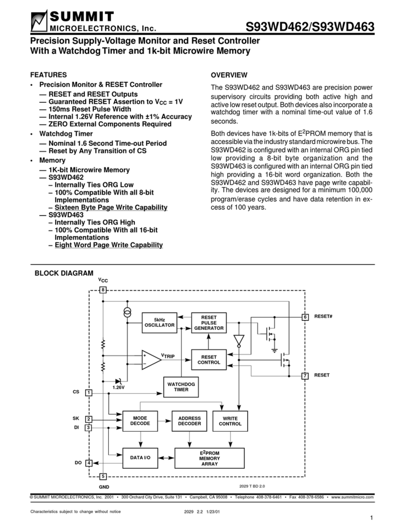
Summit S93WD462 User manual

Summit

Summit S93WD462 User manual

Summit HOTEL BOX HBOX168 User manual

Summit

Summit HOTEL BOX HBOX168 User manual

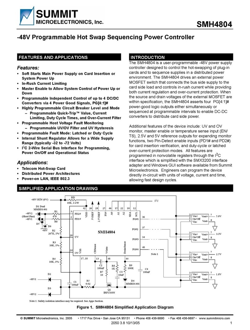
Summit SMH4804 User manual

Summit

Summit SMH4804 User manual

Popular Controllers manuals by other brands

Yardian PRO1900 user guide

Yardian

Yardian PRO1900 user guide

Behringer FC600 quick start guide

Behringer

Behringer FC600 quick start guide

Fortinet FortiADC 4000D quick start guide

Fortinet

Fortinet FortiADC 4000D quick start guide

USA Technologies VendingMiser VM180 EZ Installation Instructions

USA Technologies

USA Technologies VendingMiser VM180 EZ Installation Instructions

Mitsubishi q64rd user manual

Mitsubishi

Mitsubishi q64rd user manual

Rinnai MC-100V Operation and installation manual

Rinnai

Rinnai MC-100V Operation and installation manual

Hitachi PLC Getting started

Hitachi

Hitachi PLC Getting started

dSPACE DS1103 Hardware installation and configuration manual

dSPACE

dSPACE DS1103 Hardware installation and configuration manual

Siemens RWD45U Installation and commissioning guide

Siemens

Siemens RWD45U Installation and commissioning guide

Johnson Controls M9203-B Series installation guide

Johnson Controls

Johnson Controls M9203-B Series installation guide

Naturela NPBC-V3M manual

Naturela

Naturela NPBC-V3M manual

Kenwood KOS-V500 instruction manual

Kenwood

Kenwood KOS-V500 instruction manual

Iseo Atlas Plus DIN installation guide

Iseo

Iseo Atlas Plus DIN installation guide

SMC Networks ITV10*0-PR*-Q Series Installation and maintenance manual

SMC Networks

SMC Networks ITV10*0-PR*-Q Series Installation and maintenance manual

Hayward Aqua Solar GL-235 Operation and installation manual

Hayward

Hayward Aqua Solar GL-235 Operation and installation manual

Mitsubishi MELSEC A1SCPUC24-R2 Hardware user manual

Mitsubishi

Mitsubishi MELSEC A1SCPUC24-R2 Hardware user manual

Fusion Podium ESC 17T operating instructions

Fusion

Fusion Podium ESC 17T operating instructions

Akyga AK-CA-24 user manual

Akyga

Akyga AK-CA-24 user manual

manuals.online logo
manuals.online logoBrands
  • About & Mission
  • Contact us
  • Privacy Policy
  • Terms and Conditions

Copyright 2025 Manuals.Online. All Rights Reserved.