BROSA 0201 User manual

BROSA AG
Dr. Klein Straße 1
D-88069 Tettnang
Phone: +49(0)754 93 35 0
Fax: +49(0)754 93 35 35
www.brosa.net
BROSA Pte Ltd
5 Lorong Kilat #0 -01
Singapore 5981 6
Phone: +65 6795 3 4
Fax: +65 6795 4 8
BROSA B.V.
Galliershof 38
NL - 5349 BV Oss, Netherlands
Phone: +31 41 6146 0
Fax: +31 41 6146 86
BROSA (Nanjing) Co., Ltd.
Jinma Lu 3, Maqun Scientific Park, Qixia District
10049 Nanjing
Phone: +86 ( 5)8 4639
Fax: +86 ( 5)8 4639
................................
................................
................................
................................
................................
© 20
21
BROSA AG, Tettnang, Ger any
Operating Manual
BROSA Type 0 01 & 0 03 Force Measuring Pin
Version: 02/2021

BROSA Force Measuring Pin
© 0 1 BROSA AG, Tettnang, Germany English translation of the original
German document
/ 15
...............................................................................................................................................................
................................
................................
................................
................................
...............................
............................................................................................................................................................
................................
................................
................................
................................
............................
Notes

© 0 1 BROSA AG, Tettnang, Germany English translation of the original
German document
3 / 15
BROSA Force Measuring Pin
...............................................................................................................................................................
................................
................................
................................
................................
...............................
............................................................................................................................................................
................................
................................
................................
................................
............................
Contents
1 General information ................................................................................................ 4
1.1 Safety instructions – Explanation of symbols: .................................................... 4
Description of the BROSA force measuring pin ........................................................ 5
.1 Structure and functionality ................................................................................ 5
. Information on explosion protection .................................................................. 7
.3 Label (nameplate, indication of measuring direction) ......................................... 8
3 Advice on the safe handling of BROSA force measuring pins ................................... 9
3.1 Handling .......................................................................................................... 9
3. Installation and commissioning ....................................................................... 10
3. .1 General information ................................................................................. 10
3. . Additional information for operation in areas subject to explosion hazards . 11
3.3 Operation and maintenance ........................................................................... 1
3.3.1 Operation ................................................................................................ 1
3.3. Maintenance ........................................................................................... 13
3.4 Disassembly .................................................................................................. 13
3.5 Disposal ........................................................................................................ 14

BROSA Force Measuring Pin
© 0 1 BROSA AG, Tettnang, Germany English translation of the original
German document
4 / 15
...............................................................................................................................................................
................................
................................
................................
................................
...............................
............................................................................................................................................................
................................
................................
................................
................................
............................
1 General infor ation
Read the operating instructions and the product-specific documents carefully before
commissioning the sensor.
Make sure that the sensor is fully suitable for the applications in question.
Improper use or any use other than intended may result in a malfunction of the sensor or
undesirable effects in your application. For this reason, installation, electrical connection,
commissioning and maintenance of the sensor may only be carried out by trained personnel
authorized by the plant operator.
We also expressly point out that any liability is excluded if instructions in this documentation
are disregarded.
Current certificates can be downloaded from the BROSA AG website.
Only the German version of this operating manual represents the original document.
1.1 Safety instructions – Explanation of symbols:
WARNING! This symbol indicates dangers that can lead to personal injury and
property damage!

© 0 1 BROSA AG, Tettnang, Germany English translation of the original
German document
5 / 15
BROSA Force Measuring Pin
...............................................................................................................................................................
................................
................................
................................
................................
...............................
............................................................................................................................................................
................................
................................
................................
................................
............................
2 Description of the BROSA force easuring pin
.1 Structure and functionality
Type 0 01 and 0 03 BROSA force measuring pins are used to measure the force in double
shear connections in or on machines and devices of all kinds.
Fig. 1: Force measuring pin
The force measuring pin consists of a cylindrical measuring body (1), that absorbs the load to
be measured and exhibits the properties for torsional and axial securing (1a) as well as a
connection support ( ) firmly connected to the measuring body in some cases, on which - if
not placed directly on the measuring body - the necessary elements for the electrical
connection (plug or cable, 3) are attached and which - if not placed in the measuring body -
contains the measurement electronics. The recess (1b) in the measuring body for technical
measurement reasons can be provided with a filling depending on the application or
optionally on request. Optionally, the measuring body can contain elements to lubricate the
bearing (1c). The Ex d Type 0 03 force measuring pin is always equipped with a threaded
pin (4) for electrical potential equalisation (optional in the other types). The measuring body
and connection support, if applicable, are made of stainless steel.
The MOP force measuring pin contains integrated mechanical overload protection.

BROSA Force Measuring Pin
© 0 1 BROSA AG, Tettnang, Germany English translation of the original
German document
6 / 15
...............................................................................................................................................................
................................
................................
................................
................................
...............................
............................................................................................................................................................
................................
................................
................................
................................
............................
Figure : Installation conditions
The force measuring pin (1) is inserted into the mounting holes ( ) of the double-shear
connection, which have a corresponding diameter, and secured against unintended
movement by means of a pin holder (see Fig. 1, point 1a). Force F transmitted from the
connection is transmitted to the measuring electronics through analysis of the resulting
deformation of the measuring body and output as an electric signal.
Versions with two measuring directions (X-Y force measuring pin) and/or two measuring
systems, either with output signals on separate connectors/cables or combined in one
plug/cable, are available as options. More information can be found in the technical
datasheets, which can be obtained free of charge from BROSA.

© 0 1 BROSA AG, Tettnang, Germany English translation of the original
German document
7 / 15
BROSA Force Measuring Pin
...............................................................................................................................................................
................................
................................
................................
................................
...............................
............................................................................................................................................................
................................
................................
................................
................................
............................
. Information on explosion protection
The type 0 01 force measuring pin is optionally available in an intrinsically safe design for
use in potentially explosive atmospheres. This is done using a -wire amplifier
ExDANGmicro W_***. The following specifications apply:
Certificate number: BVS 16 ATEX E 041 IECEx BVS 16.0031
Ignition protection type: Ex II G Ex ib IIC T4 Gb Ex ib IIC T4 Gb
Voltage 30 V DC 30 V DC
Current 100 mA 100 mA
Power 750 mW 750 mW
Effective internal capacitance 4 nF + 0.3 nF/m 4 nF + 0.3 nF/m
Effective internal inductance 3 µH + 1 µH/m 3 µH + 1 µH/m
Ambient temperature -40 to +80°C -40 to +80°C
Use of intrinsically safe force measuring pins in zone 0 is not allowed.
The Ex d type 0 03 force measuring pin is designed to be pressure-resistant and is therefore
suitable for use in potentially explosive atmospheres.
Certificate number: BVS 09 ATEX E 037 X IECEx BVS 14.0110 X
Ignition protection type: II G Ex d IIC T4 Gb Ex d IIC T4 Gb
II G Ex d IIB T4 Gb Ex d IIB T4 Gb
Input voltage 9-36 V DC 9-36 V DC
Input current 5-100 mA 5-100 mA
Output current 0-10 V DC 0-10 V DC
Output voltage 4- 0 mA 4- 5 mA
Passive input voltage 1-10 V DC 1-10 V DC
Input current 3-30 mA 3-30 mA
Ambient temperature -40 to +80°C -40 to +80°C
WARNING! Use of the Ex d force measuring pin in zone 0 is not allowed.
Current certificates can be downloaded from the BROSA AG website.

BROSA Force Measuring Pin
© 0 1 BROSA AG, Tettnang, Germany English translation of the original
German document
8 / 15
...............................................................................................................................................................
................................
................................
................................
................................
...............................
............................................................................................................................................................
................................
................................
................................
................................
............................
.3 Label (nameplate, indication of measuring direction)
Each BROSA force measuring pin is equipped with a nameplate containing the respective
information applicable for the given product. Depending on the structural design, it can be
attached either on the front (Figure 3, 1a) or on the long sides (Figure 3, 1b).
Figure 3: Nameplate positions, measuring direction
Figure 4: X-Y FMP measuring direction
The measuring direction is indicated on the front side with an arrow (Figure 3, ). A simplified
indication of the measuring direction (omission of the two lower arrows shown in Figure 3) is
possible.
In the optionally available version with two measuring directions, the measuring directions
are labelled as shown in Figure 4.

© 0 1 BROSA AG, Tettnang, Germany English translation of the original
German document
9 / 15
BROSA Force Measuring Pin
...............................................................................................................................................................
................................
................................
................................
................................
...............................
............................................................................................................................................................
................................
................................
................................
................................
............................
3 Advice on the safe handling of BROSA force easuring
pins
WARNING! Non-compliance with the following instructions can lead to sensor damage
and/or impairment of measurement results. The analysis of an erroneous measurement can
result in personal injury or material damage.
WARNING! Despite their sturdy design, BROSA force measuring pins may not be used
for any other than the intended purpose (see. Section 1.1). With improper use, dangers to life
and limb of the user or third parties and/or impairment of the device in which the force
measuring pin is implemented or other material assets can be caused.
3.1 Handling
WARNING! BROSA sensors contain high-quality measurement electronics. Make sure
they are handled carefully.
- BROSA force measuring pins are delivered in transport-safe packaging. We
recommended that you remove the sensors from the package immediately prior to
installation.
- The mass of the force measuring pin is to be observed when selecting appropriate
handling equipment and/or lifting gear; it is indicated on the nameplate.
- BROSA force measuring pins must be secured against falling. Do not throw sensors!
- Use as a tool (e.g., impact, slotting or lever tool) is not permitted; it can cause
damage to the sensor and thus falsify the measurement results.

BROSA Force Measuring Pin
© 0 1 BROSA AG, Tettnang, Germany English translation of the original
German document
10 / 15
...............................................................................................................................................................
................................
................................
................................
................................
...............................
............................................................................................................................................................
................................
................................
................................
................................
............................
3. Installation and commissioning
3. .1 General information
We recommended taking the following actions in the given order using the “four-eye
principle”.
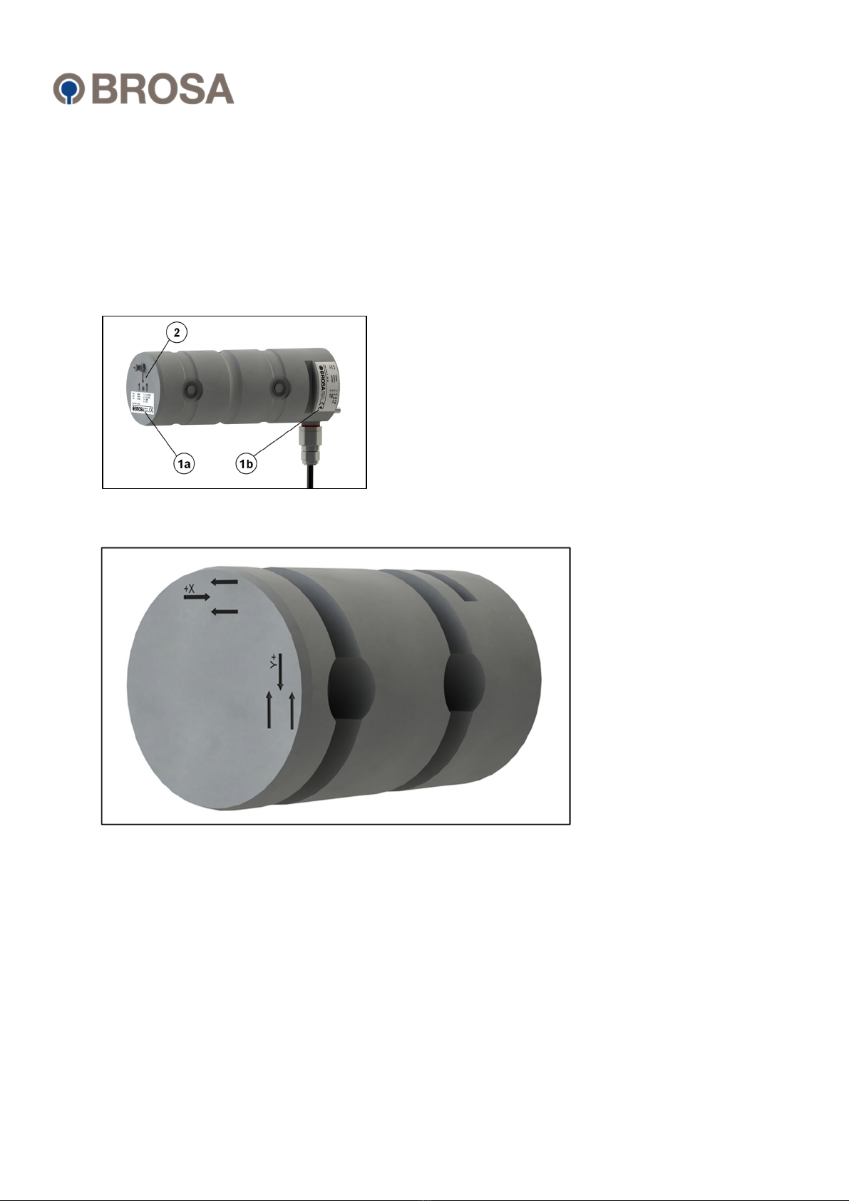
a) Checking the sensor-measuring point assignment: It must be ensured that the sensor
to be installed is designed for use at the intended measuring point. For this purpose,
check information on the nameplate, in particular the item or the identification number
and the measuring range, against the data of the measuring point.
WARNING! A sensor not designed for the particular measuring point must not be
installed.
b) Inspection of the sensor for intactness and function: It must be ensured that the
sensor to be incorporated is free of damage of any kind.
WARNING! A damaged sensor must not be installed!
c) Installation of the sensor in the measuring point: The force measuring pin is to be
aligned on the intended contact surface according to the offer drawing.
WARNING! The force measuring pin must not be driven in using impact tools!
After alignment, the force measuring pin must be secured against movement and rotation
using the elements provided for this purpose. Attention must be paid to the correct alignment
of the force measuring pin to the intended measuring direction (see front mark, compare
Section 1. .)
WARNING! A misaligned sensor leads to erroneous measurement results!
d) Establishment of electrical connection: The elements on the sensor for the electrical
connection are to be connected to the power supply, the earth connection if
necessary, and the evaluation system of the device. In doing so, the information
given on the nameplate for plug or cable assignment and, if applicable the installation
guidelines of the cable, are to be observed.

© 0 1 BROSA AG, Tettnang, Germany English translation of the original
German document
11 / 15
BROSA Force Measuring Pin
...............................................................................................................................................................
................................
................................
................................
................................
...............................
............................................................................................................................................................
................................
................................
................................
................................
............................
WARNING! An incorrect or incomplete electrical connection impairs or prevents
measurement.
e) Functional check: After completed mechanical (see c) and electric (see d) installation,
load on the sensor is to be applied over the entire measuring range; the output
measurement signals are to be subjected to a plausibility check.
WARNING! If due to unusual events (e.g., deformation or unusual noise),
measurement results are considered implausible or there is suspicion that the sensor is
malfunctioning for any other reason, it must not be put into operation.
3. . Additional information for operation in areas subject to explosion hazards
Only those sensors with the corresponding labels are approved for use in areas subject
to explosion hazards.
If the open cable end is connected inside an area subject to explosion hazards, the connection
must be inside a terminal box/switching cabinet certified in accordance with the ATEX-
directive. If it is connected outside an area subject to explosion hazards, it must be in line with
the general requirements for electrical equipment.

BROSA Force Measuring Pin
© 0 1 BROSA AG, Tettnang, Germany English translation of the original
German document
1 / 15
...............................................................................................................................................................
................................
................................
................................
................................
...............................
............................................................................................................................................................
................................
................................
................................
................................
............................
3.3 Operation and maintenance
3.3.1 Operation
BROSA force measuring pins operate automatically; attaching tools is not required for
operation. Direct manual intervention by the operator is not necessary; there are therefore no
requirements for the operator to wear protective equipment during operation. However, the
relevant requirements for the device in which the force measuring pin is implemented must
be observed.
BROSA force measuring pins emit neither airborne acoustic noise nor non-ionizing radiation.
Operation of BROSA force measuring pins is permitted only within the parameters and
properties given in the technical datasheets and on the nameplate. These are, among others:
- Measuring range
- Temperature range
- Permissible supply voltage
- Electrical protection class
- Material
It must be ensured that no parasitic influences such as forces transverse to the measuring
direction are transmitted via the force measuring pin.
Inductive or capacitive coupling with the connection cable(s) of the sensor can distort the
measurement result and must be avoided. Some examples of these kinds of couplings can
be caused e.g., by unfavourable cable routing (parallel power lines, frequency converters,
transformers, motors, incorrect grounding/shielding and the like).
When performing electric welding in the vicinity of the sensor, all connections must be
disconnected and isolated. It must be ensured that no welding current is flowing through the
sensor.
WARNING! Operation outside the specified parameters or contrary to existing
properties or improper use can damage the sensor and cause it to fail or lead to faulty
measuring results. If the sensor is overloaded, this can lead to the whole machine being
equally overloaded and possibly endangering its stability.

© 0 1 BROSA AG, Tettnang, Germany English translation of the original
German document
13 / 15
BROSA Force Measuring Pin
...............................................................................................................................................................
................................
................................
................................
................................
...............................
............................................................................................................................................................
................................
................................
................................
................................
............................
3.3. Maintenance
In its capacity as a sensor, BROSA force measuring pins are maintenance-free. As load-
transmitting elements, however, they are subject to mechanical stress, requiring regular
inspections of the fault-free state of each force measuring pin. The intervals between
inspections depend on the intensity of use and must be determined by the end-user. Additional
lubrication holes are not necessary for the sensor to function, but are used to lubricate
secondary components, so the end-user is responsible for the lubrication cycles.
An inspection includes the following points:
- Visual inspection for damage to the measuring body and wiring as well as
contamination.
- Function test/plausibility check
The causes of existing errors are to be identified and remedied. If the test indicates an improper
sensor state, it must be taken out of operation. If a malfunction or damage is detected on the
sensor, it must be sent to the manufacturer's factory for diagnosis and, if necessary, repaired.
WARNING! The sensor may only be repaired at the factory. Intervention (e.g., opening,
mechanical processing and the like) done by parties other than the manufacturer means the
safe operation of the sensor is no longer ensured and voids the guarantee and warranty.
3.4 Disassembly
We recommend performing the following actions in the order given.
a) Establishment of a load-free state at the measuring point: The force measuring pin is
to be unloaded before removal.
WARNING! Removal of a force measuring pin under load poses serious dangers to the
life and limb of bystanders and can cause major damage. This is therefore not permitted.
b) Undoing the electrical connection
c) Remove the mechanical securing elements
d) Remove the force measuring pin
WARNING! If the force measuring pin is to be reused, it must not be removed using
impact tools!

BROSA Force Measuring Pin
© 0 1 BROSA AG, Tettnang, Germany English translation of the original
German document
14 / 15
...............................................................................................................................................................
................................
................................
................................
................................
...............................
............................................................................................................................................................
................................
................................
................................
................................
............................
3.5 Disposal
If the end of the service life is reached, the force measuring pin is to be disposed of in an
environmentally friendly way. Since the non-metallic components are a small proportion
compared to the mass of the force measuring pin, it can be recycled as a whole as scrap
steel. BROSA sensors are usually made of stainless steel and can be disposed of
accordingly.
If the sensor is stored before final disposal, an appropriate storage location is to be selected
which prevents harmful substances from entering the environment. If necessary, the sensor
must be cleaned.
WARNING! BROSA force measuring pins contain traces of environmentally hazardous
substances. This is also true of the impurities created during use. Contamination of the
environment by these substances is to be prevented.

© 0 1 BROSA AG, Tettnang, Germany English translation of the original
German document
15 / 15
BROSA Force Measuring Pin
...............................................................................................................................................................
................................
................................
................................
................................
...............................
............................................................................................................................................................
................................
................................
................................
................................
............................
This manual suits for next models
1
Table of contents
Other BROSA Measuring Instrument manuals