Brother BAS-411 User manual

SERVICE
MANUAL
FOR
BAS
-4
11
BAS-415
SINGLE HEAD ELECTRONIC EMBROIDERY
MACHINE
I
· ·
.
~
-
From the library of: Superior Sewing Machine & Supply LLC

CONTENTS
(
PART
NAMES )
·.
· · · · · · · · · · · · · · · · · · ·· · · · · · · · · · ·· · · · · · · ·· · ·· · · · · · · · ·· · · · ·· · · · · · · · · · · · · · · · 1
( MECHANICALDESCRIPTIONS ) · · · · · · ·· · · · · · · ·· · · · · · · ·· · · · · · ·· · · ·· · · · · · · · · · · ·· · · · · · · · 3
[I] .upper
shaft
mechanism . .. . . •. . . . . .. . . . . . . . . . . ••. . . . . .. . •. . . . . . . . . .•. . •• . . •. .. . . . . . . . . . 3
00
Lower
shaft
and
rotary
hook
mechanism . . . . . . •••••. . . . . .. . . . . . . . . •. .. ••. . ••. . . . . . . •. . . . 4
00
Thread
trimmer
mechanism . •. . . . . . . . . . •. . . . . .. . . . . . . .. . . . . . . . . . . .. . . . . .•. . . . . . ••••••. • 5
[j]
Thread
wiper
mechanism . •. . •. . . . . . . . . . . . . .•. •. . . . . . . . . . . . . . . . . . .•••••. ••. •.. . . . . . •. . . 6
[§] Needle
bar
flip-up
mechanism . . ••. . . . . . . . . . .. . . . . . . . . . . .. . . . . . . . . .. . . •.. . . . . . . . . •••. ••. 7
[§] Pickermechanism •. . . . . . . . . . . . . . . . . . . . . . . . . . .•. ••. . . . . . .•. . . . . . . •. •. . ••. •. . . . . . •. . . . . . 8
[1]
Drive, (X)
feed
mechanism . . . . . . . . . . . . . . . . . . . .. . . . . . . . . .. . •••. . . . •. . . •. . . . . . . . . . . . . . . •. 9
[I]
Drive, (Y)
feed
mechanism . . . . . . . . . . . . . . . . . . . .•. •. . . . . . . . . . .. . . . . •. •. . •. . . .. . . . . . . . ••. 10
( STANDARDADJUSTMENT ) · · · · · ·· · · · · · · · · · · ·· · ·
·.
· · · · ·· · · · · · ·· · · · · ·· · · · · · · ·· · · · · · · · ·
11
[I]
Adjusting
needle
bar
height
...•..............••......
~
. . . . .. . . . ••. . . . . . . . •. .•••••••••
11
~
Adjusting
timing
of
needleand
rotary
hook
. . •. . . ••. . . . . .. . . . . . . . . . .. . . . . . . . . . . •. ••••. • 13
00
Adjusting
cloth
presser
height
. . . . . .. . . . . . . . . . . . . . . . .. . . . . . . . . . . . .•. •. . . . . . . . .. . . . . . . •. 13
[j]
Adjusting
knife
and
fixed
knife
. •. . . . . . . . . . . . . ••. . . . . . .. . . . . . . . .. •.. . . . . . . . . . . . . . . . . . . . 14
[§]
Adjusting
picker . . . . . . . . . . . . . . . . . . . . . . . •. .. . . . . . . . . .. . . . . . . •. . . . .. . . . . . . . . . . . . . ••• •. . 15
[§]
Adjusting
the
thread
wiper
. . . . . . . . . . . . . . . . . . . .. . . . . . . . .. •. . . . . . . .•. . . . . . . . .•. . . . . . . •• 16
[1]
Adjusting
wire
tension
.....•.................•........................••...•.•...••••
17
1.
X-
feed
wire
. . . . . . . . . . . . . . . . . . . . . . . . . . . .. •. . . . . . .. . . •.. . . . . •.. . . . . . . . . . . . •. •••••. 17
2.
Y
-feed
wire
. . . . . . . . . . . . . . •. . . . . . . . •. . . . . . . . . . . . . . .. . . . . . . . . . . . . •. . . . . .. . . . . •. . . . 18
00
Adjusting
thread
breakage
detect
stud
..........................•.•.....•.•............
19
00
Adjusting
bobbin
winder
...................•.........................................
20
lim
BAS-411·415
test
mode
. . . . . . . . . . . . .. . . . . . . . . . . . . . . . . . .. . . . . . . . . . .••••••. . . . •. . . . . . . . .
21
In]
Adjusting
synchronizer . . . . . . . •. •. . . . . .. . . . . . . . . . . . . .. . . . . . . . . . . . .. . . . . . . . . . . . . . •. . . . . 23
1m
Adjusting
home
position
using
home
position
plate
. . . . . .. . . . . . . . . . •. . . •. . . . . . . . . •. . . . . . 26
lj}
Positioning
over
limit
sensor
...................................•..••..•...............
28
IB1
How
to
adjust
thread
sensor(thread breakage detector) . . . . . . . . . . . . . .. . . . . . . . . . . . •. . . . . . 35
( LUBRICATION ) ·· · · · · · · · · · · · · · · · · · · · · · · · · · · · ·· · · · · · · · · · · · · · · ·· · · ·· · · · · · · · · ·· · · · · · · · · · · 36
[I]
Machine
head . . . . . . . . . . . . . . . . . . . . . . . . •. . . •. . . . . . . . .. . . . . . . . . . . . .•••••. . •. . . . . . . . . . . . 36
~
Feed
guide
mechanism
.......................................•........•..............
38
From the library of: Superior Sewing Machine & Supply LLC

(
REPLACINGANDADJUSTINGPARTS)
· · · ·
··
· · · · · · · · ·· · · ·
··
· · · ·
··
· · · · · · · ·
··
· · · · · · ·
··
39
[I]
Removing and
adjusting
machine head (1) . . . .. . . . . . . . . . .. . . . . . . . . . . . . . . . . . . . . . . . . . . . . . 39
~
Removing and
adjusting
machine head (2) .
..
. . . . .
..
.
..
..
. . . . . . .
..
.. . . .
....
..
......
. . . . 40
lm
Removing needle
bar
case
............................................................
41
1!1
Replacing
up
and
down
motion
parts . . . . . . . . . . . .. . . . . . . . . . . . . . .. . . . . . . . . . . . . . . . . . . . . . . 42
~
Replacing
jump
solenoid
..............................................................
43
[§]
Attaching
X
wire
.....................................................................
44
[1]
Attaching
Y
wire
.....................................................................
45
(
ELECTRIC
COMPONENTS ) · · · · · ·· · · · · · · · · ·· · · · · · · · · ·· · · · · · · · · · · · ·· · · · · · · ·· · · · · · · · · · 46
[!)
Circuit
board
locations
...•............................................................
46
~
Replacing
circuit
board
...............................................................
47
00
Fuses
...............................................................................
58
(!]
P-ROMS
. . . . . . . . . . . . . . . . . . . . . . . . . . . . . . . . . . . . . . . . . . . . . . . . . . . . . . . . . . . . . . . . . . . . . . . . . . . . . 60
~
DIP switches . . . . . . . . . . . . . . . . . . . . . . . . . . . . . . . . . . . . .. . . . . . . . . . . . . . . . . . . . . . . . . . . . . . . . . . . . 62
[§]
Connectors . . . . . . . . . . . . . . . . . . . . . . . . . . . . . . .. . . . . . . . . . . . .. . . . . . . . . . . . . . . . . . . . . . . . . . . . . . 67
[1]
troubleshooting
flowchart
...........................................................
70
BAS-411
..........................................................................
70
BAS-415
..........................................................................
81
00
Harness connectionsand connectors
number
...........................................
92
(
EXPLANATIONOFOPTIONALPARTSINSTALLATION)
·· · · · · · · · ·· · · · · · · · · · · · · · · · · 106
[]]
ML
6511ampset . . . . . . . . . . . . . . . . . . . . . . . . . . . .. . . . . . . . . . . . . . . . . . . . . .. . . . . . . . . . . . . . . . . 106
~
Light
marker
. . . . . . . . . . . . . . . . . . . . . . . . . . . . . . .. . . . . . . . . . .. . . . . . . . . . . . . . . . . . . . . . . . . . . . 107
00
Connecting
optional
parts
with
machine . . . . . .
..
..
. . . . . . .. . . . . .
....
. . . .
..
. .
..
. . . . .
..
. 112
1!1
Bobbin
winder
. . . . . . . . . . . . . . . . . . . . . . . . . . . . . . .. . . . . . . . . .. . . . . . . . . . . . . . . . . . . . . . . . . . . . 116
(
TROUBLESHOOTING)·····························································
118
[!) Mechanical
problem
. . . . . . . . . . . . . . . . . . . . . . .. . . . . . . . . . . .. . . . . . . . . . . . . . . . . . . . . . . . . . . . 118
~ Electrical
problem
. . . . . . . . . . . . . . . . . . . . . . . . .. . . . . . . . . . . . .. . . . . . . . . . . . . . . . . . . . . . . . . . . . 120
00
List
of
error
messages . . . . . . . . . . . . . .. . . . . . . . . . . . . . . . . . . . .. . . . . . . . . . . . . . . . . . . . . . . . . . . . 122
BAS-411 . . . . . . . . . . . . . . . . . . . . . . . . . . . . . .. . . . . . . . . . . . . . . . . . . . . . . . . . .. . . . . . . . . . . . . . . 122
BAS-415 . . . . . . . . . . . . . . . . . . . . . . . . . . . . . . . .. . . . . . . . . . . .. . . . . . . . . . . . . . . . . . . . . . . . . . . . 125
BAS-411 KEYBOARD
UN
IT CONTROL
BLOCK
DIAGRAM
BAS-415 KEYBOARD UNITCONTROL
BLOCK
DIAGRAM
BAS-411 CONTROL
BLOCK
DIAGRAM
BAS-41
5 CONTROL
BLOCK
DIAGRAM
.........................................................
.........................................................
From the library of: Superior Sewing Machine & Supply LLC

(
Part
names
)
(
BAS-411
)
0 Thread
guide
bar
@ Thread tension dial
@)
Thread take-up
0 Embroidery
hoop
<9
Table plate 6 Operation panel
@)Spool
shaft
(B)
(!) Keyboard assembly
CD
Guard bar
@ Speed dial
4D
Disk drive
-1-
0 Thread take-upcover
@)
Powerswitch
48
Contrastdial
of
liquid
crystal display
From the library of: Superior Sewing Machine & Supply LLC

( ·
BAS-415
)
0 Thread
guide
bar 8 Thread tension dial
@)
Thread take-up
@ Embroidery
hoop
(!) Table
plate
8 Operation panel
@)
Spool
shaft
(B)
tD)
Keyboard assembly
4D
Guard bar
Q) Speed dial
4D
Disk drive
-2-
8 Thread take-upcover
~
Powerswitch
C8
Contrastdial
of
liquid
crystal display
From the library of: Superior Sewing Machine & Supply LLC

(MECHANICAL
DESCRIPTIONS )
lii Upper shaft
mechanism
1)
When
the
pulley 0 rotates
in
the
direction
of
the
arrow,
it
transmits
the
rotation
to
the
uppershaft
8.
The upper.shaft8 then rotates
the
threadtake-updriving
cam
@).
2)
The threadtake-updriving
cam@)
transmits
the
motion
to
the
connecting rod
9.
3)
The
up
and
down
motion
parts
<9,
attached
to
the
main needle bar
0,
move
the
needle bar 8 upand
down.
4)
The needle bar8
is
guided by
the
needle bar
case
@).
-3-
From the library of: Superior Sewing Machine & Supply LLC

~
Lower shaft and rotary hook mechanism
1)
When
the
pulley 0 rotates
in
the
direction
of
the
arrow,
it
transmits
the
rotation
to
the
uppershaft @.
The upper
shaft@
then rotates uppershaftgear(A)@).
2)
Uppershaftgear
(A)@)
transmits
the
movement
to
the
lower
shaftgear0 via the vertical shaft
e.
3)
The
lower
shaftgear 0 transmits
the
rotation
to
the
attached lowershaft
@).
Then
the
rotary hook
6,
attached
to
the
lower
shaft@), rotates in
the
direction
of
thearrow.
NOTE:
In BAS-
411
and 415,
the
rotary hookmakes
two
revolutions
for
each revolution made by
the
pulley.
-4-
From the library of: Superior Sewing Machine & Supply LLC

~
Thread trimmer
mechanism
-------------------
After
the
final stitch, roller shaft (A) 0
moves
into
the
groove
of
the
cam
@,and connecting plate
(B)
@)
~
moves.
Then the knife 0 engages
with
thefixed knife
0,
trimmingthe thread.
-5-
From the library of: Superior Sewing Machine & Supply LLC

II]
Thread
wiper
mechanism
~--------
After
sewing
is
completed,
the
thread guide solenoid 0
moves
the
plate
@in
the direction
of
the
arrow,
and
the
upper thread guide hook
@)
attached
to
the plate @ brings the trimmed thread
to
the
thread
presser.
The thread presser
secures
thetrimmedthread.
-6-
From the library of: Superior Sewing Machine & Supply LLC

[§]
Needle
bar
flip-up
mechanism
~~------
After
receiving
the
set needle bar
flip-up
signal,
cam
gears (A) 8 and
(B)
@)
attached
to
the
pulse
motor
0
are
activated.
The needlebar
flip-up
is
performed
by
the
changecam
9.
-7-
From the library of: Superior Sewing Machine & Supply LLC

[§]
Picker
mechanism
------------
The
picker solenoid 0 functions
at
the
beginning
of
sewing and after thread trimming.
The
picker
@)
attached
to
connecting plate
(A)@
moves inthe direction
of
the bobbin
case
e,then pullsthe upperthread
under
the
material.
Duringthread trimming,
the
picker@) operates
to
keep the needle thread length constant.
-8-
From the library of: Superior Sewing Machine & Supply LLC

[1]
Drive, (X) feed mechanism
1)
Pinion gear
(B)
@ attached
to
the X-pulse motor 0 rotates, then transmits the rotation
to
idle gear (A)
@).
2)
When idlegear(A)@) rotates, the (X) wire
CD
reeled inthewire drum
(X)
e moves
the
carriage & in
the
direction
of
the
X-axis
(left
e right) via
the
pulley
<9.
-9-
From the library of: Superior Sewing Machine & Supply LLC

[II.
Drive, (Y) feed
mechanism
1)
Pinion gear(B)@
of
theY-pulse motor0 rotates, thentransmitsthe rotation
to
idlegear
(A)@).
2) When idlegear (A) @)rotates, the
(Y)
wires @)(left) and (right) reeled in
the
wire drums
(Y)
8 on
the
right
and the
left
move the carriage
fi
in the direction
of
theY-axis (backwards e forwards) via the
pulley8.
-10-
From the library of: Superior Sewing Machine & Supply LLC
c
STANDARD
ADJUSTMENT
)
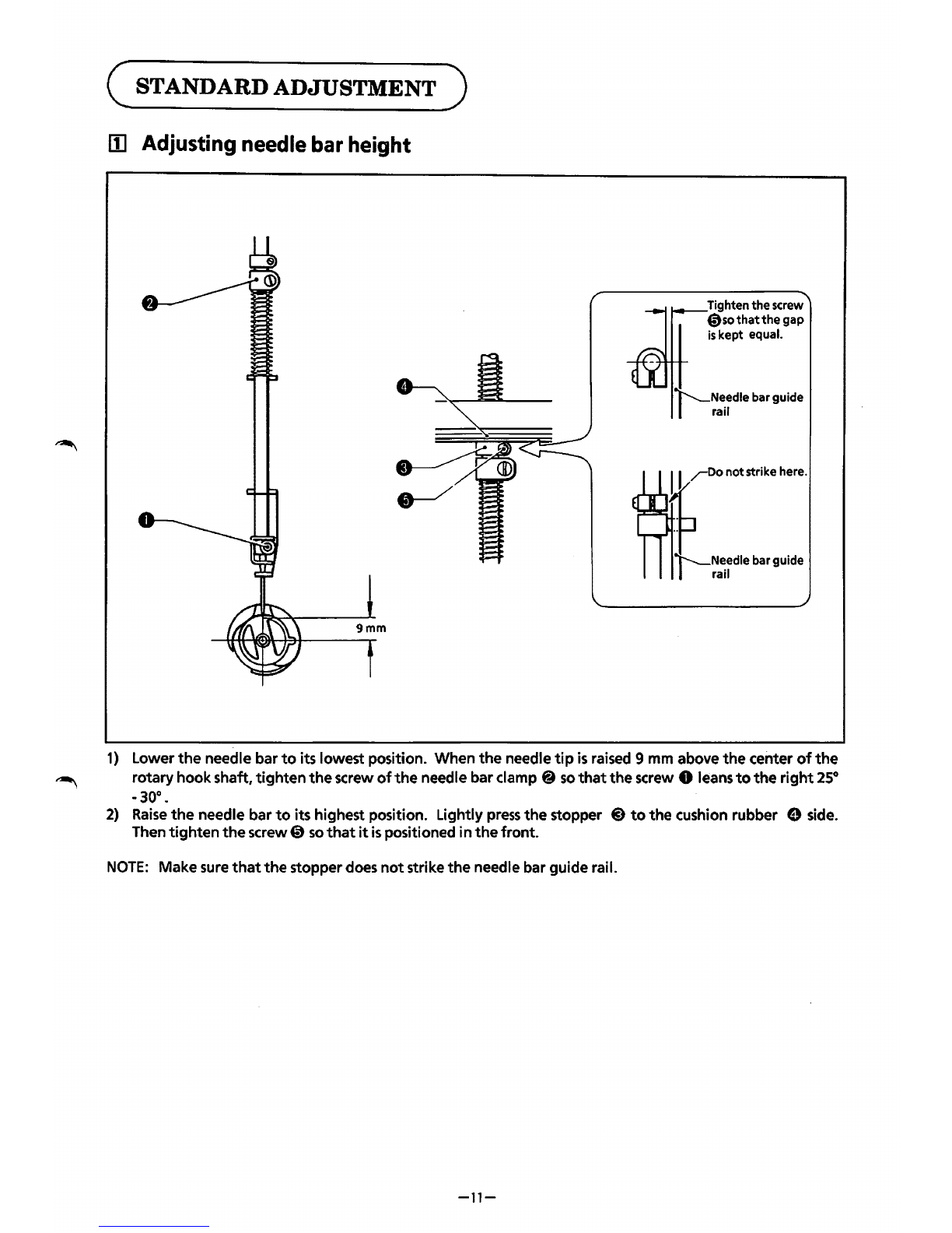
lii
Adjusting
needle
bar
height
Tightenthescrew
0so
that
the
gap
is
kept equal.
1)
Lower
the
needle bar
to
its lowest position. When
the
needle
tip
is
raised 9 mm above
the
center
of
the
~
rotaryhookshaft,
tighten
the
screw
of
the
needle barclamp @
so
that
the
screw 0 leans
to
the
right
25°
-30°.
2)
Raise
the
needle bar
to
its highest position. Lightly
press
the
stopper
@)
to
the
cushion rubber 9 side.
Then
tighten
the
screw0
so
that
it
is
positioned in
the
front.
NOTE:
Make sure
that
the
stopperdoes
not
strike
the
needle bar guide rail.
-11-
From the library of: Superior Sewing Machine & Supply LLC

When using
the
gauge (optional)
Gauge
1)
Loosen
thescrew 0 and remove
the
rotary
hook@
from the lowershaft.
2)
Insertthe gauge (option)
into
the lowershaft.
3)
Loosen
the
screw e
of
the
needle bar clamp
@).
Turn
the
pulley until the needle
tip
lightlycontacts
the
gauge
at
its lowestposition.
NOTE:
Do
not
use
the
flat
part
of
the
gauge
at
thistime.
4)
Tighten
the
screw 9
of
the
needle bar
clamp@)
firmly.
-12-
From the library of: Superior Sewing Machine & Supply LLC

~ Adjusting timing
of
needle and rotary hook
1/
I I
I
I I
I I
I I
: I
1)
Selectthefirstneedlebar
0.
\
I
I
I
I
I I
I I
I I
2)
Remove
the
two
screws and
the
needle plate@.
Aprrox.1 mm
2.5mm
3)
When
the
needle bar
is
raised
2.5
mm
(201°)
above its lowest position (180°), loosen
the
screw 0
of
the
rotary hook
@),
and adjust
so
that
the
needle meets
the
rotary hook point. Then, temporarily
tighten
the
two
stopscrews.
At
thistime,
the
needle barheightshould be about 1mm. {Figure A) .
4)
As
for
other needle bars,
if
the
gap between
the
needle and rotary hook
point
is
0.01
-
0.2
mm,
tighten
the
3screws
of
the
rotary hook.
~
Adjusting cloth presser height
Cutand insert.
Adjust
the
cloth presser 0
height
with
the
cushion rubber
@).
The cloth presser 0 heightshould be raised 1
-
1.5
mm
from
the
needle plate @
at
the
cloth presser's lowest position. {Asheet
of
the
cushion rubber
is
0.5
mmthick.)
~13-
From the library of: Superior Sewing Machine & Supply LLC

(j] Adjusting knife
and
fixed knife
1.
Attaching fixed knife
1)
Attach
the
fixed knife
so
that
the
attached part parallels
the
rotary hook
base.
The movable knife
broadens
at
part®.
Makesure
the
fixed knife doesn'tcontact
it
at
thispart.
2.
Knife timing
1)
While pushing
the
cam
lever 0 up
with
a finger, rotate
the
pulley @ in
the
direction
of
the
arrow.
When
the
knife
@)
begins
to
move,
the
pulley
will
become harder
to
turn.
At
thistime,tighten
the
screw
of
the
24 Jgear eI
fix
the
cam
CD
by hand
so
it
does
not
rotate, and
turn
the
pulley.
The
rotary hook
bladeshould be in
the
center
of
the rotaryhooksupporter@).
2)
Tighten
the
screw
of
the
24 J gear e
so
there
is
no backlash
of
the
cam
in
the
direction
of
the
lower
shaft. While pushing
the
cam
lever 0 up
with
a finger, rotate
the
pulley @again. When
the
knife
@)
begins
to
move,
the
blade in
the
rotary hookshould be in
the
center
of
the
rotaryhooksupporter
@).
3.
Knife position
Loosen
the
screw & and adjust
the
knife
@)
position
so
that
its end projects 1 mm beyond
the
fixed
knife'stip.
After
threadtrimming,
the
knifeshould be in this position.
If
the
knife does
not
stop
at
the
stop position,
the
uppershaft
will
be locked and
it
cannot make one
full
revolution. In
that
case,
move
the
knife
to
the
stop position byhand.
4.
Knife and fixed knife
1)
With
a marker, color
the
back
of
the
knife
@)
and engage
it
with
thefixed knife
@)
manually.
Check
that
the
colored portion
is
shaved equally.
This
shows properknifeengagement.
2)
If
the
engagement
is
wrong, loosen
the
screw
@)
of
the
fixed knife
@)
and adjust
the
inclination
with
the
lower
set screw
CD).
NOTE:
The inclination
of
the
fixed knife @)should
be
adjusted
with
the
two
top
screws
@)
and
the
bottomsetscrew
CD).
NOTE:
This
is
fineadjustment. Adjust carefully.
-14-
~-
From the library of: Superior Sewing Machine & Supply LLC

1§1
Adjusting
picker
FigureA
1)
Insert
the
bobbin
case
0 containing
the
bobbin
into
the
rotaryhookand set
the
picker@ position.
2)
Leave
the
solenoid arm
@)
pushed
to
the
needle bar side, then
tighten
connecting plate (A) e
with
the
screw0.
3)
Adjust
the
picker @
so
that
there
is
no
looseness and
so
that
it
functions lightly. Then
tighten
the
picker
bracket(!)
with
the
screw
8.
4)
Adjust
the
gap between
the
point
of
the
pickerand
the
bobbin
to
1
-1.5
mm.
Leave
the
solenoid arm
@)
pushed
to
the
pulleyside (thesolenoid operation position), thentighten
the
screw@).
5)
Adjust
the
picker position
so
that
it
is
bisected by
the
bobbin
case
spring
(see
figureA).
-15-
From the library of: Superior Sewing Machine & Supply LLC

[§]
Adjusting
the
thread wiper
1)
With
a finger, move
the
solenoid arm 0 in
the
direction
of
the
arrow.
Loosen
the
two
screws @ then
adjust
the
upperthread guide
hook@
so
that
it
movesslightly.
2)
Adjust
the
upperthread guide hook @
so
that
itscut part
is
located
at
the
center
of
the
needle hole.
-16-
From the library of: Superior Sewing Machine & Supply LLC

111
Adjusting
wire
tension
1.
X-feed wire
0 1.5 kg
Using a 1.5 kg
torque
wrench
or
a similar
tool,
push
at
the
location marked by
the
arrow
and adjust
so
there
is
a deflection
of
approximately
14
mm.
How
to
adjust
1)
Remove
the
seven screws 0 and
the
two
covers
(LR,
LL)@.
2)
Loosen
the
two
screws 0
of
both
hook
(LX)
@)
and hook
(RX)
0.
3)
There are
two
stoppers (U)
(S)
on
the
right
and
the
left
sides.
Turning them clockwise
will
increase
the
tension and
turning
them counterclockwise
will
decrease
the
tension.
4) When
the
tension
is
proper,
tighten
screw
0.
5)
After
tightening
screw
0,
firmly
retighten stoppers
(U)
(S)
so
there
is
no
looseness.
-17-
From the library of: Superior Sewing Machine & Supply LLC
Other manuals for BAS-411
3
This manual suits for next models
1
Table of contents
Other Brother PDA manuals


