Broughton 1450/850 LADDERSPAN User manual

BROUGHTON PLANT HIRE & SALES
1450/850 LADDERSPAN / 1450/850 MULTI RUNG
USERS GUIDE

ERECTION
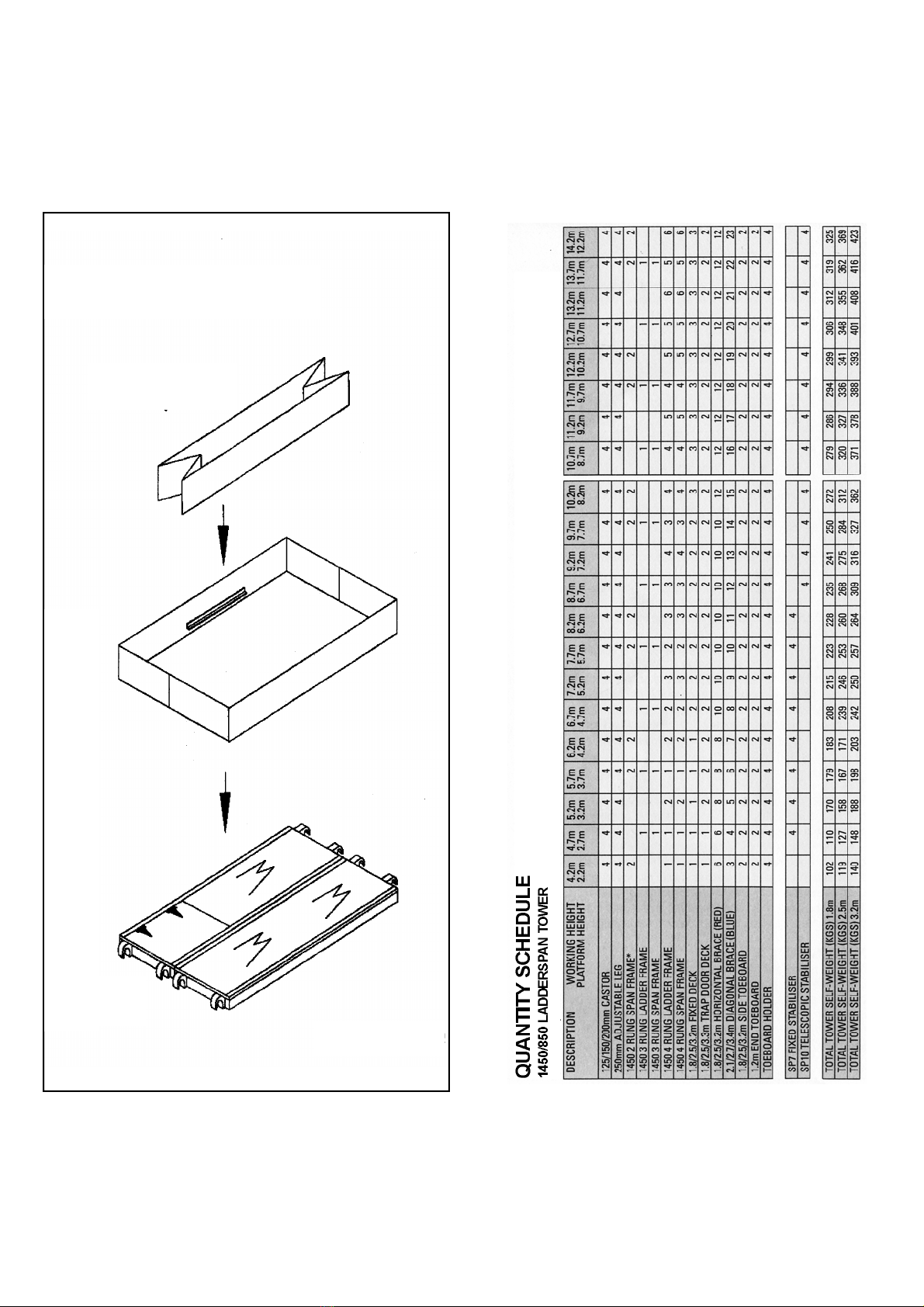
Check that all components are on site and they are
functioning correctly - See Quantity Schedule
Check if the ground on which the mobile access tower is to be
erected and moved, is capable of supporting the tower.
During the erection of the tower it is recommended that a
temporary guardrail brace be employed.
The safe working load is 275 kgs (606 lbs) uniformly distributed -
maximum concentrated load 150 kgs (330 lbs) per deck up to a
maximum of 950 kgs (2100 lbs) per tower (including self weight).
This must not be exceeded
Towers must always be climbed from the inside during assembly
and using the built-in ladder provided during use.
Do not use boxes or step ladders on the platform to gain
additional height.
LIFTING OF EQUIPMENT
Tower components should be
firmly secured by a reliable lifting
material (eg rope), employing a
reliable knot (eg clove hitch), to
ensure safe fatening
STABILISERS/BALLAST
Stabilisers or outriggers and ballast weights shall always be
fitted when specified.
Ballast is used at the base to stabilise towers against
overturning. The QUANTITY SCHEDULE shows the recommended
stabilisation. In circumstances where there is restricted ground
clearance for stabilisers/outriggers, contact your supplier for
advice.
It must be of solid materials (i.e. not water or loose sand) and
should not be positioned to overload individual legs. Ballast
should be secured agains accidental removal, and be
supported on the lowest rung of the bottom frame.
MOVEMENT
The tower should only be moved by manual effort, and only
from the base.
When moving the tower, beware of live electical apparatus,
particularly overhead, plus wires or moving parts of machinery.
No personnel or materials should be on the tower during
movement.
Caution should be exercised when wheeling a tower over
rough, uneven or sloping ground, taking cars to unlock and lock
castors. If stabilisers are fitted, they should be lifted
sufficiently above the ground to clear ground obstructions. The
height of the tower, when being moved, should not exceed
2.5 times the minimum base dimensions, or 6 metres overall
height.
DURING USE
Beware of high winds in exposed, gusty or medium breeze
conditions. We recommend that in wind speeds over 7.7 metres
per second (17 m.p.h.), cease working on tower. If the wind
becomes a strong breeze, expected to reach 11.3 metres per
second (25 m.p.h.), tie the tower to a rigid structure. If the wind
is likely to reach gale force, over 18 metres per second (40m.p.h.)
the tower should be dismantled.
Beware of open ended buildings which can cause funnelling effect.
Do not abuse the equipment, damaged or incorrect components
should never be used.
Raising and lowering components, tools, and/or materials by rope
should be conducted wtihin the tower base. Ensure that the safe
working load of the supporting decks and the tower structure is
not exceeded.
The assembled tower is a working platform and should not be
used as a means of access to other structures.
Beware of horizontal forces (eg power tools) which could
generate instability. Maximum horizontal force 20 kg.
The Stairway towers featuring an inclined staircase access are
for use with personnel frequently carrying tools an/or materials.
mobile towers are nor designed to be suspended - please refer
to your supplier.
TIES
Ties should be used when the tower goes beyond its safe height
beyond the limits of the stabilisers/outriggers or there is a danger
of instability.They should be rigid, two way ties fastened to both
uprights of the frame with load-bearing right angled or swivel
couplers. Only couplers suitable for the 50.8mm dia. tube of the
tower should be used. Ideally ties should secure to either face of
a solid structure or by means of anchorages.
The tie frquency may vary depending on the application, but
they should, at a minimum, be at every 4 metres height.
MAINTENANCE
All components and their parts should be regularly inspected to
identify damage, particularly to welds. Lost or broken parts should
be replaced, and any tubing with indentations greater than 5mm
should be put to one side for manufacture repair.Adjustable leg
threads should be cleaned and lightly lubricated to keep them
free running.
Wind Beaufort Beaufort Speed in Speed in
Description Scale No. m.p.h. m/sec.
Medium Breeze Raises dust and loose 4 8-12 4-6
paper, twigs snap off.
Strong Breeze Large branches in motion, 6 25-31 11-14
telegraph wires whistle.
Gale Force Walking is difficult 8 39-46 17-21
•
•
•
•
•
•
•
•
••
•
•
•
•
•
•
•
•
•
•
•
•
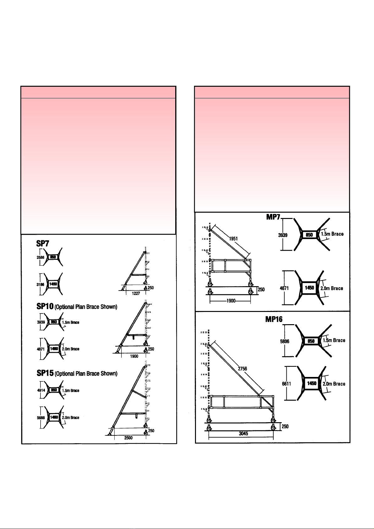
USAGE ADVICE FOR ALL TOWER VARIATIONS

STABILITY: STABILISERS
Attach one stabiliser to each corner of tower at approx. 45 degrees.
If handle on clamp is obstructed from tightening, undo and place
handle on other side of clamp.
Ensure top clamp is positioned immediately under rung casting and
tighten using the handle just enough to hold clamp in position. The
bottom clamp should be positioned as low down as possible (see
diagram). With SP15 position mid clamp and lightly tighten.
Extend telescopic legs until rubber foot is in contact with ground.
Lock telescopic leg with interlock clip. If Plan Bracing is desired clip
braces(green) from tower to stabilisers at each end of tower as
shown. Ensure rubber feet are in firm contact with the ground by
sliding lower clamp downwards and tighten securely.
Securely tighten top clamp (and mid clamp on SP15’s) to provide a
rigid base structure.
When moving tower lock each telescopic leg just clear of the
ground, unlock castors ensuring area is firm and clear of all
obstructions both on the ground and above. After moving check all
castors are firmly on the ground and locked, and the tower is
vertical. Re-position stabilisers as above.
MOBILE OUTRIGGERS
Insert adjustable leg/castor assemblies into leg of each outrigger,
lock castors.
Attach one outrigger to each corner of the tower at approx. 45 degrees.
If handle on clamp is obstructed from tightening, undo and place
handle on other side of clamp. Ensure top clamp is positioned
immediately under rung casting and tighten using handle just enough to
hold clamp in position. After adjusting legs until castors are firmly on
the ground, carry out this procedure on lower clamp.
Clip in plan braces from tower to outriggers at each end of tower as
shown. Securely tighten all clamps and double check that all castors
are firmly in contact with the ground and are locked.
When moving the tower unlock all castors, ensure area is firm and clear of
all obstructions both on the ground and above the tower.After moving
ensure tower is vertical and that all castors are firmly on the ground
and locked.

ASSEMBLY GUIDE
BROUGHTON PLAN
1450 LADDERSPAN ALL

LANT HIRE & SALES
ALLOY ACCESS SYSTEM


BROUGHTON PLANT HIRE & SALES
850 LADDERSPAN ALLOY ACCESS SYSTEM
ASSEMBLY GUIDE
Fit Toe Boards now
(See over)


BROUGHTON PLANT HIRE & SALES
1450 3T THROUGH THE TRAP DOOR METHOD
Platform Heights in Metres Frame
1.7 2.2 3.7 4.2 5.7 6.2 7.7 8.2 9.7 10.2 11.7 12.2 2 rung
2.7 4.7 6.7 8.7 10.7 3 rung
1.2 3.2 5.2 7.2 9.2 11.2 4 rung
ASSEMBLY GUIDE
Broughton Plant Recommend, two persons are used
to build Towers. Above 4m height it is essential that
at least two persons are used. Only climb the tower
from the inside.

BROUGHTON PLANT HIRE & SALES
1450 3T THROUGH THE TRAP DOOR METHOD
Fit Toe Boards now
(See over)


BROUGHTON PLANT HIRE & SALES
850 3T THROUGH THE TRAP DOOR METHOD
Platform Heights in Metres Frame
at Base
1.7 2.2 3.7 4.2 5.7 6.2 7.7 8.2 9.7 10.2 11.7 12.2 2 rung
2.7 4.7 6.7 8.7 10.7 3 rung
1.2 3.2 5.2 7.2 9.2 11.2 4 rung
ASSEMBLY GUIDE
Fit Toe Boards now
(See over)


BROUGHTON PLANT HIRE & SALES
1450/250 MULTI-RUNG 3T
THROUGH THE TRAP DOOR METHOD
Platform Heights in Metres Frame
at Base
1.7 2.2 3.7 4.2 5.7 6.2 7.7 8.2 9.7 10.2 11.7 12.2 4 rung
2.7 4.7 6.7 8.7 10.7 6 rung
1.2 3.2 5.2 7.2 9.2 11.2 8 rung
ASSEMBLY GUIDE
Broughton Plant Recommend, two persons are used
to build Towers. Above 4m height it is essential that
at least two persons are used. Only climb the tower
from the inside.

BROUGHTON PLANT HIRE & SALES
1450/250 MULTI-RUNG 3T
THROUGH THE TRAP DOOR METHOD
Fit Toe Boards now
(See over)


BROUGHTON PLANT HIRE & SALES
850/250 MULTI-RUNG 3T
THROUGH THE TRAP DOOR METHOD
ASSEMBLY GUIDE
Fit Toe Boards now
(See over)


BROUGHTON PLANT HIRE & SALES
Unit 10, Trade City,Ashton Road, Romford, Essex RM3 8UJ
TELEPHONE: 01708 383350 FAX: 01708 383359
CHECKLIST
I
NSPECT COMPONENTS PRIOR TO ERECTION
INSPECT TOWER PRIOR TO USE
TOWER UPRIGHT
CASTORS LOCKED/LEGS CORRECTLY ADJUSTED
BRACES & PLATFORM LEVEL
STABILISERS/OUTRIGGERS FITTED AS SPECIFIED
PLATFORMS LOCATED & WINDLOCKS ON
HANDRAILS IN PLACE
TOEBOARDS LOCATED
REFER TO THIS CHECKLIST BEFORE USING EACH TIME
This manual suits for next models
1
Table of contents
Other Broughton Lifting System manuals
Popular Lifting System manuals by other brands

Aqua Creek Products
Aqua Creek Products Scout Excel F-SCTXL manual

Harbor Freight Tools
Harbor Freight Tools PITTSBURGH 56617 Owner's manual & safety instructions

Skyjack
Skyjack 3226 Maintenance & parts manual

Monzana
Monzana Deuba DBWH001 instructions

stellar labs
stellar labs 108-14-32 owner's manual

HALDER
HALDER 22352.0030 quick start guide