AUTEC ALM-6040FL Guide
en/TA-11-ALM-6040/10040FL pag.: 1
USER /
INSTALATION
MANUAL
4-POST HD ISSUED 26-05-04
ALM-6040FL
ALM-10040FL
AUTEC Hefbruggen bv
Industrieterrein IJsselveld, Vlasakker 11, 3417 XT MONTFOORT, The Netherlands
Tel: +31 348 477000 Fax: +31 348 475104 Internet: www.autec.nl - E-mail: [email protected]
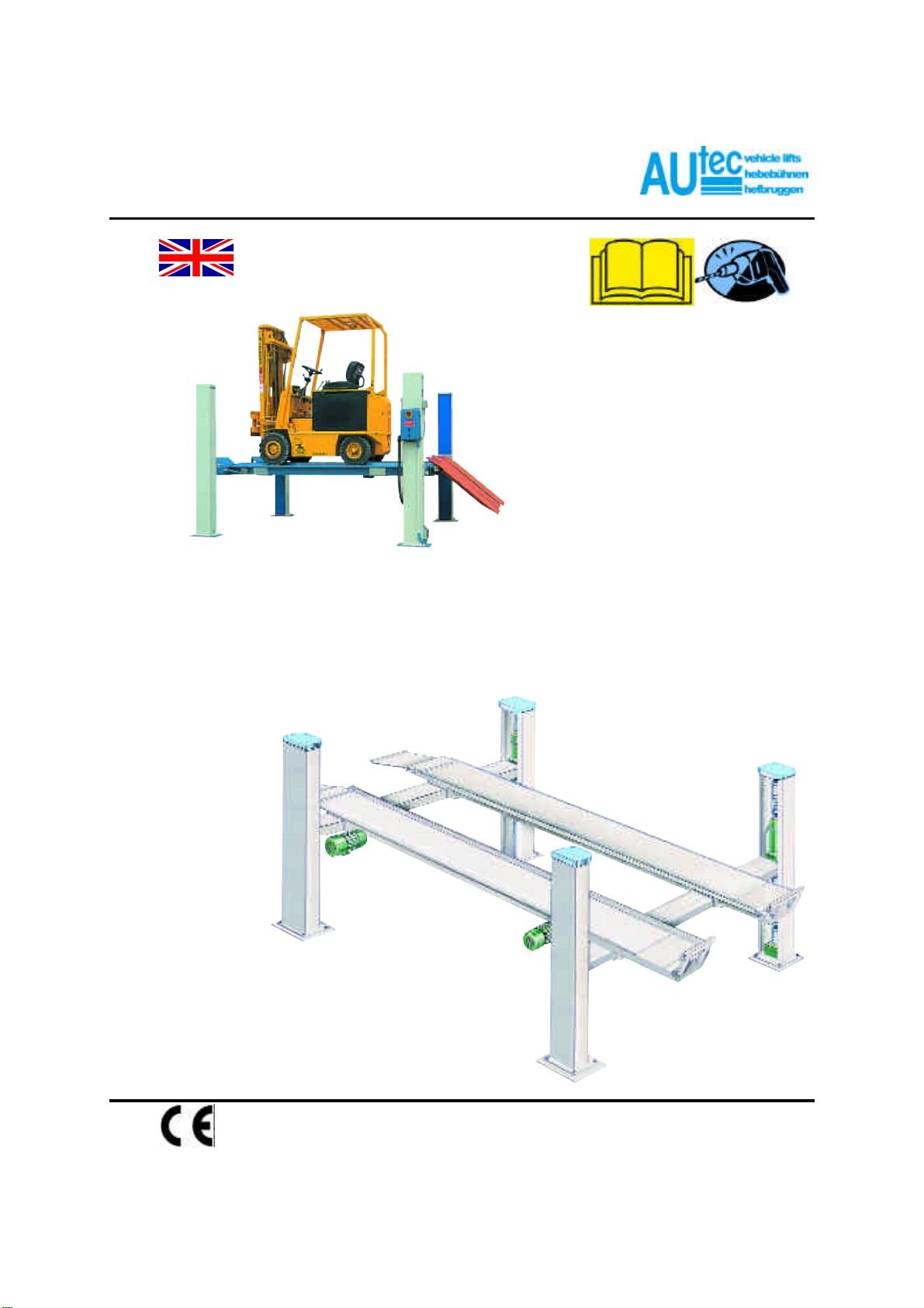
=ELECTRO-MECHANICAL FOUR POST LIFT

en/TA-11-ALM-6040/10040FL pag.: 2
USER /
INSTALATION
MANUAL
4-POST HD ISSUED 26-05-04
ALM-6040FL
ALM-10040FL
AUTEC Hefbruggen bv
Industrieterrein IJsselveld, Vlasakker 11, 3417 XT MONTFOORT, The Netherlands
Tel: +31 348 477000 Fax: +31 348 475104 Internet: www.autec.nl - E-mail: [email protected]
Disclaimer Of Warranties And Limitations Of Liabilities
Whilst the staff of Autec - SUN / VLT Equipment have taken due care in the preparation of this manual nothing
contained herein modifies or alters in any way the standard terms and conditions of the Autec purchase, lease
or rental agreement under the terms of which the Equipment to which this manual relates was acquired or
increases in any way Autec - SUN / VLT Equipment liability to the customer or to third parties.
To The Reader
Whilst every effort has been made to ensure that the information contained in this manual is correct, complete
and up-to date Autec - SUN / VLT Equipment reserves the right to change any part of this document at any
time without prior notice
BEFORE OPERATING THIS UNIT, PLEASE READ THIS MANUAL
CAREFULLY, PAYING EXTRA ATTENTION TO THE SAFETY WARNINGS
AND PRECAUTIONS.
Copyright © Autec - SUN / VLT Equipment
Autec - SUN / VLT Equipment
A division of AUTEC Carlifts bv
Industrieterrein IJsselveld
Vlasakker 11
3417 XT Montfoort
The Netherlands
Tel : 31-(0)348 477000
Fax: 31-(0)348 475104
http://www.autec.nl

en/TA-11-ALM-6040/10040FL pag.: 3
USER /
INSTALATION
MANUAL
4-POST HD ISSUED 26-05-04
ALM-6040FL
ALM-10040FL
AUTEC Hefbruggen bv
Industrieterrein IJsselveld, Vlasakker 11, 3417 XT MONTFOORT, The Netherlands
Tel: +31 348 477000 Fax: +31 348 475104 Internet: www.autec.nl - E-mail: [email protected]
CONTENTS PAG
1. GENERAL INFORMATION 05
1.1 lntroduction 05
1.2 Use of this manual 05
1.3 Contained in this manual 05
1.4 Safety 05
2SAFETY PRECAUTIONS 06
2.1 Safety Notice 06
2.2 General 06
2.3 General Warnings 06
2.4 The weight of the vehicle 08
2.5 Pictograms on lift 08
3SAFETY DEVICES 09
3.1 General precautions 09
3.2 "Dead man" system 10
3.3 Safety device in the presence of obstacles 10
3.4 Mechanical block 10
3.2 Risk of damage due to electricity 11
3.3 Risk and protective media 11
3.4 Hazards associated with lifting of a vehicle 11
3.5 Risk for persons 11
3.5.1 Risk for the operator. 11
3.5.2 Risk for personnel. 12
3.5.3 Risk for impact. 12
3.5.4 Risk for sliding out. 13
3.5.5 Risk for electrocution. 13
3.5.6 Risk due to insufficient lighting. 13
3.5.7 Risk of use/maintenance. 13
3.6 Suitability for usa. 13
4PACKING, TRANSPORT AND STORAGE 15
4.1 Lift handling and pre-installation 15
4.2 Lifting and moving the packing 15
4.3 Storage 15
4.3 Opening the crates and boxes 15
4.4 Product Identification 16
4.5 Warranty 16
4.6 Servicing 16
4.7 Technical Specification 16
5DESCRIPTION OF THE LIFT 18
5.1 Commands 18
6. CHECKING THE MINIMUM REQUIREMENTS FOR THE PLACE OF INSTALLATION 20

en/TA-11-ALM-6040/10040FL pag.: 4
USER /
INSTALATION
MANUAL
4-POST HD ISSUED 26-05-04
ALM-6040FL
ALM-10040FL
AUTEC Hefbruggen bv
Industrieterrein IJsselveld, Vlasakker 11, 3417 XT MONTFOORT, The Netherlands
Tel: +31 348 477000 Fax: +31 348 475104 Internet: www.autec.nl - E-mail: [email protected]
CONTENTS PAG
7. INSTALLATION 20
7.1 Checking the minimum requirements for the place of installation. 20
7.2 Assembling. 21
7.3 Adjustment of the device controlling the wear of the support screw 27
7.4 Obstacle microswitch adjustment 29
8. INSTRUCTIONS FOR USE OF THE LIFT 30
8.1 IMPROPER USE OF THE LIFT 31
8.2 USE OF ACCESSORIES 31
8.3 STAFF TRAINING 31
8.4 IMPORTANT CHECKS TO BE MADE 31
9. MAINTENANCE INSTRUCTIONS 32
9.1 Motor chains 32
9.2 Containers at post base 32
9.3 Gear boxes 33
9.4 Angular transmissions 33
9.5 Checking the wear on the load-bearing support screws 33
10 PROBLEMS 35
11. STORAGE 35
11.1 SCRAPPING 35
12 ELECTRICAL INSTALLATION 36
13 CONFORMITY 37

en/TA-11-ALM-6040/10040FL pag.: 5
USER /
INSTALATION
MANUAL
4-POST HD ISSUED 26-05-04
ALM-6040FL
ALM-10040FL
AUTEC Hefbruggen bv
Industrieterrein IJsselveld, Vlasakker 11, 3417 XT MONTFOORT, The Netherlands
Tel: +31 348 477000 Fax: +31 348 475104 Internet: www.autec.nl - E-mail: [email protected]
1. GENERAL INFORMATION
1.1 lntroduction
Arrangements for the installation of the lift must be made with the manufacturers or suppliers rep-
resentative.
The lift has been designed and manufactured to the highest standards to give many years of reliable
and safe operation if used and maintained in accordance with the safety, operational and mainte-
nance instructions contained in this manual.
1.2 Use of this manual
This manual is intended for use by workshop technicians in charge of the lift (operators) and routine
maintenance technicians (maintenance operators). The operating instructions are considered to be
an integral part of the machine and must remain with it for the whole of its useful life.
Read every section of this manual carefully before operating the lift since it contains important
information concerning the:
=safety of people
=safety of the lift
=safety of lifted vehicles
GTHE COMPANY IS NOT LIABLE FOR ANY POSSIBLE PROBLEMS, DAMAGE OR ACCIDENTS
ARISING FROM FAILURE TO FOLLOW THE INSTRUCTIONS.
1.3 Contained in this manual
The following is recommended for the proper use of this manual:
=keep the manual in an easily accessible place near the lift;
=keep the manual in an area protected from damp;
=use this manual properly without damaging it
=do not make changes to the manual; changes and updates may only be made by the
manufacturer;
This manual is an integral part of the lift and should be given to the new owner if and when the lift is resold.
1.4 Safety
Every effort has been made to make this lift as safe as possible however, as with all lifting Equipment, it is
important that safe working practices are followed.
General safety information is to be found in the chapter "Safety Precautions" and specific safety warnings and
cautions are printed where applicable this throughout the text. All personnel working with or in the vicinity of
this lift must be familiar with the warnings and cautions contained in this manual.
en/TA-11-ALM-6040/10040FL pag.: 6
USER /
INSTALATION
MANUAL
4-POST HD ISSUED 26-05-04
ALM-6040FL
ALM-10040FL
AUTEC Hefbruggen bv
Industrieterrein IJsselveld, Vlasakker 11, 3417 XT MONTFOORT, The Netherlands
Tel: +31 348 477000 Fax: +31 348 475104 Internet: www.autec.nl - E-mail: [email protected]
2SAFETY PRECAUTIONS
2.1 Safety Notice
GFOR YOUR SAFETY, READ THIS MANUAL AND THE SAFETY PRECAUTIONS THOROUGHLY
BEFORE OPERATING THE LIFT.
GTHE LIFT IS INTENDED FOR USE BY PROPERLY TRAINED PERSONNEL ONLY. THE
SAFETY MESSAGES PRESENTED IN THIS MANUAL ARE INTENDED AS REMINDERS TO
TRAINED OPERATORS TO EXERCISE CARE WHEN USING THE UNIT.
2.2 General
The lift is supplied in a safe condition. In order to keep it in a safe condition and to ensure safe
operation of the Equipment, the operating and maintenance instructions contained in this manual
must be followed and the safety warnings & cautions must be observed.
2.3 General Warnings
General Warnings, giving instructions for the prevention of injury to people, are given in the following list.
Further specific warnings are printed where applicable before the appropriate subject.
GBEFORE USING THE LIFT, MAKE SURE THAT THE MAINS POWER SUPPLY CABLE IS
CONNECTED TO A MAINS POWER SUPPLY OUTLET OF THE CORRECT VOLTAGE WITH A
PROTECTIVE EARTH CONTACT. (REFER SERIAL NUMBER PLATE ON THE UNIT FOR MAINS
POWER REQUIRMENTS). VOLTAGES HIGHER THAN SPECIFIED CAN DAMAGE THE UNIT
AND MAKE IT UNSAFE.
G
THE USE OF MAINS POWER SUPPLY EXTENSION CABLES IS NOT RECOMMENDED.
IF ONE HAS TO BE USED, IT SHOULD HAVE CONDUCTORS WITH A DIAMETER OF
AT LEAST 1.5 mm. AND A PROTECTIVE EARTH CONTACT.
GONLY USE FUSES WITH THE FUSE RATING INDICATED NEAR THE FUSE HOLDER.
THE USE OF INCORRECTLY RATED FUSES CAN DAMAGE THE UNIT OR THE POWER CABLE
AND MAKE THESE ITEMS UNSAFE.
GDO NOT OPERATE THE UNIT BEFORE CONTACTING THE SERVICE CENTRE OF THE
MANUFACTURER/SUPPLIER, WHEN THE UNIT:
=SHOWS VISIBLE DAMAGE.
=FAILS TO OPERATE.
=HAS BEEN SUBJECTED TO PROLONGED STORAGE UNDER UNFAVOURABLE CONDITIONS
=HAS BEEN SUBJECTED TO SEVERE TRANSPORTATION STRESSES.
IT IS POSSIBLE THAT THESE CONDITIONS CAN MAKE THE UNIT UNSAFE.
GONLY USE THE LIFT IF YOU ARE QUALIFIED TO WORK WITH IT.
GKEEP PERSONS AND ANIMALS AWAY FROM THE LIFT WHILST IN OPERATION.
GENSURE THAT THE VEHICLE CANNOT MOVE DURING LIFTING. ALWAYS SET THE GEAR
SELECTOR IN NEUTRAL, SET THE PARKING BRAKE AND PLACE WHEEL CHOCKS IN FRONT
AND AT THE REAR OF THE DRIVE WHEELS BEFORE LIFTING A VEHICLE.
en/TA-11-ALM-6040/10040FL pag.: 7
USER /
INSTALATION
MANUAL
4-POST HD ISSUED 26-05-04
ALM-6040FL
ALM-10040FL
AUTEC Hefbruggen bv
Industrieterrein IJsselveld, Vlasakker 11, 3417 XT MONTFOORT, The Netherlands
Tel: +31 348 477000 Fax: +31 348 475104 Internet: www.autec.nl - E-mail: [email protected]
GTHE LIFT HAS BEEN DESIGNED FOR LIFTING VEHICLES AND HOLDING THEM AT ANY
HEIGHT WITHIN THE WORKING PARAMETERS OF THE MACHINE IN AN ENCLOSED ENVI-
RONMENT. ANY OTHER USE IS FORBIDDEN INCLUDING:
=THE WASHING OF VEHICLES;
=THE LIFTING OF PERSONS OR USE AS SCAFFOLDING;
=EXERTING PRESSURE;
=LOADING.
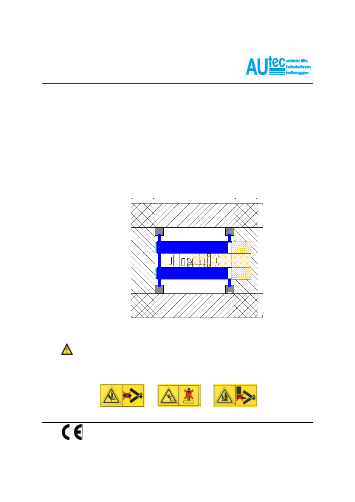
GTHE PRESENCE OF PERSONS INSIDE THE DANGER ZONE (fig. 1) IN THE SAME FIGURE IS
STRICTLY PROHIBITED. THE PRESENCE OF PERSONS BENEATH THE VEHICLE DURING
OPERATIONS IS PERMITTED ONLY WHEN THE VEHICLE IS PARKED IN THE ELEVATED
POSITION.
fig. 1
The safety zone (fig. 1) is to some extend determined by the dimensions of the vehicle to be lifted.
IT IS POSSIBLE THAT THESE CONDITIONS CAN MAKE THE UNIT UNSAFE.
GONLY USE THE LIFT FOR ITS DESIGNED PURPOSE. THE MANUFACTURER SHALL NOT BE
LIABLE FOR ANY INJURY OR DAMAGE TO PEOPLE, VEHICLES OF ANY OTHER OBJECTS
RESULTING FROM IMPROPER OR UNAUTHORISED USE OF THE LIFT.
1000 1000
1000
1000
GONLY USE THE LIFT FOR ITS DESIGNED PURPOSE. THE MANUFACTURER SHALL NOT BE
LIABLE FOR ANY INJURY OR DAMAGE TO PEOPLE, VEHICLES ORANY OTHER OBJECTS
RESULTING FROM IMPROPER OR UNAUTHORISED USE OF THE LIFT
GFOLLOW ALL APPLICABLE HEALTH REGULATIONS AND SAFETY STANDARDS WHEN
WORKING WITH THE LIFT.
2.4 The weight of the vehicle
The maximum loading capacity is not exceeded.
ALM-6040FL MAX. 6.000 Kg.
ALM-10040FL MAX. 10.000 Kg.
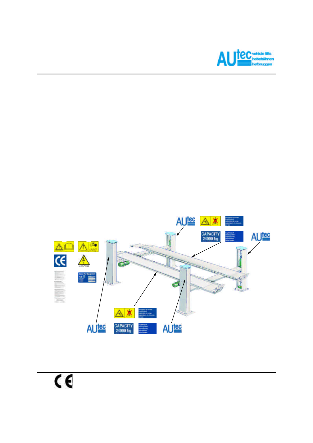
2.5 Pictograms on lift (fig. 2)
IN THE EVENT OF THESE PICTOGRAMS BEING DAMAGED, THEY MUST BE REPLACED BY NEW ONES AVAILABLE
FROM Autec - SUN / VLT Equipment.
1OB904-09 7OB901-ENSKA
3OB904-10 8OB901-DFSP
4OB904 9OB901-24000
5OB905-EDNL 10 OB904-08
6OB903-002 11 OB901-4000
Control unit.
en/TA-11-ALM-6040/10040FL pag.: 8
ISSUED 26-05-04
ALM-6040FL
ALM-10040FL
AUTEC Hefbruggen bv
Industrieterrein IJsselveld, Vlasakker 11, 3417 XT MONTFOORT, The Netherlands
Tel: +31 348 477000 Fax: +31 348 475104 Internet: www.autec.nl - E-mail: [email protected]
11
10 7
9 8
2 1
4 3
5 6
11
11
11
fig. 2
USER /
INSTALATION
MANUAL
4-POST HD
10 7
9 8

en/TA-11-ALM-6040/10040FL pag.: 9
USER /
INSTALATION
MANUAL
4-POST HD ISSUED 26-05-04
ALM-6040FL
ALM-10040FL
AUTEC Hefbruggen bv
Industrieterrein IJsselveld, Vlasakker 11, 3417 XT MONTFOORT, The Netherlands
Tel: +31 348 477000 Fax: +31 348 475104 Internet: www.autec.nl - E-mail: [email protected]
3. SAFETY DEVICES
WARNING:
The lift is designed and constructed to lift vehicles and to hold them in a certain position
in a covered working place. Any other form of use is not permitted. In short, the lift is
not suitable for the following purposes:
=Washing and spraying exersises.
=To be used as a device for applying force.
=To be used as a goods lift.
=To be used as a jack or for lifting vehicles for changing wheels.
The manufacturer hereby refuses any claims for damages arising in connection with injury to
persons or damage to vehicle or other property caused due to incorrect and/or unauthorised use of the lift.
During lifting- and lowering movements, the operator must be within the zone of operation (1), as shown in
fig. 1. The presence of any person in the safety zone (2) is strictly forbidden. The presence of persons under
the vehicle is only permitted if the vehicle is parked and locked in the lifted position.
GUSE THE LIFT ONLY IF ALL THE SAFETY ARRANGEMENTS ARE WORKING PROPERLY. IF
THESE RULES ARE NOT FOLLOWED, SERIOUS INJURY COULD BE CAUSED TO PERSONS AS
WELL AS IRREPARAIBLE DAMAGE TO THE LIFT AND THE VEHICLE ON THE LIFT.
3.1 General precautions:
=The operator is bound to follow the regulations which apply in the country in which these lifts are installed.
In addition, the operator must :
=Always work in the operators area as designated in the manual.
=Never remove the protective guards or dismantle or shut down the mechanical, electrical or other types of
safety arrangements.
=Read the safety regulations relating to the lift and take cognisance of the safety information provided in this
manual.
The following terms have been used in this manual to describe the various types of risk :
DANGER: there is a direct possibility of danger which could lead to serious injury or death.
WARNING:this indicates situations and/or actions which are unsafe and could lead to injuries of various
types except death.
CAUTION:this indicates situations and/or actions, which are unsafe and could lead to light injuries to
persons and/or damage to the lift, the vehicle or other properties.
en/TA-11-ALM-6040/10040FL pag.: 10
USER /
INSTALATION
MANUAL
4-POST HD ISSUED 26-05-04
ALM-6040FL
ALM-10040FL
AUTEC Hefbruggen bv
Industrieterrein IJsselveld, Vlasakker 11, 3417 XT MONTFOORT, The Netherlands
Tel: +31 348 477000 Fax: +31 348 475104 Internet: www.autec.nl - E-mail: [email protected]
3.2 "Dead man" system
The lift is equipped with a system which only operates in the presence of the operator: push-button controlled
rise or descent movements are immediately halted when these buttons are released.
3.3 Safety device in the presence of obstacles
If, during lift descent, an obstacle which resistance is greater than the weight of the moving element, a special
limit switch is activated, causing the lift to halt in any working condition. When the lift is at a halt, the only pos-
sible command is the rise command which enables the obstacle to be removed, followed by the descent com-
mando.
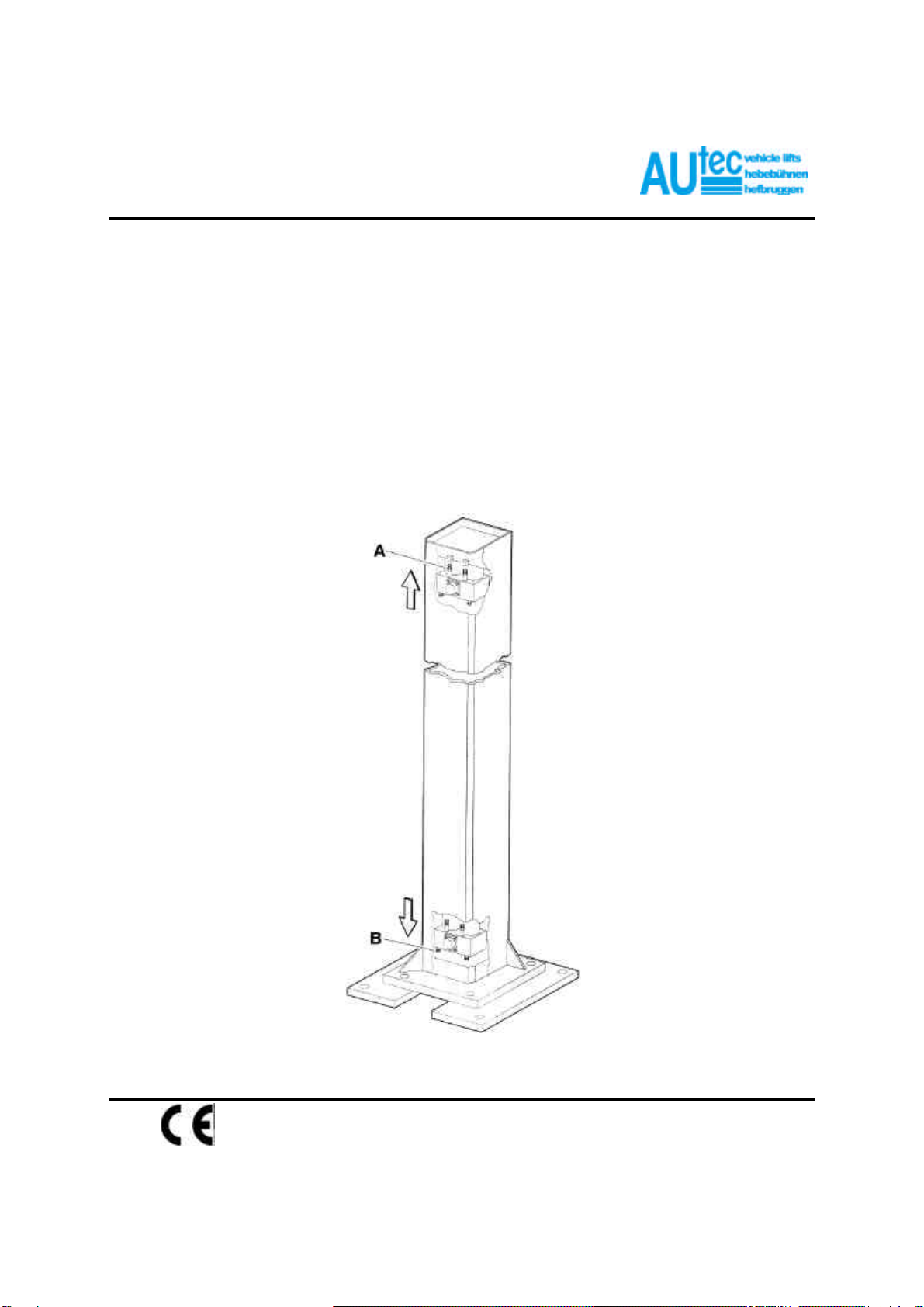
3.4 Mechanical block
This is activated if the rise/descent limit switches do not work.
It is activated during rise (A) and descent (B) after 5 mm runover of the operation point of the limit switch.
Adjust if necessary using the relative adjustment devices.
en/TA-11-ALM-6040/10040FL pag.: 11
USER /
INSTALATION
MANUAL
4-POST HD ISSUED 26-05-04
ALM-6040FL
ALM-10040FL
AUTEC Hefbruggen bv
Industrieterrein IJsselveld, Vlasakker 11, 3417 XT MONTFOORT, The Netherlands
Tel: +31 348 477000 Fax: +31 348 475104 Internet: www.autec.nl - E-mail: [email protected]
3.2 Risk of damage due to electricity
Special safety arrangements have been made on the lift in places where the risks are very high.
3.3 Risk and protective media
The risks to which the operator is exposed when the vehicle is in a raised position, together with the protective
media which have been installed, in order to limit the possible dangers.
3.4 Hazards associated with lifting of a vehicle
The following provisions have been made to avoid damage from excessive weight:
1. Cable break security: in each column a safety bar (catch bar) has been fitted parallel to the cable, which in
the event of the cable breaking will automatically support the raised section
2. Microswitches: microswitches have been fitted to the ends of the crossbeams to control the cable voltage.
Should the voltage to the cable be interrupted, by for example impact with an obstacle during lowering, the
lifting bridge will stop its descent.
3. Leakage and breakage protection: a pipe-breakage valve has been fitted in the cylinder head that will, in
the event of pipe breakage, reduce the rate of descenting of the tracks.
4. Accoustic signal: the lifting bridge will during its descent produce an accoustic signal.
5. Lifting bridge locking: next to the catch bar in each column a locking mechanism has been installed.
This consists of a strip in which grooves have been cut at regular intervals and with them slide locks that
are shot into them by a spring when the raising/lowering button is released.
6. Roll-on and roll-off protection: there is on the front end of the tracks roll-off protection, on the rear side at
the point of entry these are automatically elevated upon lifting.
7. Thermal protection: the electric motor is fitted with thermal protection, which guards the motor from over
heating.
3.5 Risk for persons
This paragraph describes the risks to which the operator or any other person near the working area where the
lift is in operation, in case the lift is not used in the appropriate manner.
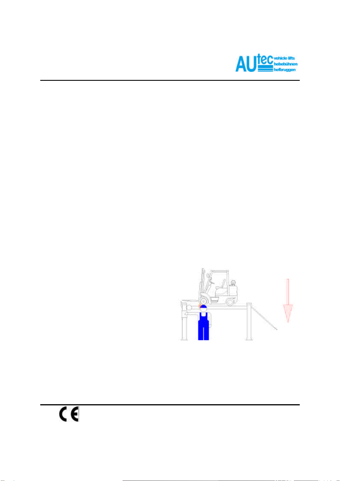
3.5.1 Risk for the operator.
This risk arises in cases where the operator is not
standing at the appointed place at the control
cabinet; when the lift with the vehicle is being low-
ered, it is not permissible for the operator to stand
below the descending system and its load to any
extent. It is imperative that the
operator must be standing in the operating zone
during the lifting and lowering operation. (fig. 3)
fig. 3

en/TA-11-ALM-6040/10040FL pag.: 12
USER /
INSTALATION
MANUAL
4-POST HD ISSUED 26-05-04
ALM-6040FL
ALM-10040FL
AUTEC Hefbruggen bv
Industrieterrein IJsselveld, Vlasakker 11, 3417 XT MONTFOORT, The Netherlands
Tel: +31 348 477000 Fax: +31 348 475104 Internet: www.autec.nl - E-mail: [email protected]
3.5.2 Risk for personnel
When the lift with the vehicle is
moving downwards, it is not per-
mitted for any of the personnel to
enter the room or walk under the
(downwards) moving parts of the
lift.(fig. 4)
The operator should not start the
motion of the lift until he has
assured himself that there are no
persons within the danger zone. fig. 4
3.5.3 Risk for impact
Caused by parts of the lift or the
vehicle that are positioned at head
height. When, due to operational
reasons, the lift is immobilised at
relatively low elevations ( less than
1.75 m from the ground) personnel
must be careful to avoid impact
with parts of the machine not
marked with special hazard
colouring. (fig. 5) fig. 5
Never enter the vehicle or start the
motor when the vehicle is on the lift
(fig.6)
fig. 6
Never rest any fittings or other
objects against the platform
and never place such objects
under the platform when it has
a load mounted on it, since this
can impede the lowering opera-
tions and may cause the vehicle
to fall off the platform (fig. 7)
fig. 7

en/TA-11-ALM-6040/10040FL pag.: 13
USER /
INSTALATION
MANUAL
4-POST HD ISSUED 26-05-04
ALM-6040FL
ALM-10040FL
AUTEC Hefbruggen bv
Industrieterrein IJsselveld, Vlasakker 11, 3417 XT MONTFOORT, The Netherlands
Tel: +31 348 477000 Fax: +31 348 475104 Internet: www.autec.nl - E-mail: [email protected]
3.5.4 Risk for sliding out.
This risk can be overcome by
avoiding the spillage of oil or
grease in the area surroun-
ding the lift (fig. 8).
Apart from that, any oil
spillage which may occur
should be thoroughly removed
from the spot immediately.
Fig. 8
3.5.5 Risk for electrocution.
Never spray water steam, sol-
vents or paint in the area imme-
diately surrounding the platform
and the control cabinet (fig.9)
fig.9
3.5.6 Risk due to insufficient lighting
The area surrounding the lift must be properly lighted according to the legal requirements applicable in the place
of installation.
3.5.7 Risk of use/maintenance
Autec uses material of the highest quality in its lift. These must be used according to the standard specified, and
maintenance must be carried out regularly.
3.6 Suitability for use.
This product has been manufactured in compliance with the European Directive 89/392. On the
basis of article 4.1.2.3 of this Directive, the coefficients used tor the tests are as follows:
1.10 for the dynamic test.
1.25 for the statie test.
These tests must be performed by specialist staff.
Any unauthorized modifications or tampering with the equipment release the manufac-
turer of responsibility for the damages caused by or related to the above men-
tioned acts.
The removal of or tempering with safety devices constitutes an infringement of
European Safety Regulations.

en/TA-11-ALM-6040/10040FL pag.: 14
USER /
INSTALATION
MANUAL
4-POST HD ISSUED 26-05-04
ALM-6040FL
ALM-10040FL
AUTEC Hefbruggen bv
Industrieterrein IJsselveld, Vlasakker 11, 3417 XT MONTFOORT, The Netherlands
Tel: +31 348 477000 Fax: +31 348 475104 Internet: www.autec.nl - E-mail: [email protected]
Place the vehicle in the centre of the footboards.

en/TA-11-ALM-6040/10040FL pag.: 15
USER /
INSTALATION
MANUAL
4-POST HD ISSUED 26-05-04
ALM-6040FL
ALM-10040FL
AUTEC Hefbruggen bv
Industrieterrein IJsselveld, Vlasakker 11, 3417 XT MONTFOORT, The Netherlands
Tel: +31 348 477000 Fax: +31 348 475104 Internet: www.autec.nl - E-mail: [email protected]
4. PACKING, TRANSPORT AND STORAGE
Every action involving the operation, transportation or unpacking of the equipment may only be done by trained
personnel who have a proper knowledge of the lift, and who are familiar with the contents of this operating
manual.
fig. 10
4.1 Lifting and moving the packing
The boxes must be lifted and moved with the help of a fork lift truck or a crane.
The equipment chosen must be capable of lifting and moving the equipment safely, keeping in mind the dimen-
sions of the vehicle, the weight, the centre of gravity and protection of fragile parts.
4.2 Storage
The packed lift must always the placed in a covered area at a temperature between -10 oC and + 40 oC and may
not be exposed to direct sunlight.
4.3 Opening the crates and boxes
Check whether the machine hase been damaged during transportation, and whether all the components as
mentioned in the packing list are physically present.
=avoid sudden bolts and tugs, be careful of uneven surfaces, bumps etc...;
=be extremely careful of exposed parts: obstacles, difficult through ways, etc...;
=wear suitable and protective clothing;
=after having removed the various packings, place them in special waste collecting areas which are inaccessi-
ble to children and animals where they will then be disposed of;
=on arrival, check that the packing has not been opened and, once unpacked check that nothing has been
damaged.

en/TA-11-ALM-6040/10040FL pag.: 16
USER /
INSTALATION
MANUAL
4-POST HD ISSUED 26-05-04
ALM-6040FL
ALM-10040FL
AUTEC Hefbruggen bv
Industrieterrein IJsselveld, Vlasakker 11, 3417 XT MONTFOORT, The Netherlands
Tel: +31 348 477000 Fax: +31 348 475104 Internet: www.autec.nl - E-mail: [email protected]
4.4 Product Identification
The identification data of the machine are shown in the label placed on the frame of the machine (fig. 11) and
indicated in the declaration of conformity. Use this data both to order spare parts and when getting in touch with
the manufacturer.
fig. 11
THE REMOVAL OF THIS LABEL IS STRICTLY FORBIDDEN.
Machines may be updated or slightly modified in appearance and, as a consequence, may present features
different from those shown without prejudice to what is described on it.
4.5 Warranty
The warranty is valid for a period of 12 months starting from the date of the invoice.
The warranty will be automatically invalidated if unauthorised modifications to the machine or parts there of are
carried out. The Manufacturer's authorised personnel must verify defects in workmanship or materials.
4.6 Servicing
For all servicing and maintenance operations not specified or shown in these instructions, contact the Dealer
where the machine was purchased or the Manufacturer's Commercial Department.
4.7 Technical Specification
X
ALM-6040FL ALM-10040FL
Capacity 6.000 kg 10.000 kg
Lifting time 70 s 80 s
Descent time 70 s 80 s
Noise level 70 dB (A) / 1 m 70 dB (A) / 1 m
Working temp. 0 °C / + 45 °C 0 °C / + 45 °C
Working envir. Indoor Indoor
Motor power 2 X 3 kW 2 X 3 kW
Electr. Supply 400 V / 50 Hz / 3 ph 400 V / 50 Hz / 3 ph
Color RAL 5015 RAL 5015
CE number 390-150X-0028-02-95 390-150X-0029-02-95
Notified body Bureau Veritas Bureau Veritas
en/TA-11-ALM-6040/10040FL pag.: 17
USER /
INSTALATION
MANUAL
4-POST HD ISSUED 26-05-04
ALM-6040FL
ALM-10040FL
AUTEC Hefbruggen bv
Industrieterrein IJsselveld, Vlasakker 11, 3417 XT MONTFOORT, The Netherlands
Tel: +31 348 477000 Fax: +31 348 475104 Internet: www.autec.nl - E-mail: [email protected]
ALM-6040FL
ALM-10040FL
en/TA-11-ALM-6040/10040FL pag.: 18
USER /
INSTALATION
MANUAL
4-POST HD ISSUED 26-05-04
ALM-6040FL
ALM-10040FL
AUTEC Hefbruggen bv
Industrieterrein IJsselveld, Vlasakker 11, 3417 XT MONTFOORT, The Netherlands
Tel: +31 348 477000 Fax: +31 348 475104 Internet: www.autec.nl - E-mail: [email protected]
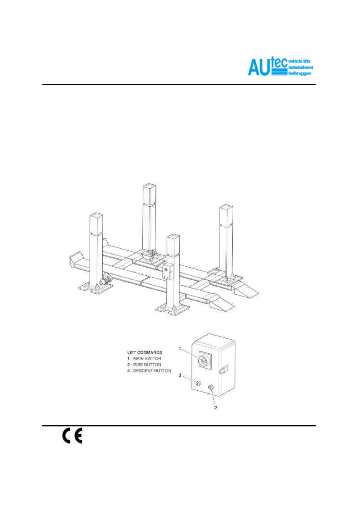
5. DESCRIPTION OF THE LIFT
LIFT Electromechanical four post lift.
Main technical specifications:
=platforms with overhang at both sides for easy motor extraction
=mechanical synchronisation of movements
=irreversible lifting mechanism
=possibility of driving on/down from both sides
5.1 Commands
Command cabinet containing: the hydraulic control box, mains switch, lift rise button, lift descent button and lift
in lockout indicator light.
en/TA-11-ALM-6040/10040FL pag.: 19
USER /
INSTALATION
MANUAL
4-POST HD ISSUED 26-05-04
ALM-6040FL
ALM-10040FL
AUTEC Hefbruggen bv
Industrieterrein IJsselveld, Vlasakker 11, 3417 XT MONTFOORT, The Netherlands
Tel: +31 348 477000 Fax: +31 348 475104 Internet: www.autec.nl - E-mail: [email protected]
6. CHECKING THE MINIMUM REQUIREMENTS FOR THE PLACE OF
INSTALLATION
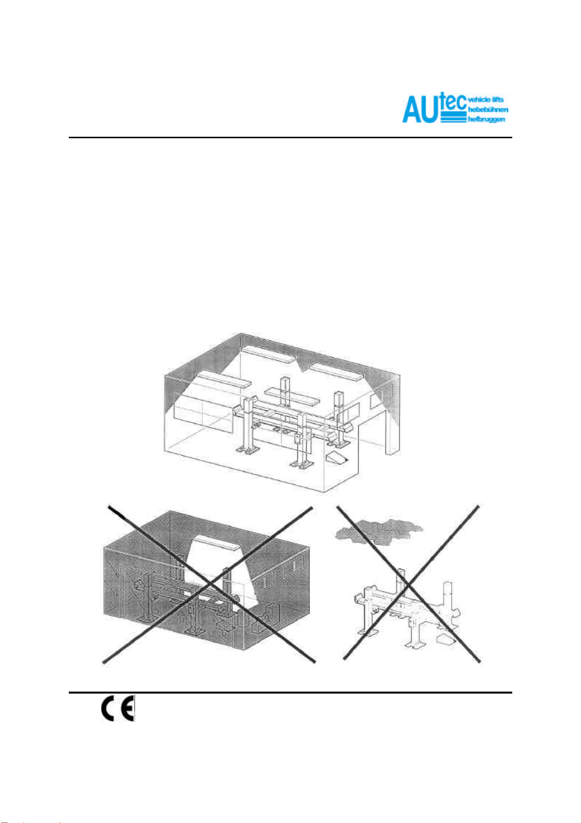
Check that the area in which the machine has to be installed has the tollowing characteristics:
=enough light (without strong or dazzling lighting).
=the area is not exposed to bad weather.
=the area is adequately ventilated.
=an unpolluted environment.
=sound levels are below the prescribed standards required by law
=no dangerous movements are caused in the area by either machines being operated.
=the area in which the machine is installed does not stock explosive, corrosive and/or toxic material.
=the installation layout should be selected so that the operator can see all the equipment and the surrounding
area from the operating position. The operator must prevent unauthorised persons and potentially
dangerous objects from entering this area.
All installation work concerning connections made to external power supplies (particularly electrical) should
be done by professionally qualified staff.
Installation must be done by authorised staff following specific instructions where present in this manual: if
in doubt, please consult authorised service centres or Autec technical services department.

en/TA-11-ALM-6040/10040FL pag.: 20
USER /
INSTALATION
MANUAL
4-POST HD ISSUED 26-05-04
ALM-6040FL
ALM-10040FL
AUTEC Hefbruggen bv
Industrieterrein IJsselveld, Vlasakker 11, 3417 XT MONTFOORT, The Netherlands
Tel: +31 348 477000 Fax: +31 348 475104 Internet: www.autec.nl - E-mail: [email protected]
7. INSTALLATION
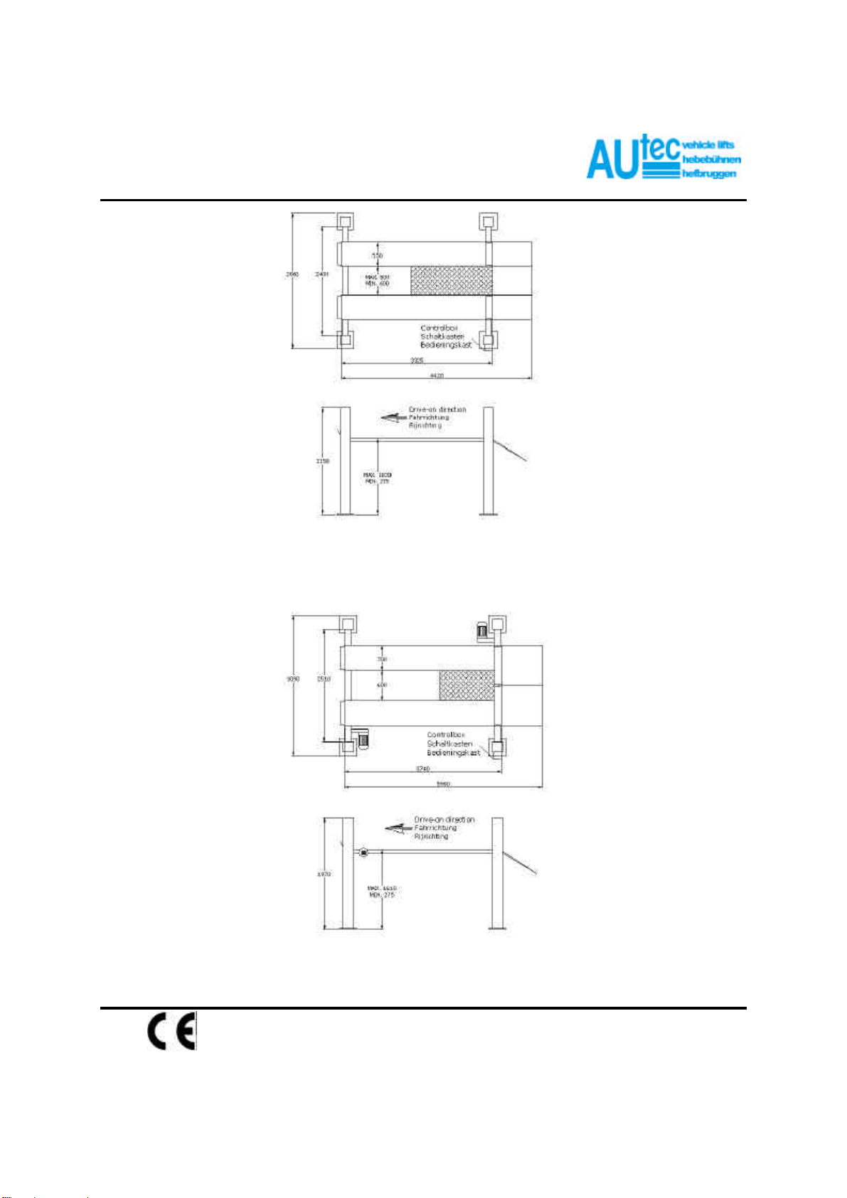
7.1 Preparing the assembling area.
The lift must be placed on an even, compact, resistant floor. If the floor does not meet these requirements,
construct 4 concrete bases (fig. 3) which must be cast at least a week before assembling the lift.
(N.B. Concrete should be R'bk 250 dass or higher with suitable reinforcement).
fig. 12
Cement base measuresMaximum capacity on every post
Cement base measures
This manual suits for next models
1
Table of contents
Other AUTEC Lifting System manuals


