Grandview GPCK-ME500P User manual

Instruction Manual
Recessed-Ceiling
Motorized Projector Lift
Applicable Model
GPCK-ME500P
GPCK-ME1000P
GPCK-ME2000P
GPCK-ME3000P
Cautious
Warnings
Caution Please do not take apart the
accessories of mounting bracket
Do not
take apart
Please read being installation:
Thank you for purchasing this product.
Please read the instruction manual
carefully to ensure this projector lift is
suitable for your installation environment.
This product should only be installed by a qualified technician.
Please review the manual carefully to ensure it is properly installation and to avoid injury.
The ceiling used must have a minimum load bearing of 25KG.
For projector lift assembly only
Maximum weight:
25KG
25KG
25KG
25KG
No.43,Guomao Road South , Hualong Town,Panyu District ,
Guangzhou City ,GuangDong Province,China.
http://www.grandviewscreen.com
Tel:(86)-20-84899499
Guangzhou Grandview Crystal Screen Co.,Ltd.
Guangzhou Grandview Creative Technology Co., Ltd.

WARNING: Important safety instructions.
It is important for the safety of persons to follow these
instructions. Save these instructions.
It is important for the safety of persons to follow these instructions
- For models with fixed control, do not allow children to play with fixed controls.
Keep remote controls away from children;
- Frequently examine the installation for imbalance and signs of wear or damage to
cables and springs. Do not use if repair or adjustment is necessary;
- Do not stand below the product when it is working;
WARNING: Important safety instructions.
Follow all instructions, since incorrect installation can
lead to severe injury.
- Before installing the drive, remove any unnecessary cords and disable any
equipment not needed for powered operation;
- For models with wall switch fixed control, the actuating member of a biased-off
switch is to be located within direct sight of the driven part but away from moving
parts. It is to be installed at a minimum height of 1,5 m; - when projector lift
completely opened, the moving part at least 2.5 m above floor level or other
access level.
Trouble Shooting
The Grandview GPCK-ME is designed for many years of use. Problems are usually caused by small issues or
improper use. If there problems please refer to the follow trouble shooting list. If problems persist, please
contact the authorized dealer or call 020-84899499 for technical support
Limit three year warranty only
Grandview provided limit three year warranty on motorized projector lift products. Grandview's sole obligation under this
warranty shall be to repair or to replace the defective part of the merchandise if the projector lift has been operated properly.
This warranty does not apply to apparatus showing evidence of misuse, abuse or accidental damage, or which has been
installed or operated improperly.
The projector
lift can not
funtion
properly after
installation.
Causes
Power cable is no connected Refering to the user manual and connect the power cable
Outlet does not have power Verify the wall outlet if it has sufficient voltage to support
the operation.
Refering to manual guide and make sure the control
switches are well positioned (up, down, stop)
Control switches have not
been properly positioned
Solution

12
Motor
Front
1
Caution
Warning: In order to minimize the risk of fire or electric shock, do not expose this apparatus to rain or
moisture.
1. Please read the instructions carefully before installation to avoid the damage of the product which
causing by inappropriate installation or operation.
2. Please keep the GPCK-ME away from the hot sources, such as radiator, heating machine, fireplace
and other devices which contain the loudspeaker.
3. This apparatus must be earthed.
4. Only the accessories that provided by the authorized suppliers should be used.
5. Unplug the power cord from the wall outlet during stormy weather or if the apparatus is not used for
several days.
6. Servicing should be done by qualified service personnel.
7. Please do not install this apparatus in the humid area.
8. The apparatus is not disconnected from the AC power source as long as it is connected to the wall
outlet, even if the apparatus itself has been turned off.
9. Use the approved Power Cord (3-core mains lead) / Appliance Connector / Plug with earthing-contacts
that conforms to the safety regulations of each country if applicable.
10. Use the Power Cord (3-core mains lead) /Appliance Connector / Plug conforming to the proper ratings
(Voltage, Ampere).If you have questions on the use of the above Power Cord / Appliance Connector /
Plug, please consult a qualified service personnel.
11. During the installation, incorporate a readily accessible disconnect device in the fixed wiring, or
connect the power plug to an easily accessible socket-outlet near the apparatus. If a fault occurs
during operation of the unit, operate the disconnect device to switch the power supply off, or
disconnect the power plug.
12. The ceiling or wall used for installation must be secure enough; load-bearing capacity must be more
than 4 times of the total weight of this apparatus and the projector in order to prevent the apparatus
from falling.
Cleaning
Please clean the projector and projector lift at the same time.
instruction
To prevent injuries caused
by electric shock, do not
remove any parts. Users
should not checkany internal
parts. Please contact an
authorized technician for any
problems.
Maintenance and Adjustment
1. Please fully retract the project lift after used to avoid the projector exposing to the air and dust, which may
cause the adverse effect on the imaging.
2. Do not roll and retract the projector lift continuously over 4 minutes to avoid overheating. If the motor
continuously work excess 4 minutes, it will be thermally protected and stop working until is has cooled to a
safe temperature before it will start operating again.
3. Lubrication is not necessary for the motor. The drop and retraction limits have been properly adjusted at
the factory (Contact the qualified technician or dealer for the adjustment.)
4. Please clean the projector lift with the dilute detergent slightly and dry it up with the soft cloth. Use the
banister brush to clean the gap.
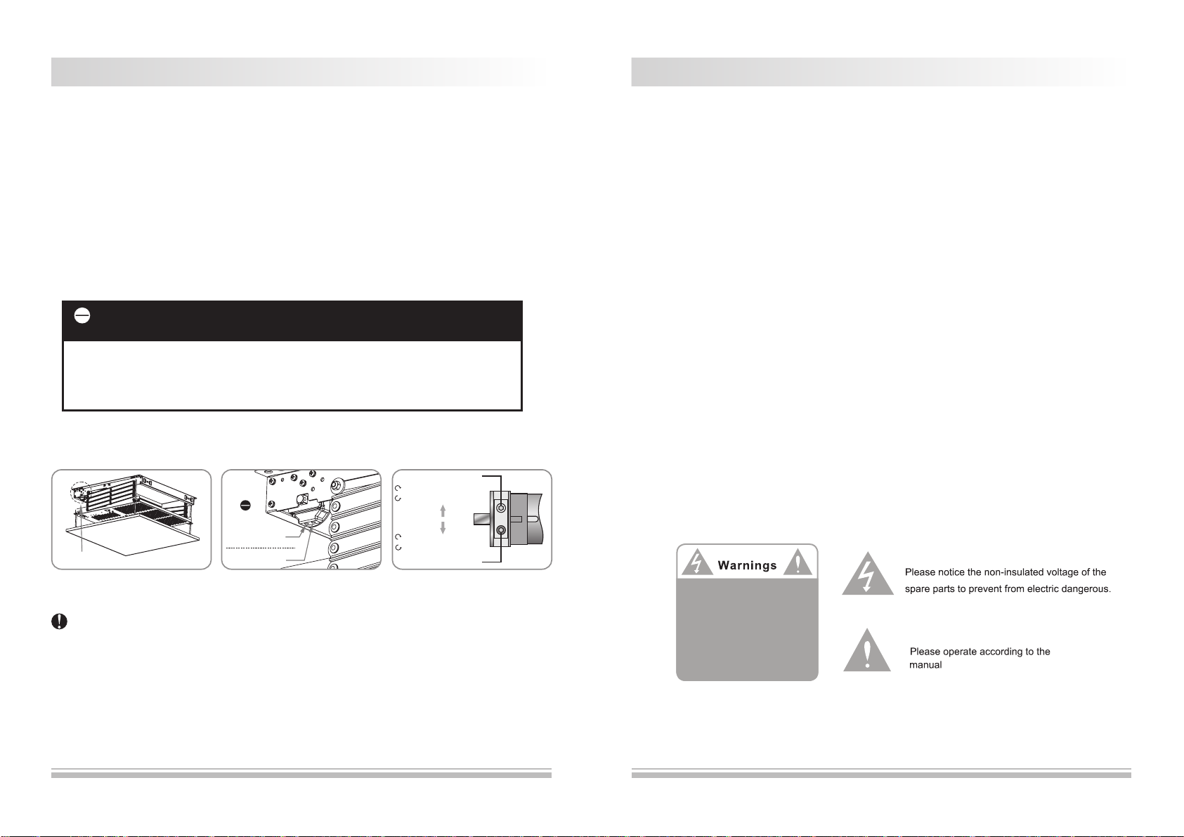
5. The adjustment of the full retraction position (up limit) and full drop position (down limit).
Full drop position (Down limit) adjustment, press "down on the remote control to lower the project lift, insert the
accessory tool into the down limit switch, turning the socket clockwise will stop the projector lift closer to the
ceiling, turning the socket counter-clockwise will cause the projector lift to stop at a lower point.
"
1.Please be careful during adjusting, over up limit adjusting may result in damage to the woven belt and the motor.
2. During the Lowering Limit adjusting, make sure there are more than one and half loops of the woven belt around
the roller to avoid it from breaking off.3.Cheack for satisfactory condition by operating until few times.
Warning
Full drop position
(Down limit)
Turning clockwise, retraction (raising)
Turning counter-clockwise,
drop (lowering)
Full retraction position
(Up limit)
Back
Turning clockwise, retraction (raising)
Turning counter-clockwise,
retraction (raising)
How to Check whether Over up limit adjusting(Retraction)
A. Check the connecting rod on the both end, and see whether no gap between two Rod;
B. The bottom plate can't work.
Figure31 Figure32 Figure33
Limited Setting Hole
Adjustment
Forbidden
UP Limite Adjustment
(Green Hole)
Down Limite
Adjustment(Green Hole)
Prohibition
We strongly suggest that the up limit should not be adjusted by the user in order to
avoid the damages that cause by inappropriate operation.
Full retraction position (Up limit), press"up"on the remote control to raise the project lift, when the
project lift fully retracted and reached the ceiling level, insert the accessory tool into the up limit
switch, turning the socket clockwise will create a lower closed position, turning the socket
counter-clockwise will create a higher, or more fully closed position.

112
Cautions Instruction
Please comply the following contents for installation and use
Please do not shake the projector lift
Forbid Forbid
Please do not lift up the projector lift
Cautions for Location
Please keep away from hot resources, dirty, high temperature and high humidity.
Do not use the projector off the large wind.
Tips
Cautions for Repairing
Please do not take apart the screws of the projector lift;
if this product needs to be repaired, please contact our
company or dealers.
Do not take apart
*In-line Switch with Easy and Steady Operation(Optional), Standard with power plug interface (no power
cable and plug)
*External IR/RF remote control(Optional,External Slot in the back of Lift)(Figure 18 -20)
1.In-Line Switch(Figure25)
(1)Before use the lift, please ensure the lift has been well installated and the decorative ceiling board can
retract smoothly without getting stuck by ceiling.
(2)Connect Power(Rated Voltage)
(3) Press the "Up"and "Down" buttons to lower and Retract the Lift.Press the Stop "0" at any required
postion.
UP
STOP
DOWN
Figure25
2.External IR/RF remote control(Optional)
Please purchase Grandview 3th Generation External IR/RF remote control(Optional) when RS232/485
control required.
(1)Please fix the external Receiver box on the ceiling and ensure close to the lift.
(2) Connecting the receiver box and lift with a Quad Cable(Cable Dia must bigger than 4*0.75mm2,refer
to Figure 28)
(3)For the instruction manual of Receiver box, please refer to single Manual Paper.
Model of External RF remote controller:
External IR Remote Control(3th Generation),Model No.1GD-IRAnIII
External RF Remote Control(3th Generation),Model No.1GD-868MnIII
3. Circuit diagra
AC 110~120V or AC 220V~230V
50~60Hz 170W
m
78m m
1 2 8 m m
Ir Remote
RF Remote
RS232/485
Figure26 Figure27
Figure28
Lift
External Slot 4 Quad Cable
External
Remote control Sets
Supply
Figure29

78mm
128mm
38mm
118mm
310
Installation Accessories
Φ16 Φ5.2 10mm
Optional accessories
max=200mm

4 9
Construction for Projector Lift Installation
8.Choose front or inverted projection direction as required and install the projector accordingly.
Please choose front or inverted installation of projectior accordingly. For front installation,it is
applicable to low ceiling location and requires more than 20mm gap between the projector and lift
which ensures function well of projector lift.
9.Fasten screws to fix the projector onto the multiorifice plate as porjector's slip device.
* This multiorifice plate is universally applicable for most kinds of projectors. Please use multifunctional
arms in case of not corresponding mounting holes between projector and the multiorifice plate. There
are 4units of multifunctional arms in one package and will provide you a flexiable adjustment
installation.
10.Find the signal and power cables in the back of projector then contact the cables through the square
opening at the back buttom of multiorifice plate.
11.The installation board may be unbalanced since the difference of woven belt's tightness or the not
centric barycenter of projector. To keep the installation board balance please adjust the length of
woven belt .( Figure 15)
Left height adjustment( Figure 16), firstly unscrew the left adjusted nut from middle to left, then you
can release or tighten belt by turning left screw. Turning clockwise to release belt and would lower
height of left side. Inversely, turning counterclockwise to tighten belt and upper height of left side.
Right height adjustment( Figure 17), firstly unscrew the right adjusted nut from middle to left, then
you can release or tighten belt by turning right screw. Turning clockwise to release belt and would
lower height of right side. Inversely, turning counterclockwise to tighten belt and upper height of right
side.
Please make sure the adjusted nut after adjustment.
*The woven belt can be adjusted within 20mm, keep lateral balance by adjusting both sides woven belt.
Caution: Decorative ceiling plate can not bear any weights and must be fixed onto the multiorifice plate
by screws, or it may cause product damage even personal casualty.
Figure12 Front installation of projector Figure13 Inverted installation of projector Figure14
Figure15
Balance adjustment
Figure16
GPCK-ME500/1000
Position of unfolding conveyor chain
Motor rack
Motor combo
Left linkage
Conveyor chain
Height adjusting
screw rod
Decorated
ceiling plate
Warning:
Decorated ceiling is only
for decoration use.
Limit positioning
Frame
Installation hole
Undercart belt
Right linkage
Balance adjusting device
Projector mounting plate
Pulley
Front
(Projection direction)
Back
Wire hole
Wire hole
Binding post
Outlet hole
Inlet hole
GPCK-ME2000/3000/4000
Position of unfolding conveyor chain
Loose the belt with clockwise direction
Tighten the belt with anticlockwise direction
Nut
Left
Screw
Right
Figure17
Screw
Nut
Loose the belt with clockwise direction
Tighten the belt with anticlockwise direction

8 5
●
Installation Specification
Specifications
H5
574
514
695
50
H2
15.2
H4
Max. 300
417
567
H1
H3
595
550
15.3
519.4
695
574
550
695
480
520
550
Wire hole
75
130
240 W600xD600x240
350
AC 110V~120V 60Hz or AC 220V~230V 50Hz,Currents:1.4A / 0.74A
25KG
25KG
25KG
25KG
110
165
275
385
GPCK-ME500P
GPCK-ME1000P
GPCK-ME2000P
GPCK-ME3000P

lengthening rod
(Optional
accessories)
H
Screw hook
(Optional
accessories)
6
H
7
Concreted-Ceiling Concreted-Ceiling
Undercart
Undercart
Grille-Ceiling
Grille-Ceiling
Nut Nut
Decorated Ceiling plate
Adjust rod
Adjust rod
H
Instruction
This projector lift needs to be recessed into the ceiling,and this instruction shows us the grille-ceiling
as example. Please install the projector lift according to different application. The projector lift needs to
be recessed at the best viewing angle in order to improve the image. Take out all the parts from the
packaging and follow the accessories guideline to ensure you have all parts.
Please kindly read the instruction manual before installation for safety consideration, and choose the
best installation method according to your site situation.
3.Please stick the locating cardboard on the ceiling,then drill the ceiling by the guide hole of the
cardboard. Then mount the lift and fasten by included M8X80 anchor screws,make sure the lift is fixed.
4.Install the projector lift and fasten.(Figure 7)
2.Pls choose the corresponding installation method according to the product height H1 and the distance
between Roof Surface to Ceiling Surface H.
A.If H<H1(Supposed it's Maximum H2),can install project lift on the Concreted-Ceiling directly
Check Figure 3.
B.If H>H1(Supposed it's Maximum H2),need lengthening bar (Optional accessories)to install
Check Figure 4.
Below use grille-ceiling as example for instruction steps
1, Choose a position according to the required space, and then take apart the ceiling (figure 1). Please
measure the distance H between roof and ceiling surface correctly (figure 2)
Figure 1
Take apart the ceiling
Concreted-Ceiling Roof Surface
Figure 2
Figure3 Standard ceiling installation
Figure 4 High Ceiling
Figure 7
Screw Nut
New Screw Nut
Setscrew
Grille-Ceiling Ceiling Surface
Installation
Figure 5 Distance of Installation Hole Figure 6 Locating Cardboard
(For Drilling hole only)
550
480
520
550
480
520
This manual suits for next models
3
Table of contents
Other Grandview Lifting System manuals
Popular Lifting System manuals by other brands

Bend-Pak
Bend-Pak HDS-14 Installation and operation manual

Bend-Pak
Bend-Pak GP-7LCS Service manual

ARJO HUNTLEIGH
ARJO HUNTLEIGH Alenti Instructions for use

Bend-Pak
Bend-Pak PL-12000DP Installation and operation manual

Bend-Pak
Bend-Pak LR-10000 Installation and operation manual

Bend-Pak
Bend-Pak PL-6000DC Technical service bulletin

SmartMetals
SmartMetals 182.7020 product manual

SmartMetals
SmartMetals 062.7225B product manual

Wesco
Wesco 272467 instruction manual

Bend-Pak
Bend-Pak HD-9ST Installation and operation manual

Alico
Alico Snap-on Equipment EELR571A Installation and operation manual

Bend-Pak
Bend-Pak Turf Maintenance Lift Kit quick start guide