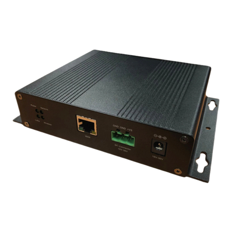
Browan WAPS-232N LW User manual

Browan Communications Inc.
No.15-1, Zhonghua Rd., Hsinchu Industrial Park,
Hukou, Hsinchu, Taiwan, 30352
Tel: +886-3-6006899
Fax: +886-3-5972970
2020 © Browan Communications Inc., All Rights Reserved. This document is for planning purposes only and is not
intended to modify or supplement any specifications or warranties relating to products of Browan Communications.
Browan may make changes to specifications and descriptions at any time, without notice.
WAPS-232N_LW
IOT Access Point
Outdoor Micro Gateway
Installation Guide
Document Number
BQW_02_0016.004

© 2020 BROWAN COMMUNICATIONS INC.
1
Revision History
Revision
Date
Description
.001
May. 12, 2020
Browan first release.
.002
Aug. 7, 2020
Modified Company Address.
Modified Copy Right 2020.
.003
Nov. 20, 2020
Modified specification on page 8, 9(Table 1).
Modified ethernet waterproof connector assembly steps.
.004
Apr. 1, 2022
Modified cover page, add model name for regulatory.
Modification pictures and drawings on page 7.
Updated the mount kit description on page12.

© 2020 BROWAN COMMUNICATIONS INC.
2
Copyright
© 2020 BROWAN COMMUNICATIONS INC.
This document is copyrighted with all rights reserved. No part of this publication may be
reproduced, transmitted, transcribed, stored in a retrieval system, or translated into any language
in any form by any means without the written permission of BROWAN COMMUNICATIONS INC.
Notice
BROWAN COMMUNICATIONS INC. reserves the right to change specifications without prior
notice.
While the information in this manual has been compiled with great care, it may not be deemed
an assurance of product characteristics. BROWAN COMMUNICATIONS INC. shall be liable only to
the degree specified in the terms of sale and delivery.
The reproduction and distribution of the documentation and software supplied with this product
and the use of its contents is subject to written authorization from BROWAN COMMUNICATIONS
INC.
Trademark
The product described in this document is a licensed product of BROWAN COMMUNICATIONS
INC.

© 2020 BROWAN COMMUNICATIONS INC.
3
Contents
REVISION HISTORY...................................................................................................................1
COPYRIGHT..............................................................................................................................2
NOTICE ....................................................................................................................................2
TRADEMARK............................................................................................................................2
CHAPTER 1 BASIC EQUIPMENT ................................................................................................................. 6
1.1 Gateway Installation Diagram ..................................................................................................... 6
1.2 Diagram of Standard Product Equipment ................................................................................... 7
CHAPTER 2 MICRO OUTDOOR GATEWAY SYSTEM INSTALLATION INSTRUCTIONS .............................................. 10
2.1 Exterior Appearance of the Gateway Device: ........................................................................... 10
2.2 Equipment Installation .............................................................................................................. 11
2.2.1 Post Mounting........................................................................................................................ 11
2.2.2 Wall Mounting........................................................................................................................ 15
2.2.3 Assembling and Securing the Waterproof Connector............................................................ 20
2.3 Power......................................................................................................................................... 24
2.4 WAN........................................................................................................................................... 24
CHAPTER 3 GATEWAY INSTALLATION REFERENCE........................................................................................ 25
3.1 Wall-mount Installation............................................................................................................. 26
3.2 Base-mount Installation ............................................................................................................ 32

© 2020 BROWAN COMMUNICATIONS INC.
4
Figures
Figure 1 System Architecture Diagram........................................................................................... 6
Figure 2 Diagram of Standard Product Equipment ........................................................................ 7
Figure 3 Actual View of Standard Equipment ................................................................................ 7
Figure 4 Gateway Front and Rear View........................................................................................ 10
Figure 5 Gateway Installation Instructions................................................................................... 10
Figure 6 Diagram of Equipment Installation Procedures ............................................................. 11
Figure 7 Assembling the Base Frame - Diagram I......................................................................... 13
Figure 8 Assembling the Base Frame - Diagram II........................................................................ 14
Figure 9 Diagram I of Pole Installation ......................................................................................... 14
Figure 10 Diagram II of Pole Installation ...................................................................................... 15
Figure 11 Width between the wall mounting holes..................................................................... 16
Figure 12 Installation Diagram of Wall Mount Anchors (Stainless Steel)..................................... 16
Figure 13 Installation Diagram of Adjustable Plate...................................................................... 17
Figure 14 Assembling Diagram of Base Frame............................................................................. 17
Figure 15 Depiction of Ground Wire ............................................................................................ 18
Figure 16 Installation Completion................................................................................................ 18
Figure 17 Connecting the RF Cable .............................................................................................. 19
Figure 18 Steps for Installation..................................................................................................... 23
Figure 19 PoE Installation Instructions......................................................................................... 24
Figure 20 Sim card installation ..................................................................................................... 24
Figure 21 Actual View of a Wall-mount Installation .................................................................... 26
Figure 22 Wall-mount Installation –Image 1............................................................................... 26
Figure 23 Wall-mount Installation –Image 2............................................................................... 27
Figure 24 The Level....................................................................................................................... 27
Figure 25 Customized Metal Bracket –Image 1 .......................................................................... 28
Figure 26 Customized Metal Bracket –Image 2 .......................................................................... 28
Figure 27 Customized Metal Bracket –Image 3 .......................................................................... 29
Figure 28 Specifications for Customized Metal Bracket –Image 1 ............................................. 29
Figure 29 Specifications for Customized Metal Bracket –Image 2 ............................................. 29
Figure 30 Lightning Protections and Grounding Equipment –Image 1....................................... 30
Figure 31 Lightning Protections and Grounding Equipment –Image 2....................................... 30
Figure 32 6 PVC cable protection hose ........................................................................................ 31
Figure 33 Actual View of a Base-mount Installation.................................................................... 32
Figure 34 Establishing the Base -1................................................................................................ 33
Figure 35 Establishing the Base -2................................................................................................ 33
Figure 36 Establishing the Base -3................................................................................................ 34

© 2020 BROWAN COMMUNICATIONS INC.
5
Tables
Table 1 Device Specifications......................................................................................................... 8
Table 2 List of Gateway Mounting Kit Components .................................................................... 12
Table 3 Description of Gateway Mounting Kit Components ....................................................... 12
Table 4 List of Gateway Mounting Kit Components .................................................................... 15
Table 5 Connecting the RF Cable ................................................................................................. 19

© 2020 BROWAN COMMUNICATIONS INC.
6
Chapter 1 Basic Equipment
1.1 Gateway Installation Diagram
⚫Gateway
⚫Antenna 915MHz*2
⚫Lightning Arrester*2
⚫3G/4G Antenna*1
⚫GPS Antenna*1
⚫PoE
⚫WAN
⚫Power
Figure 1 System Architecture Diagram
RF Cable
Ethernet
Power
Distance at least 100 cm
Antenna
Antenna
Gateway
WA
GPS
Antenna
3G/4G
Antenna
Poe
Input:100-240V
~0.8A 50-60Hz
Output:56V 0.536A
Power
Lightning
Arrester
Lightning
Arrester
3G/4G

© 2020 BROWAN COMMUNICATIONS INC.
7
1.2 Diagram of Standard Product Equipment
NO
TITLE
Q’TY
NO
TITLE
Q’TY
1
WAPS-232N_LW
1
7
RF CABLE (3000 mm)
1
2
PE BAG
1
8
DIPOLE ANT
1
3
GPS ANTENNA
1
9
POWER CORD
1
4
MOUNT KIT ASS’Y
1
10
POE ADAPTER
1
5
EPE HOLDER
1
11
BOX
1
6
RJ45 CONNECTOR
1
12
CARTON (455*375*548 mm)
1/6
Figure 2 Diagram of Standard Product Equipment
Figure 3 Actual View of Standard Equipment
4
3
1
6
7
8
9
10

© 2020 BROWAN COMMUNICATIONS INC.
8
Table 1 Device Specifications
List of Specification Items
No.
Name
Quantity
Remark
Gateway
1
Gateway
(WAPS-232N_LW)
1
⚫Wireless Frequency Band
902 ~ 928MHz ISM (SKU-US)
862 ~ 870MHz ISM (SKU-EU)
470 ~ 510MHz ISM (SKU-CN)
⚫Power input: support 802.3at Power-over-
Ethernet
⚫Transmit Power 0.5W (up to 27 dBm)
⚫Receive Sensitivity -142 dBm
⚫Antenna Type N-Type connected antenna
⚫Operating Temperature -20ºC ~ 60ºC
2
Gateway Protective Pouch
1
3.
GPS Antenna(1.5GHz)
1
⚫Frequency Range :1575.42 ± 1.023 MHz.
⚫Gain: 90°: 5.0 dBi Min.
20°: -2.0 dBi Min.
Mounted on the 60mm*60mm ground plane.
⚫Polarization: RHCP
⚫Axial Ratio: 90°: Max 3.0dB
Mounted on the 60mm*60mm ground plane.
4.
Mount kit
1
Gateway mount kit (accessories included)
5
Gateway Protection Foam
6.
Waterproof Connector
1
RJ45 CABLE CONNECTOR ASS'Y
7.
GPS RF cable
1
3 Meter RF cable (Return loss < -20dB)
8.
3G/4G Antenna
1
⚫Frequency Range
698~960MHz/1710~2700MHz
⚫Average Gain:0~1dBi
⚫Polarization: Vertical Linear
⚫Connector type: N-type
9.
Power code
1
According to country standards
10.
Power over Ethernet
(PoE)
1
⚫Power over Ethernet Output:
Pin Assignment and Polarity:4/5 (+), 7/8 (–)
Output Power Voltage: 55Vdc
User Port Power: 30Watts (Guaranteed)

© 2020 BROWAN COMMUNICATIONS INC.
9
⚫Input Power Requirements:
AC Input Voltage: 100 to 240 Vac
AC Input Current: 0.8A @100-240Vac
AC Frequency: 50 to 60 Hz
⚫Environmental Conditions
Operating Ambient Temperature:
-4ºto 104ºF (-20 to 40ºC) @ 30W
-4ºto 131ºF (-20 to 55ºC) @ 22.5W
Operating Humidity:
Maximum 90%, Non-condensing
Storage Temperature:
-4ºto 158ºF (-20ºto 70ºC)
Storage Humidity:
Maximum 95%, Non-condensing
⚫Regulatory Compliance
IEEE 802.3at (PoE,) RoHS Compliant,
WEEE Compliant, CE
⚫Power cord: connect to PoE
Input/Output:220V
11
Ethernet Cable
(Additional accessories)
2
1 connected to PoE、
1 connected to WAN Cat5e FTP
12
LoRa Antenna
(Additional accessories)
2
⚫N type antenna connectors
⚫LoRa antenna is optional by customer.
⚫Distance between the two antennas must
be at least 100cm
13
Lighting arrester
(Additional accessories)
1
⚫VSWR < 1.5
Note: Additional accessories are not included in the standard package. Please contact Browan
personnel for additional purchases.

© 2020 BROWAN COMMUNICATIONS INC.
10
Chapter 2 Micro Outdoor Gateway System Installation Instructions
2.1 Exterior Appearance of the Gateway Device:
Figure 4 Gateway Front and Rear View
Figure 5 Gateway Installation Instructions

© 2020 BROWAN COMMUNICATIONS INC.
11
2.2 Equipment Installation
Device installation can be physically supported by either post mount or wall mount. Installation
instructions are stated in the following sections and diagrams.
Figure 6 Diagram of Equipment Installation Procedures
2.2.1 Post Mounting
Pre-installation preparations
Please make sure that all required tools and components are available prior to installation.
➢Tools: Allen wrenches (M5 and M8) or an adjustable wrench, Philips screwdriver

© 2020 BROWAN COMMUNICATIONS INC.
12
➢List of components:
Table 2 List of Gateway Mounting Kit Components
CODE
Name of Component
QTY
1
Outdoor Gateway
1
2
Mounting Base Frame
1
3
Adjustable Plate
1
4
Fixing Plate
1
5
Pack of Screws (includes the necessary types of screws)
1
➢Component details as described in the following:
Table 3 Description of Gateway Mounting Kit Components

© 2020 BROWAN COMMUNICATIONS INC.
13
Step 1
Secure the base frame of the mount kit to the Gateway device, as shown in the figure below:
Figure 7 Assembling the Base Frame - Diagram I

© 2020 BROWAN COMMUNICATIONS INC.
14
Step 2
Secure the adjustable plate to the base frame. Please take note NOT to fasten the locking screws
and adjustment screws in a tight manner at this point of installation.
Figure 8 Assembling the Base Frame - Diagram II
Step 3
Install the base frame of the Gateway device against the pole by tightly fastening the fixing plate
to the adjustable plate by using locking screws and adjustable screws. (It is recommended to
install the Ethernet portal downwards.)
Figure 9 Diagram I of Pole Installation
Adjustment Screws
Locking Screws

© 2020 BROWAN COMMUNICATIONS INC.
15
Step 4
The ground wire portal is situated at the corner of the Gateway with an icon. When the
ground wire resistance is less than 5 ohms, the recommended diameter of the ground wire would
be less than 6 mm2.
Figure 10 Diagram II of Pole Installation
2.2.2 Wall Mounting
Pre-installation preparations
Please make sure that all required tools and components are available prior to installation.
➢Tools: Allen wrenches (M5 and M8) or an adjustable wrench, Philips screw, impact drill and drill
bits (the diameter of the drill bit has to be Φ12.7mm), measuring tape 120mm or longer, iron
hammer
➢List of components:
Table 4 List of Gateway Mounting Kit Components
CODE
Name of Component
QTY
1
Outdoor Gateway
1
2
Mounting Base Frame
1
3
Adjustable Plate
1
4
Pack of Screws (includes the necessary types of screws)
1
5
Expansion anchors (stainless steel)
2

© 2020 BROWAN COMMUNICATIONS INC.
16
Step 1: Positioning the wall mounting holes
Mark and drill suitable spots on the wall based on the measurements taken from the mounting
kit. The width between the two mounting holes ought to be 114mm apart and 38.1mm deep by
using a Φ12.7mm drill bit. As shown in the following figure below.
Figure 11 Width between the wall mounting holes
Step 2: Inserting stainless steel anchors
After drilling holes in the wall, insert and drive stainless steel anchors into the holes with a
hammer until they are fully fixed inside the wall.
Figure 12 Installation Diagram of Wall Mount Anchors (Stainless Steel)

© 2020 BROWAN COMMUNICATIONS INC.
17
Step 3: Installing the Adjustable Plate
Fasten the adjustable plate against the wall by securing it with hexagon screws. Figure as
illustrated in the following.
Figure 13 Installation Diagram of Adjustable Plate
Step 4: Assembling the Base Frame and Ground Wire
Secure the base frame of the mount kit to the Gateway with M5x8mm screws and connect the
ground wire. The ground wire portal is situated at the corner of the Gateway with a icon.
Figure 14 Assembling Diagram of Base Frame

© 2020 BROWAN COMMUNICATIONS INC.
18
Figure 15 Depiction of Ground Wire
Step 5: Fastening the Gateway to complete the installation
Match and secure the Gateway base frame against the adjustable plate by inserting M8x50mm
locking screws through the conjoining ends and fasten the screw with nuts. Adjust the Gateway
to the appropriate angle and fasten with M5x35mm adjustable screws to secure the device in
place. Please see the following diagram:
Figure 16 Installation Completion

© 2020 BROWAN COMMUNICATIONS INC.
19
Step 6: Connecting the RF cable
The RF (Radio Frequency) cable is used to connect the antenna and the gateway with a lightning
arrester nested in between.
Note: Install the lightning arrester between the antenna and
the gateway device.
Note: The device could be damaged if no-load power occurs
when the high-power antenna is connected. This type of
damage is not warranted.
Figure 17 Connecting the RF Cable
Table 5 Connecting the RF Cable
1
RF cable type N connector
3
Lightning arrester
2
Lightning arrester ground
wire
4
Antenna connector
⚫Steps for installation:
1. Connect one end of the lightning arrester to the antenna connector.
2. Connect the type N connector of the RF cable to the lightning arrester.
Other manuals for WAPS-232N LW
2
This manual suits for next models
1
Table of contents
Other Browan Gateway manuals