BRP 715003701 User manual

SSV KIT - All-Terrain Trunk Cover
Part number (SKU) : 715003701
Product: Side-by-side
Project no: 487802178
Instruction Sheet P/N: 487802178
Revision no:
Revision date:
Item covered: All-Terrain Trunk Cover
The following symbols may be used in this document:
WARNING
Indicates a hazardous situation which, if not avoided, could result in death or serious injury.
CAUTION: Indicates a hazard situation which, if not avoided, could result in minor or moderate injury.
NOTICE Indicates an instruction which, if not followed, could severely damage vehicle components or other property.
WARNING
- This kit is designed for specific applicable models only (authorized BRP dealers will confirm model(s)). It is not recommended
for units other than the one (those) for which it was sold.
- If the installation of the kit requires a template, ensure template is to scale.
- Should removal of a locking device (e.g. lock tabs, self-locking fasteners, etc.) be required when undergoing disassembly/
assembly, always replace with a new one.
- Torque wrench tightening specifications must strictly be adhered to.
WARNING
GRADE
5.8 8.8 10.9 12.9
M4 1.8 ± 0.2 N•m (16 ± 2 lbf•in) 2.8 ± 0.2 N•m (25 ± 2 lbf•in) 3.8 ± 0.2 N•m (34 ± 2 lbf•in)4.5 ± 0.5 N•m (40 ± 4
lbf•in)
M5 3.3 ± 0.2 N•m (29 ± 2 lbf•in) 5 ± 0.5 N•m (44 ± 4 lbf•in) 7.8 ± 0.7 N•m (69 ± 6 lbf•in) 9 ± 1 N•m (80 ± 9 lbf•in)
M6 7.5 ± 1 N•m (66 ± 9 lbf•in) 10 ± 2 N•m (89 ± 18 lbf•in)12.8 ± 2.2 N•m (113 ± 19
lbf•in)
16 ± 2 N•m (142 ± 18
lbf•in)
M8 15.3 ± 1.7 N•m (135 ± 15
lbf•in)
24.5 ± 3.5 N•m (18 ± 3
lbf•ft) 31.5 ± 3.5 N•m (23 ± 3 lbf•ft) 40 ± 5 N•m (30 ± 4 lbf•ft)
M10 29 ± 3 N•m (21 ± 2 lbf•ft) 48 ± 6 N•m (35 ± 4 lbf•ft) 61 ± 9 N•m (45 ± 7 lbf•ft) 73 ± 7 N•m (54 ± 5 lbf•ft)
M12 52 ± 6 N•m (38 ± 4 lbf•ft) 85 ± 10 N•m (63 ± 7 lbf•ft) 105 ± 15 N•m (77 ± 11 lbf•ft) 128 ± 17 N•m (94 ± 13
lbf•ft)
M14 85 ± 10 N•m (63 ± 7 lbf•ft) 135 ± 15 N•m (100 ± 11
lbf•ft)
170 ± 20 N•m (125 ± 15
lbf•ft)
200 ± 25 N•m (148 ± 18
lbf•ft)
M16 126 ± 14 N•m (93 ± 10 lbf•ft) 205 ± 25 N•m (151 ± 18
lbf•ft)
255 ± 30 N•m (188 ± 22
lbf•ft)
305 ± 35 N•m (225 ± 26
lbf•ft)
M18 170 ± 20 N•m (125 ± 15 lbf•ft) 273 ± 32 N•m (201 ± 24
lbf•ft)
330 ± 25 N•m (243 ± 18
lbf•ft)
413 ± 47 N•m (305 ± 35
lbf•ft)
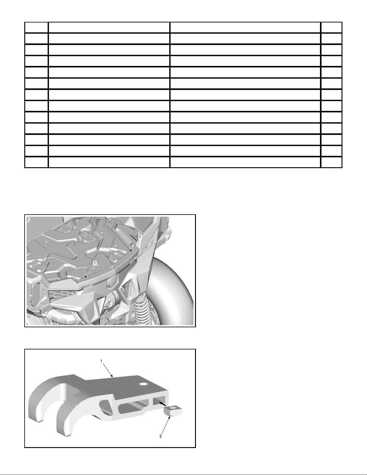
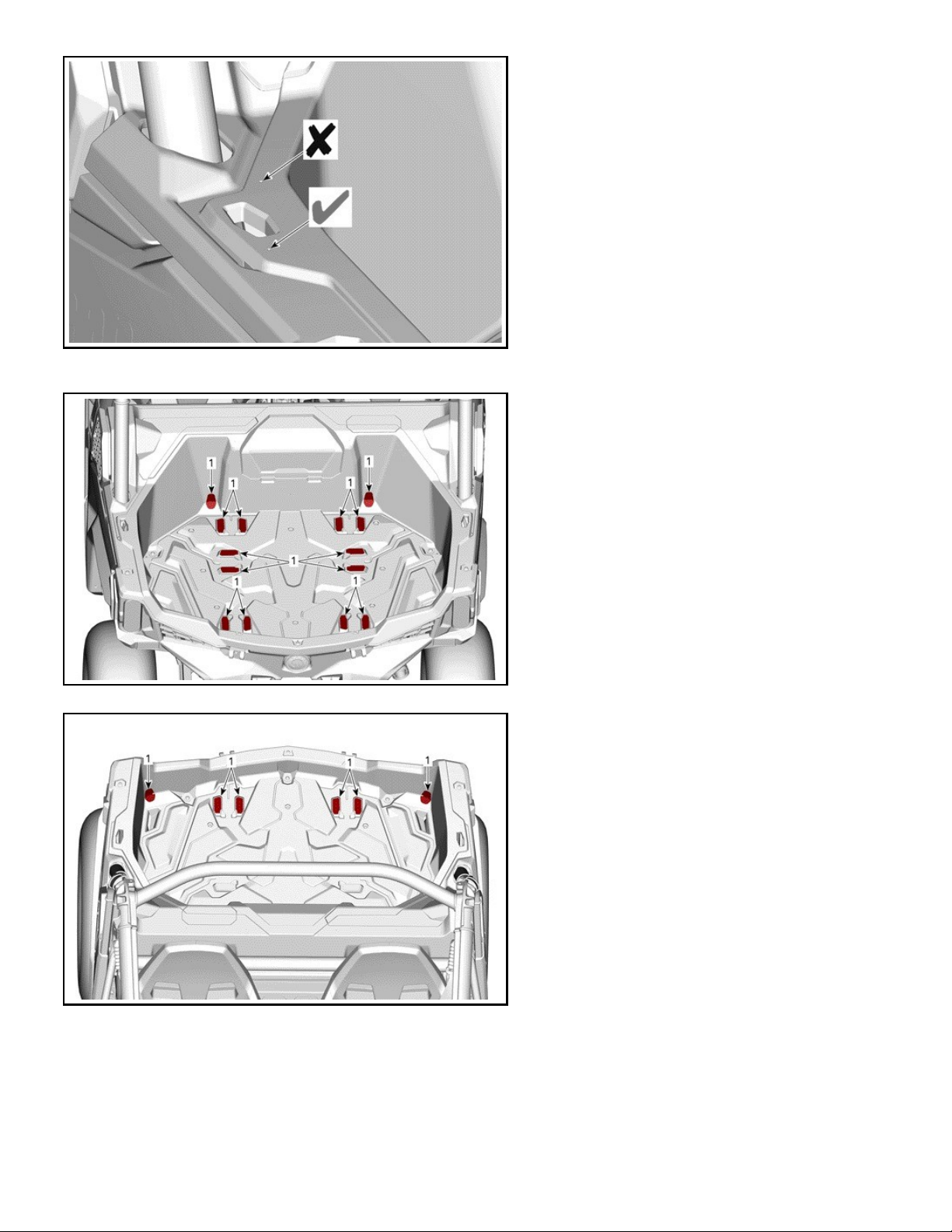
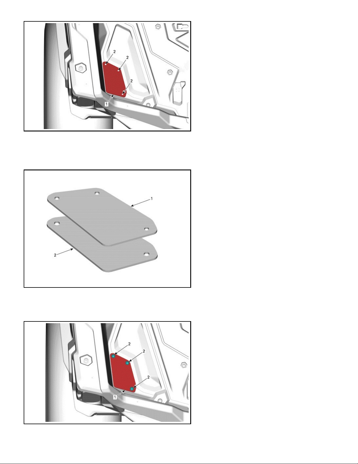
The illustrations in this document show typical construction of the different assemblies and may not reproduce the full detail or exact
shape of the parts; however, they represent parts that have the same or similar function.
about:blank
1 of 15 10/27/2017, 1:15 PM

Installation time is approximately 0.25 hour.
REQUIRED TOOLS
Required Tool Use
T1 Drill bit 5.5 mm (7/32 in) To drill rear cargo
T2 Drill bit 10 mm (13/32 in) To drill rear cargo
T3 Drill bit 3 mm (1/8 in) To drill rear cargo
T4 Drill bit 6 mm (15/64 in) To drill cargo cover
T5 Drill bit 9 mm (23/64 in) To drill rear cargo (only with Cargo Base Kit)
T6 Drill bit 2.5 mm (7/64 in) To drill cargo cover (only with Dome Light Kit)
PARTS TO BE INSTALLED
ITEM DESCRIPTION Part number QTY
P1 Trunk Cover (Not available separately) 1
P2 Machined Hook (Available in service kit (P/N 715004770)) 2
P3 Gas Shock 708302601 1
P4 M6 X 45 Hexagonal Plastic Screw 250000979 8
P5 M8 Flat Washer 250200128 8
P6 M5 Square Nut (Available in service kit (P/N 715004770)) 2
P7 M5 X 45 Screw (Available in service kit (P/N 715004770)) 2
P8 M6 X 45 Hexagonal Screw 250000748 4
P9 Decal Kit (Not illustrated) (Available in service kit (P/N 715004909)) 1
about:blank
2 of 15 10/27/2017, 1:15 PM

ITEM DESCRIPTION Part number QTY
P1 Trunk Cover (Not available separately) 1
P2 Machined Hook (Available in service kit (P/N 715004770)) 2
P3 Gas Shock 708302601 1
P4 M6 X 45 Hexagonal Plastic Screw 250000979 8
P5 M8 Flat Washer 250200128 8
P6 M5 Square Nut (Available in service kit (P/N 715004770)) 2
P10 Washer 250200140 2
P11 Warning Label (Not illustrated) 704906585 1
P12 Plate (Available in service kit (P/N 715004908)) 2
P13 Seal Plate (Available in service kit (P/N 715004909)) 2
P14 Seal (Available in service kit (P/N 715004909)) 2
P15 K50 X 20 Torx Screw 250000760 6
INSTRUCTIONS
Part Installation
Drill two (2) 5.5 mm (7/32 in) holes into rear cargo using markings.
1. Use drill bit 5.5 mm (7/32 in)[T1]
Insert M5 square nut [P6] inside machined hook [P2] as shown.
about:blank
3 of 15 10/27/2017, 1:15 PM

1. Machined hook [P2]
2. M5 Square nut [P6]
Install machined hook [P2] inside rear cargo using one (1) M5 X 45 screw [P7] and one (1) washer [P10].
1. M5 X 45 Screw [P7]
2. Washer [P10]
3. Machined hook [P2]
Tightening Torque
M5 X 45 screw [P7] 3.25 ± 0.25 N•m (29 ± 2 lbf•in)
Repeat same operation for RH side.
Drill eight (8) 5.5 mm (7/32 in) holes into rear cargo using markings.
NOTICE Drill only 4.5 mm (.177 in) deep with drill bit 5.5 mm (7/32 in)[T1].
NOTE: A piece of tape on the drill bit helps to prevent drilling too deep.
1. Use drill bit 5.5 mm (7/32 in)[T1]
NOTE: Near LinQ hole, only the marking furthest from cage must be drilled.
about:blank
4 of 15 10/27/2017, 1:15 PM

Thoroughly clean and dry surface using isopropyl alcohol, then install decal kit [P9] as shown.
1. Decal kit [P9]
1. Decal kit [P9]
Position seal plate [P13] onto rear cargo.
Drill three (3) 3 mm (1/8 in) holes using seal plate [P13] as a template.
about:blank
5 of 15 10/27/2017, 1:15 PM

LH SIDE
1. Use drill bit 3 mm (1/8 in)[T3]
2. Seal plate [P13]
Repeat same operation for RH side.
Stick seal [P14] behind seal plate [P13].
1. Seal plate [P13]
2. Seal [P14]
Repeat same operation for RH side.
Install the seal [P14] and seal plate [P13] onto rear cargo using three (3) K50 X 20 torx screws [P15]. Tighten to specification.
1. Seal [P14] and LH seal plate [P13]
2. K50 X 20 torx screw [P15]
about:blank
6 of 15 10/27/2017, 1:15 PM

Repeat same operation for RH side.
Tightening Torque
K50 X 20 Torx screws [P15] 2.5 ± 0.5 N•m (22 ± 4 lbf•in)
Lay down trunk cover [P1] onto the top of the rear cargo by aligning the holes of the cargo with the holes of the trunk cover [P1].
NOTICE Be careful not to take off the seals while installing the trunk cover [P1].Make sure seal is securely glued to the
tonneau cover. If not, press on any part that may be unglued. This is just to keep it in place during the installation, it will be
compressed after installation.
1. Trunk cover [P1]
1. M6 X 45 Hexagonal plastic screw [P4]
2. Flat washer [P5]
Open trunk cover [P1].
Install six (6) M6 X 45 hexagonal plastic screws [P4] and flat washers [P5] on both sides of the trunk cover [P1]. Screw to have a
slight contact between the washer and the trunk cover. Do not tighten screws. Trunk cover should still be able to move forward and
back.
about:blank
7 of 15 10/27/2017, 1:15 PM

1. M6 X 45 Hexagonal plastic screw [P4]
2. Flat washer [P5]
Close trunk cover [P1].
NOTE: Rear seal must be sufficiently compressed.
Push the trunk cover towards the front of the vehicle and tighten screws while pushing.
Inspect the seal contour to make sure there is no gap between the trunk cover and the cargo box. Inspect the seal to make sure it is
compressed enough to prevent water from dripping inside.
1. Trunk cover [P1]
2. Inspect seal contour
NOTICE Make sure to push in the center and that the cover is not misaligned.
When properly positioned tighten to specification.
Tightening Torque
M6 X 45 hexagonal plastic screws [P4] 8 ± 1 N•m (71 ± 9 lbf•in)
Open trunk cover [P1].
Assemble gas shock [P3] starting with the side on the fixed part.
about:blank
8 of 15 10/27/2017, 1:15 PM

NOTICE Clip the cylinder side onto the sphere on the lifted cover.
1. Gas shock [P3]
Drill one (1) 10 mm (13/32 in) hole on each side of the rear cargo. It will serve to evacuate the water.
LH SIDE SHOWN
1. Use drill bit 10 mm (13/32 in)[T2]
WARNING
Never place gasoline, flammable or dangerous liquids including container on or in carrier. This can lead to an explosion.
Parts Installation With Accessories
Installation With Cargo Base Kit (860200583)
NOTE: This kit does not come with All-Terrain Trunk Cover Kit.
Install the All-Terrain Trunk Cover Kit normally. It is easier to install this kit before installing the trunk cover on the vehicle.
Drill four (4) 6 mm (15/64 in) holes using marking.
NOTICE Remain as much on the center of the marking so the cylinder does not get damaged.
about:blank
9 of 15 10/27/2017, 1:15 PM

1. Use drill bit 6 mm (15/64 in)[T4]
Install cargo base using four (4) M6 X 45 hexagonal screws [P8] onto holes recently made.
Do not use screws provided with cargo base kit.
1. M6 X 45 Hexagonal screws [P8]
2. Cargo base
Under cargo cover [P1], make sure the two (2) plates [P12] are present and install four (4) inserts.
1. Plates [P12]
2. Inserts.
Tightening Torque
about:blank
10 of 15 10/27/2017, 1:15 PM

Tightening Torque
M6 X 45 hexagonal screw [P8] 7.5 ± 1 N•m (66 ± 9 lbf•in)
Installation With Dome Light Kit (487802608)
NOTE: This kit does not come with All-Terrain Trunk Cover Kit. It is easier to install the dome light before installing the trunk cover on
the vehicle.
NOTICE Always disconnect battery before doing any electrical modifications. Proceed exactly in this specific order:
- Disconnect BLACK cable (-) first.
- Disconnect RED cable (+) after.
- Secure battery by covering poles with isolating material.
Drill one (1) 9 mm (23/64 in) onto rear cargo.
1. Use drill bit 9 mm (23/64 in)[T5]
Refer to appropriate section of the Shop Manual to remove:
- Driver's seat and backrest
- Central console
- Console side panel
Install the ring terminals onto the accessories terminal block. The red wire goes to the positive terminal, while the black wire goes to
the negative terminal.
1. Positive Terminal
2. Negative Terminal
Tightening Torque
Accessory post nuts 3.5 ± 0.5 N•m (31 ± 4 lbf•in)
Route harness in direction of the fuse box behind driver backrest and secure the harness along the way as deemed necessary.
about:blank
11 of 15 10/27/2017, 1:15 PM

1. Harness
2. Locking Ties
1. Harness
NOTE: There is not enough locking ties in the dome light kit for all the routing. Add more locking ties as deemed necessary to secure
adequately.
Lift coolant tank access cover and route the harness until it comes out of the rear bulkhead at right of the coolant tank.
1. Harness
Insert dome light harness into hole previously made and install grommet .
about:blank
12 of 15 10/27/2017, 1:15 PM

1. Harness
2. Grommet
On a table, drill two (2) 2.5 mm (7/64 in) holes onto cargo cover [P1].
NOTICE Drill very gently so the outer wall won't break and the visible part of the cargo cover [P1] won't be damaged.
1. Use drill bit 2.5 mm (7/64 in)[T6]
Drill six (6) 6 mm (15/64 in) holes which will serve to secure harness onto inner side of the cargo box [P1].
NOTICE Drill very gently in order to drill through only one wall and the visible part of the cargo cover [P1] won't be
damaged.
1. Use drill bit 6 mm (15/64 in)[T4]
about:blank
13 of 15 10/27/2017, 1:15 PM

Install dome light with two (2) screws
1. Dome light
2. Screws
Route dome light harness along the groove until the rectangular area. Secure the harness along the way as deemed necessary. Use
the transverse areas to pass locking tie and secure harness. Do not tighten locking ties.
Rectangular area is for the excess harness and to join the connectors.
1. Dome light harness
2. Locking Ties
3. Connectors
Close coolant tank access cover.
Follow normal instruction to install the All-Terrain Trunk Cover Kit.
Inside the cargo cover [P1] joint the connectors at the rectangular area.
Secure all harness and tighten all locking ties.
Reconnect battery.
NOTICE Connect RED cable (+) first then BLACK cable (-) .
Verify lights are functioning properly.
Reinstall all removed parts in the inverse order.
NOTICE Make sure power cable does not come into contact with any sharp edges, mobile parts and hot surfaces
before securing it in place.
SAFETY LABEL
This product comes with the following label containing important safety information.
The label should be considered a permanent part of this product. If the label come off or become hard to read, please contact an
authorized dealer for FREE OF CHARGE replacement.
Any person who intend to use this product should read and understand the information contained on the label before doing so.
about:blank
14 of 15 10/27/2017, 1:15 PM

A French warning label is available in the kit and must be installed in accordance with client preference.
To install the French safety label, do the following:
- Clean the entire original label surface and dry thoroughly.
- Carefully install the French safety label OVER the original label.
about:blank
15 of 15 10/27/2017, 1:15 PM
Table of contents
Other BRP Automobile Accessories manuals