VIA NV-SCHIENENSYSTEM D
BRUCK GMBH & CO.KG
INDUSTRIESTR. 22 • 44628 HERNE
internet http://www.bruck.de
GEBRAUCHSANLEITUNG D
TECHNISCHE DATEN
Beschreibung: Mitteneinspeisung für VIA-Schienen
an Wand und Decke.
Systemspannung: 12 V SELV
max. Belastung: 400 Watt
Material: Messing,
Surface: vernickelt / vergoldet / matt-verchromt
LIEFERUMFANG
1 Mitteneinspeisung, komplett 2teilig
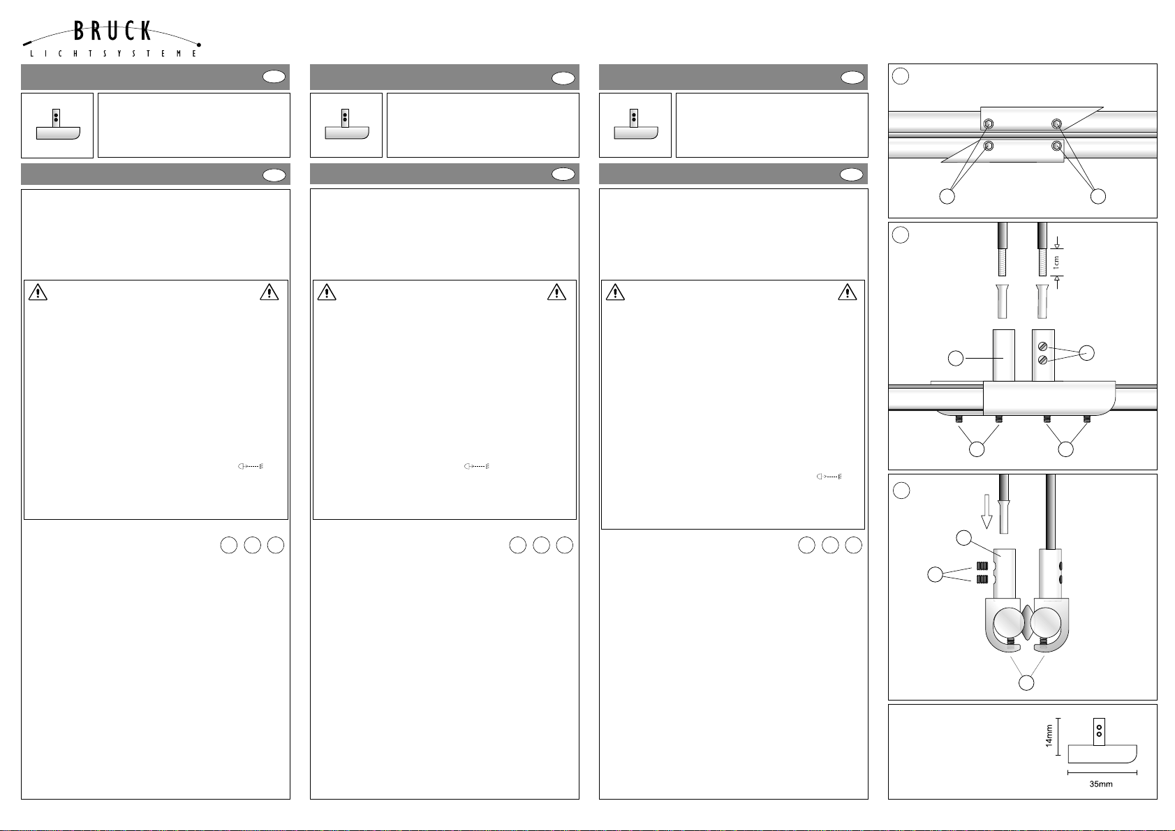
Wichtig! Die Einspeisung kann an beliebiger Stelle der
Schiene nachträglich angebracht werden. Um den
Spannungsabfall zu vermindern, empfiehlt es sich jedoch, den
Ort der Einspeisung möglichst mittig im System zu wählen.
Anschlußleitung min. 4mm², max. 6mm², Kupfer isoliert
- Anschlußleitung 10mm abisolieren (s. Hinweis),
Schrumpfschlauch lose auf das Kabel aufziehen.
- Schrauben Alösen, Einspeisung von der Seite auf die
Schiene schieben. Schrauben Agut anziehen
- Schrauben Blösen, Anschlußleitung mit Aderendhülse
versehen in Bolzen Ceinschieben und Schrauben B
wieder gut festziehen (evtl. mit Schrumpfschlauch isolieren).
Achtung! Bei starker Erwärmung alle Schrauben fest nachziehen!
14 Tage nach Montageende sollten alle Befestigungsschrauben
kontrolliert bzw. leicht nachgezogen werden.
Hinweis: Als Anschlußleitung empfehlen wir unser Produkt
Anschlußleitung, 2 x 4 mm² flexibel, transparent isoliert.
(Art.-Nr.: 150 118 / ID-Nr.: 124 529).
MITTENEINSPEISUNG
ART.-NO. 160 528 ch ID-NO. 298 152
160 528 g 298 169
160 528 mc 298 176
VIA LV TRACK SYSTEM
USER MANUAL
151102993C
GB
GB
ALLGEMEINE SICHERHEITSHINWEISE
1. Montage und Anschluß des Systems nur durch Fachpersonal
(Elektriker).
2. Bei allen Arbeiten an System und Leuchten Anlage
spannungsfrei schalten!!
3. Nicht zur Installation in Feuchträumen geeignet.
4. Bei der Montage des VIA-Systems dürfen nur VIA-System-
bauteile verwendet werden.
5. Achtung, Gefahr durch Stromschlag !! System und Leuchten
niemals ohne Trafo direkt an die Netzspannung anschließen!
6. Es liegt in der Verantwortung des Benutzers, die elektrische,
mechanische und thermische Verträglichkeit zwischen dem
System und den daran angebrachten Leuchten sicherzustellen.
7. Vorsicht! Leuchte und Leuchtmittel werden in Betrieb heiß.
8. Den angegebenen Mindestabstand der Leuchtmittel zu
brennbaren Gegenständen beachten! (siehe Leuchte )
9. Keine Gegenstände über das System hängen:
Kurzschluß und Brandgefahr!
10. Kein Garantieanspruch bei eigenmächtigen Veränderungen
und / oder unsachgemäßer Benutzung!
TECHNICAL DATA
Description: Ceiling power feed for VIA tracks on the
wall and on the ceiling.
System voltage: 12 V SELV
Maximum charge: 400 W
Material: brass,
Surface: chrome-plated / gold-plated / mat chrome-plated
DELIVERY SCOPE
1 central alimentation, complete, one part
Important! The power feed can be built into the track at any
place and at any time later on. But we recommend to choose the
position of the alimentation as centric as possible in the system in
order to avoid a loss of voltage. Connection line, insulated with
copper, minimum 4 qmm, maximum 6 qmm
- Remove 10 mm of the insulation of the connetion line. (See
indication!) Pull the contracting hose slightly onto the cable.
- Loosen the screws A, push the power feed laterally on to the
track. Fix the screws Afirmly.
- Loosen the screws B. Push the connecting line into the bolt C
and insulate it eventually with the contracting hose.
Attention! In case of strong heating, fasten all screws again
firmly! 14 days after finishing the mounting all fixing screws
should be checked or eventually fastened again slightly.
Important! We recommend our product ‘connection line’ as
conducter of connection, 2 x 4 qmm flexible, transparent,
insulated.
(Art.-No.: 150 118 / EAN-No.: 124 529).
GENERAL REMARKS ON SAFETY
1. Assembly and connection of the system only by specialist
personnel (electrician).
2. Switch off power to the system for all work on the system
and on lamps!!
3. Not suitable for installation in wet rooms.
4. For assembly of the VIA system, only VIA system
components must be used.
5. Attention, electric shock hazard!! Never connect the system
and lamps without transformer directly to the mains voltage!!
6. It is within the responsibility of the user to ensure the
electrical, mechanical and thermal compatibility
between the system and lamps mounted to it.
7. Take care! Lamp and illuminant become hot during operation.
8. Observe the stated minimum distance of the illuminants
to flammable objects! ( see lamp )
9. Do not hang objects over the system: Hazard of short
circuit and fire hazard!
10. No warranty claim in case of unauthorized
modifications and / or improper use!
VIA SYSTÈME À RAIL BT
MODE D´EMPLOI
F
F
CARACTÉRISTIQUES TECHNIQUES
Descripcion: Alimentation pour lignes VIA au mur et au
plafond.
Voltage de système: 12 V SELV
Charge max.: 400 W
Matériaux: laiton,
Surface: nickelé / doré / mat-cromé
VOLUME DE LIVRAISON
1 alimentation centrale, complète, une partie
Important! Plus tard, l’alimentation peut être incorporée à la
ligne, à quelconque lieu et à quelconque moment. Mais nous
recommandons d’élégir la position de l’alimentation la plus
centrale que possible au système pour éviter une perte de voltage.
Ligne de connexion, isolée avec cuivre, min. 4 mm², max. 6 mm².
- Enlever 10 mm de l’isolation de la ligne de connexion. (Voir
l’indication!) Passer le tuyau contractant légèrement sur le câble.
- Dévisser les vis A, mettre l’alimentation latéralement à la ligne.
Fixer les vis Atrès fort.
- Dévisser les vis B. Passer la ligne de connexion à la cheville C
et l’isoler éventuellement avec le tuyau contractant.
Attention! Dans le cas d’haute chaleur, fixer encore une fois
très fort toutes les vis! 14 jours depuis de terminer le montage,
tous les vis de fixation devraient être contrôlées ou éventuelle-
ment légèrement serrées de nouveau.
Important! Recommandons notre produit ‘ligne de connexion’
comme conducteur de connexion, 2 x 4 mm² flexible,
transparent, isolé. (Art.-No.: 150 118 / EAN-No.: 124 529).
CONSIGNE DE SECURITE GENERALES
1. Le montage et le raccordement des luminaires ne doivent
se faire que par du personnel spécialisé (électricien).
2. Avant d’effectuer tout travail sur le système et les
luminaires mettre l’installation hors tension.
3. N’est pas approprié à être installé dans des pièces humides.
4. Lors du montage du Système VIA n’utiliser que les
composants de la gamme VIA.
5. Attention danger d’électrocution !! Ne jamais raccorder le système
ou les luminaires directement sur le réseau sans le transformateur !
6. L’utilisateur est resposnsable d’assurer la compatibilité
électrique, mécanique et thermique entre le système et
les luminaires qui s’y rapportent.
7. Attention ! Les luminaires et les lampes sont brûlantes
lors de leur utilisation.
8. Veiller à respecter l’intervalle minimum indiqué des lampes
par rapport à des objets inflammables! (voir luminaires )
9. Ne pas suspendre d’objets au système, danger de court-
circuit et d’incendie !
10. Nous ne donnons aucune garantie lors de modifications
effectuées sur l’installation ou lors d’une utilisation inadéquate
1
3
A
1 2 3
CEILING POWER FEED
ART.-NO. 160 528 ch ID-NO. 298 152
160 528 g 298 169
160 528 mc 298 176
ALIMENTATION DE CENTRALE
ART.-NO. 160 528 ch ID-NO. 298 152
160 528 g 298 169
160 528 mc 298 176
1 2 3 1 2 3
A
CB
2
AA
C
B
A