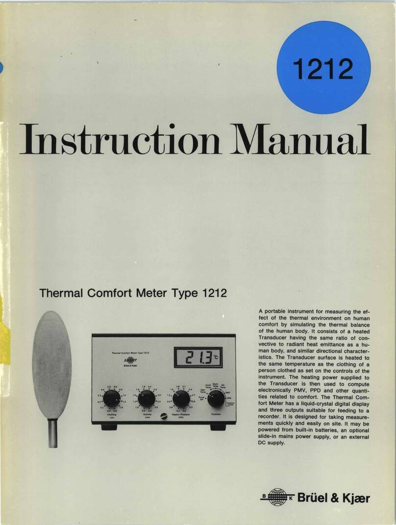
BRUEL & KJAER 4809 User guide
Other BRUEL & KJAER Measuring Instrument manuals
BRUEL & KJAER
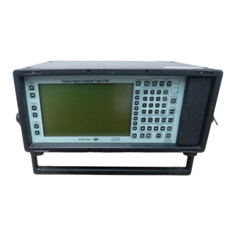
BRUEL & KJAER 2145 Instruction Manual
BRUEL & KJAER
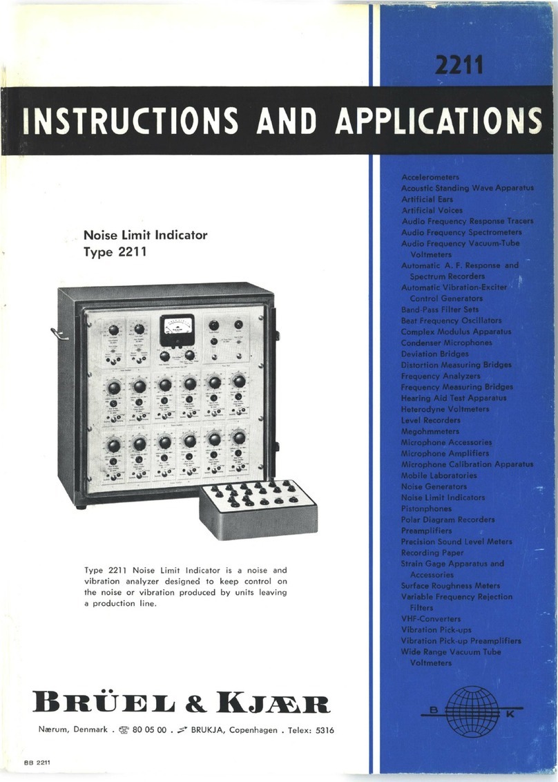
BRUEL & KJAER 2211 User guide
BRUEL & KJAER
BRUEL & KJAER 9737 User manual
BRUEL & KJAER
BRUEL & KJAER 4511-W-006 User manual
BRUEL & KJAER
BRUEL & KJAER 4220 User guide
BRUEL & KJAER
BRUEL & KJAER 1019 Operating instructions
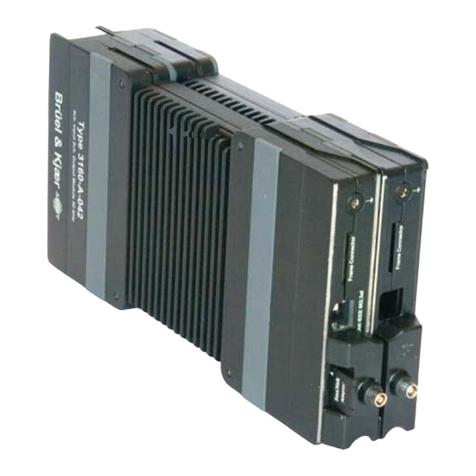
BRUEL & KJAER
BRUEL & KJAER LAN-XI Notar BZ-7848-A User manual
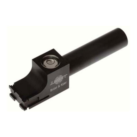
BRUEL & KJAER
BRUEL & KJAER UA-1480 Operating and maintenance manual
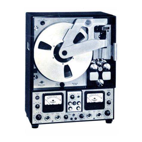
BRUEL & KJAER
BRUEL & KJAER 7001 User guide

BRUEL & KJAER
BRUEL & KJAER 2976 User manual
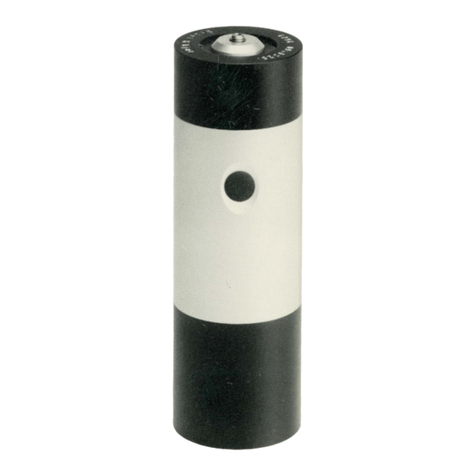
BRUEL & KJAER
BRUEL & KJAER 4294 User manual
BRUEL & KJAER
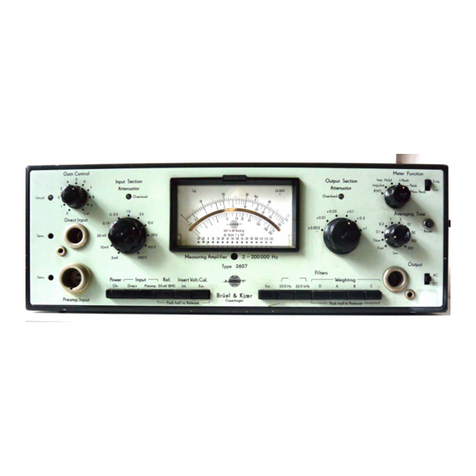
BRUEL & KJAER 2607 User guide
BRUEL & KJAER
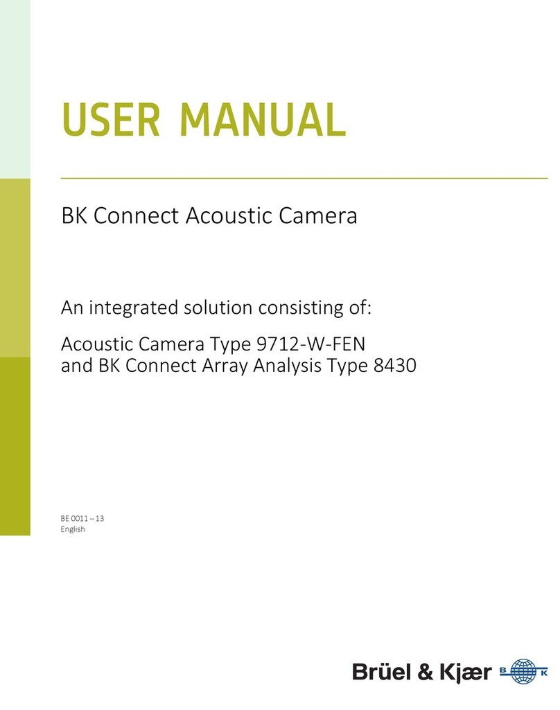
BRUEL & KJAER BK Connect 9712-W-FEN User manual
BRUEL & KJAER
BRUEL & KJAER PULSE 7788 Guide
BRUEL & KJAER
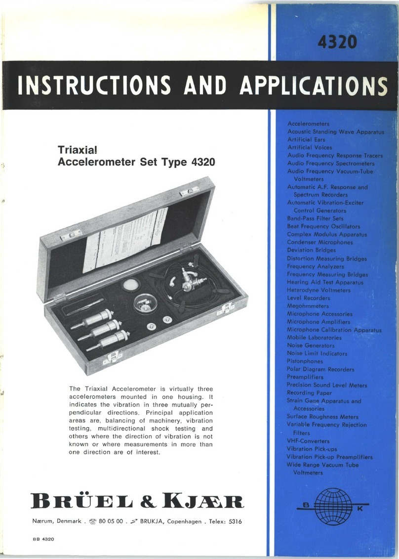
BRUEL & KJAER 4320 User guide
BRUEL & KJAER
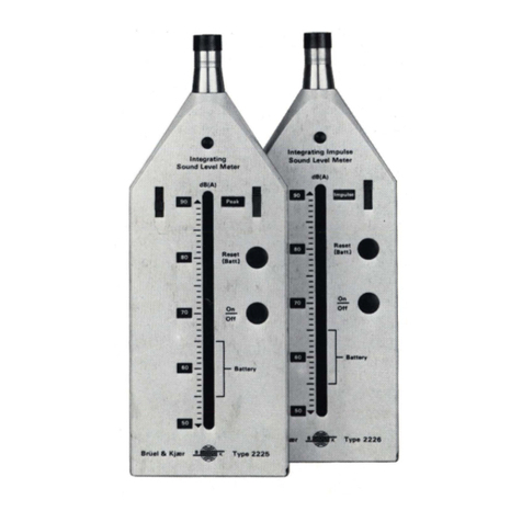
BRUEL & KJAER 2225 User manual
BRUEL & KJAER
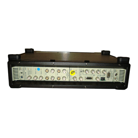
BRUEL & KJAER PULSE 3560-B Guide
BRUEL & KJAER
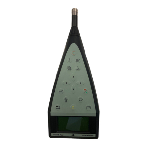
BRUEL & KJAER Mediator 2238 User manual
BRUEL & KJAER
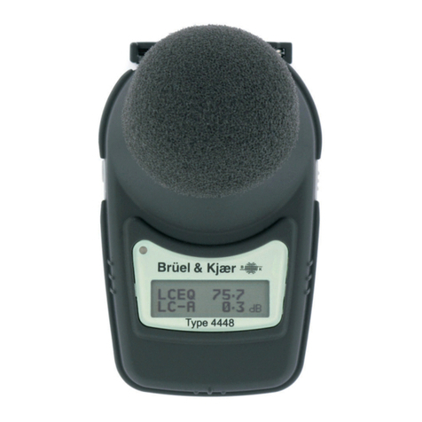
BRUEL & KJAER 4448 User manual
BRUEL & KJAER
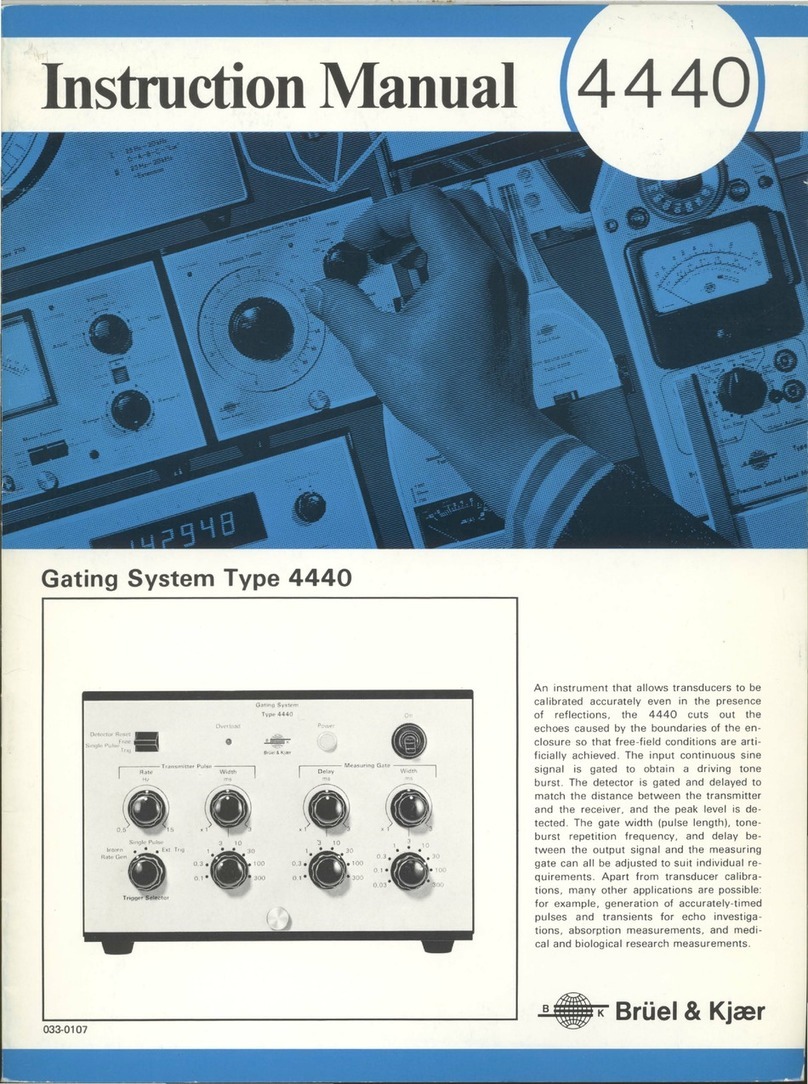
BRUEL & KJAER 4440 User manual
Popular Measuring Instrument manuals by other brands

Powerfix Profi
Powerfix Profi 278296 Operation and safety notes

Test Equipment Depot
Test Equipment Depot GVT-427B user manual

Fieldpiece
Fieldpiece ACH Operator's manual

FLYSURFER
FLYSURFER VIRON3 user manual

GMW
GMW TG uni 1 operating manual

Downeaster
Downeaster Wind & Weather Medallion Series instruction manual

Hanna Instruments
Hanna Instruments HI96725C instruction manual

Nokeval
Nokeval KMR260 quick guide

HOKUYO AUTOMATIC
HOKUYO AUTOMATIC UBG-05LN instruction manual

Fluke
Fluke 96000 Series Operator's manual

Test Products International
Test Products International SP565 user manual

General Sleep
General Sleep Zmachine Insight+ DT-200 Service manual

