BRUNEL JSE1-0129MAEAD User manual

1304 Twin Oaks Street · Wichita Falls, Texas 76302 · (940) 723-7800 · Fax: (940) 723-7888
E-mail: [email protected] · www.brunelcorp.com
World Leader in Modular Torque Limiters
Installation and Maintenance
Instructions
JSE1-0129MAEAD Extruder Clutch

Installation and Maintenance Instructions
JSE1-0129MAEAD Extruder Clutch
1. INSTALLATION
a. Coupling should be installed with pins/buffers removed.
b. Apply an anti-seize compound to the gearbox input shaft.
c. Slide gearbox coupling half (1-23) onto gearbox shaft.
d. Slide motor hub onto shaft.
e. If interference or press fit is specified, heat coupling hub per fit
specified before putting hub onto shaft.
f. Bolt Rigid Hub (1-16) to the Module Carrier Plate (1-19). Using qty.
8, M16 x 65 S.H.C.S. (1-2). Torque tighten to 130 lb ft.
g. Dial indicate coupling Misalignment tolerance: Angular .004”,
Radial .003”. If misalignment is beyond tolerance, realign.
h. Assemble bolts and Buffers with Buffer Bush (1-10) inside of
Buffer (1-9) and a M16 Washer (1-11) on each side of the buffer.
Re-install 14 capscrews (1-12) with loctite on threads. Torque
tighten to 130 lbs.
2. TORQUE ADJUSTMENT & INITIAL STARTUP
a. These torque limiters were preset at the factory, no further
adjustment is required at this time.
b. If it is desired to adjust the release torque at a later date, refer to
#5 “Torque Adjustment”.
3. RESETTING
On overload, the Safety Element Ball is displaced and the Module
Carrier Plate disengages from the Detent Pocket Plate. With the
drive at rest (the power off) and the overload cleared, align the two
reset arrows (or grooves) on the Detent Pocket Plate and Module
Carrier Plate by turning the drive motor shaft by hand. After aligning
the match marks strike the safety element plunger shroud with a soft
mallet and the plunger will move back into the safety element 1/4
inch signifying that the unit is engaged.
DISCONNECTING
To manually disconnect the module, turn the disconnecting nut
(2-21) counter clockwise with a wrench until rotation stops. Modules
are now disconnected and torque limiter is free for checking motor
rotation or for greasing bearing and modules. To re-engage module,
turn disconnecting nut (2-21) clockwise until flush with housing nut
(2-7), then strike plunger shroud (2- 12) with a dead blow mallet.
4. GENERAL MAINTENACE
a. Grease 2-3 pumps from a grease gun into Grease Fitting (2-13)
every 3 months. Recommended grease is “Mobil XTC” - (Modules
Only).
b. Safety elements should be disassembled, inspected and
reassembled at least once every 3 years, more frequently where
frequent tripping occurs.
c. Bearings should be re-greased with Mobil SHC220 every 3
months. Add grease with a grease gun into fitting (1-7) and old
grease is purged from grease relief valve (1-18). Recommended
Bearing Grease: Mobil SHC220
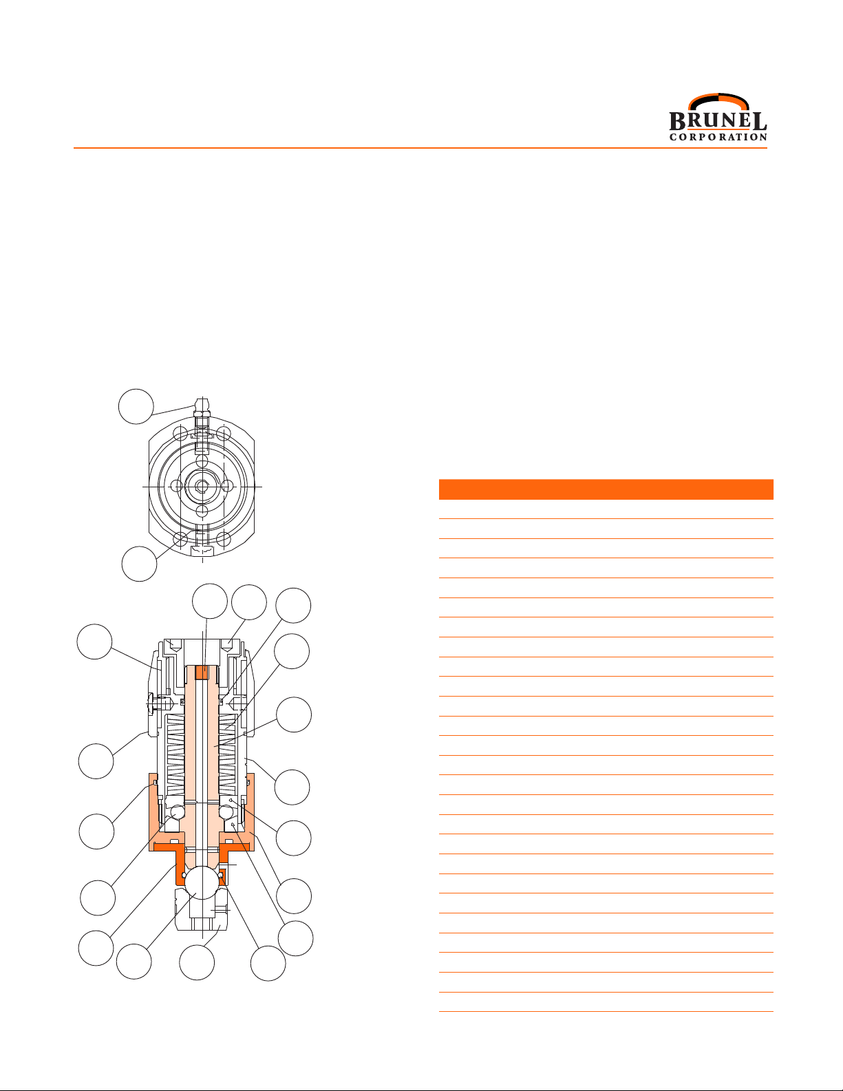
Figure 1
Section view of
Part # JSE1-0129MAEAD
Parts referred to by (Figure # - Part #)
Part No. Description Qty.
1 JSE1 Ext Adj. /Disconnectable 2
2 Capscrew M16 x 65 Skt Hd 8
3 Taper Roller Bearing 2
4 Oilseal 180x150x15 Type R4 1
5 Capscrew M8 x 16 Skt Hd. 1
6 Capscrew M6 x 25 Skt Hd 14
7 Grease Nipple 1
8 JSE1 Thru Hole Fixing Ext. Adj 2
9 Buffer 240 Arnitel, Shore 46D 14
10 Buffer Bush Flanged 240 14
11 Washer M16 Nord-Lock 14
12 Shoulder Bolt 14
13 Grubscrew Mx 3
14 Sensor Segment 2
15 Setscrew M6 x 25 CSK Hd 4
16 Rigid Hub 1
17 Grubscrew 2
18 Pressure Release Valve 1
19 Module Carrier Plate 1
20 Detent Pocket Plate 1
21 Clamp Plate 1
22 Sealing Plate 1
23 Eflex Hub 1
24* Capscrew M6 x 20 Skt Hd 8
25* Blanking Plate 2
26* Flange Blanking Plug 2
27* SE1 Fixing Pack 2
28 Capscrew M6 x 16 SKT HD 6
29 Setscrew M6 x 16 SKT HD IW Point I 4
*Not shown on this view
1

Installation and Maintenance Instructions
JSE1-0129MAEAD Extruder Clutch
5. TORQUE ADJUSTMENT
a. To adjust torque at the job site: Prior to setting Safety Elements
which are new or which have been re-assembled, the desired
release torque for the torque limiter must be known. On the
graph labeled “JSE1-0129AEA Setting Curve” (Page 3) read
the desired release torque on left. Follow across until that point
meets the setting curve and then follow down to the required
setting for each Safety Element. The numbers at the bottom
of the graph refers to the number of setting marks on the
housing of the Safety Element as measured from “zero”. Zero
varies slightly on each safety element and must be determined
independently prior to setting.
b. In order to determine “zero” and set each safety element:
1) Remove security screws (2-15) using special tool and take off
Nut Shield(2-20).
2) Release Set Screw (2-15) in housing (2-11) using special tool.
3) Turn housing nut (2-7) counter-clockwise using socket until
spring force is removed and the housing nut is free to turn by
hand. Now turn the housing by hand clockwise and determine
the point at which resistance is first felt as the springs become
engaged. This is the “zero point”. The number of setting marks
required from the Setting Chart must be counted from this “zero
point”.
4) Using socket wrench, turn housing nut until the required number of
setting marks from “zero” are obtained.
5) Turn Set Screw (2-15) until tight. Re-install Nut Shield using
security screws.
6) Repeat steps 1 through 6 for each safety element.
6. METHOD OF PRELOADING EACH SAFETY ELEMENT (THRU
HOLE DETENT)
(Safety Elements must be preloaded anytime they are mounted onto
assembly) If mounting the safety element (1-1) prior to preloading
follow steps (a) thru (e). If preloading a mounted safety element (1-1),
start with step (f).
9
8
5
17
16
20
21
14,15
13
10 19
4
11
2
7
1
18
3
12
Figure 2
Sectioned View of JSE1-0018
Externally Adjustable Disconnectable
Safety Element
Item Part No. Description Qty.
1 JSE1-0018-1 Plunger 1
2 JSE1-0018-2 Outer Thrust Race 1
3 JSE1-0014-3 Balls (1/4”) 11
4 JSE1-0018-4 Inner Thrust Race 1
5 JSE1-0015-5 Disc Springs 16
6* JSE1-0015-6 Mounting Bolts SHCS 4
7 JSE1-0018-7 Housing Nut 1
8 JSE1-0015-8T Bushing Through Hole 1
9 JSE1-0014-9 Detent Ball 5/8” 1
10 JSE1-0015-10T Detent Pocket 1
11 JSE1-0018-11 Housing 1
12 JSE1-0018-12 Plunger Shroud 1
13 JSE1-0014-13 Grease Fitting 1
14 JSE1-0015-14 Locking Pellet 1
15 JSE1-0015-15 Security Screw 2
16 JSE1-00 15-16 “O” Ring Housing Nut 1
17 JSE1-0014-17 “O” Ring - Housing 1
18 JSE1-0014-13 Grease Fitting 1
19 JSE1-0014-19 Bushing “O” Ring 1
20 JSE1-0018-20 Security Cover 1
21 JSE1-0018-21 Diconnecting Nut 1
22* JSE1-0018-22 Set Screw (locking detent) 1
23* JSE1-0015-23 Flange Plate 1
24* JSE1-0015-24 Lock Nut 1
25* JSE1-0014-25 Set Screw 1
26* JSE1-0015-26 Socket Screw (preload) 1
* Not Shown on This View
2

6. continued
a. Back out set screw (2-22), grease and insert the Detent Pocket
(2-10) into the Detent Pocket Plate (1-20).
b. Grease the bushing (2-8) complete with “O” ring (2-19) and install
over the greased plunger (2-1). Install the greased ball (2-9) in the
hole in the Module Carrier Plate (1-19).
c. Insert the Safety Element assembly (1-1) in to the Module Carrier
Plate (1-19) and securely fix with socket head cap screws (2-6).
Torque tighten to 352 lb.-in.
d. Grease and fit the Flange Plate (2-23), firmly fix to the Coupling
Body by Socket Head Cap Screws (2-26).
e. Insert the Adjusting Screw (2-24) and attach the Locknut (2-25).
f. With a suitable measuring device (such as a dial indicator) placed
on the head of the Plunger (2-1), turn the adjusting screw (2-24)
with a hex wrench until the turning torque suddenly increases
significantly. From this point turn the adjusting screw (2-24) until
.003”-.008” of movement on the Plunger head is achieved, then
lock in position by tightening the Nut (2-25) and Set Screw (2-22).
7. TROUBLE SHOOTING
a. Continual releasing, further adjustment making no difference.
1) Detent Pocket (2-10) worn. Remove Safety Element (1 -1) and
remove Detent Pocket. Rotate Detent 90° and reinstall. If badly
worn replace with new detent pocket.
2) Additional torque capacity is required.
b. Unable to screw Housing Nut (2-7) in any further.
1) Loosen Set Screw (2-15) and make sure that the threads on
the Housing Nut and Housing are not damaged.
If so clean & file burrs until usable or replace defective parts.
2) You have reached maximum torque capacity.
c. Unable to reset.
Reset arrows not aligned. Check reference marks on Module
Carrier (1-19) and Detent Pocket Plate (1-20).
8. SAFETY ELEMENT - METHOD OF ASSEMBLY
a. Clean all components and coat all surfaces with a suitable
anti-seize compound.
b. Grease inside surfaces of the Housing and install Outer
Thrust Race (2-2) and “O” Ring (2-14).
c. Grease Plunger (2-1 ) and install thru Housing and Outer
Thrust Race.
d. Install 11-1/4” Balls (2-3), apply grease over balls.
e. Grease and Install Inner Thrust Race (2-4).
f. Grease inner walls of Housing Nut (2-7).
g. Grease and Install 16 springs (2-5), oriented as shown in
cross section.
h. Screw in the Housing Nut (2-7) into the Housing until there
is contact with the springs (2-5).
i. Insert the Locking Pellet (2-18) and Security Screw (2-
20) into the side of the Housing to facilitate locking the
Housing Nut. (Refer to #2 Torque Adjustment).
j. Grease and insert the ‘’O” Ring (2-19) into the Bushing
(2-8). Insert the Detent Ball (2-9) after throughly greasing
the Bushing ID. Grease the Plunger (2-1) and install the
Bushing.
k. Secure Nut Shield onto Housing Nut (2-7) with Security
Screws (2-20) using special tool provided.
9. JSE1-0129MEAD SETTING CURVE
JSE1-0129MAEAD Setting Curve
Setting of each Safety Element (10 marks per revolution)
RELEASE TORQUE (lb-in)
RELEASE TORQUE vs. SETTING
First Revolution
Set each Module to Mark which corresponds to Required Release Torque
0
5,000
10,000
15,000
20,000
25,000
30,000
35,000
40,000
45,000
50,000
0 2 4 6 8 10 12 14 16 18
3

10. Installation & Maintenance Instructions Eflex Coupling Hubs
1. The following instructions should be read and understood prior to
starting any assembly or maintenance work.
2. Prior to replacing any component, care should be taken to ensure
that it is clean and free from any dirt.
3. Bolts and screws should be tightened evenly, cylinder head
fashion, to 50% torque then to 100% torque in the same
sequence. Where specified it is essential that torque tightening
figures are not exceeded nor should it be allowed for them to be
below specification.
4. To ensure that where hub/shaft connections require a standard
interference fits the hubs may be heated in oil at 135° Celsius
and rapidly positioned on the shaft. It is essential that this heating
is evenly applied over the whole hub and that spot heating is
avoided.
5. Mounting Hubs
Coupling hubs are generally supplied with running or sliding
fits. Therefore axial restraint of the hub should be provided
by set screws when these fits are specified. Steel hubs are
recommended when interference fits are specified, making it
necessary to apply heat to the hubs, preferably in an oil bath or
oven to a max. temperature of 135° C. Mount each hub on their
respective shafts, normally with the face of each hub flush with
the end of its shaft and tighten set screws onto the key, when
supplied.
6. Alignment
Note: Satisfactory alignment can be achieved with the use of
a straight edge and feeler gauge, although a dial indicator or
laser aligning equipment would generally improve accuracy,
independent of geometric component errors.
6.1 Gap and Angular Alignment
Set gap using a spacer bar equal in thickness to the nominal
gap specified in Table 1. With the spacer bar inserted to the
same depth, measure clearance between bar and hub face
at 90° intervals using feelers. Angular alignment should be
as close as possible, the difference between maximum and
minimum measurements should not exceed the angular
limits stated in Table 1.
6.2 Parallel Offset Alignment
Use a straight edge and feelers, or dial indicator over the
coupling outside diameter taking measurements at 90°
intervals. Align as close as possible, error must not exceed
offset limits specified in Table 1. Fit the coupling pins and
flexible elements ensuring that each cap screw has one
washer under its head and one washer on the other side
of the flexible element. Tighten all foundation bolts to
torques specified in Table 1, and repeat steps 6.1 and 6.2. if
necessary, re-align.
7. Maintenance Instructions
Periodically check alignment, check fasteners torques
and check flexible elements for wear to determine if
replacements are required. Excessive misalignment, high
ambient temperatures and / or frequent rapid reversing may
necessitate more frequent inspection.
TABLE 1
Brunel Part No. Coupling Operational Max.
Alignment Limit
Eflex Coupling
Tightening Torque
Rigid Hub
Tightening Torque
Size
or O.D.
(mm)
Gap
Tolerance
(inches)
Gap
Preferred
(inches)
Parallel
(inches)
Angular
(inches) Bolt Size (Ib-ft) Bolt Size (Ib-ft)
JSE.5-0104A 195 0.098 - 0.276 0.187 0.008 0.008 M12 65 M10 40
JSE1-0128A 240 0.098 - 0.276 0.187 0.008 0.010 M16 120 M10 40
JSEI -0129A&B 240 0.098 - 0.276 0.187 0.020 0.020 M16 120 M16 120
JSE2-0241A&B 340 0.118 - 0.354 0.236 0.020 0.020 M20 280 M20 280
JSE2-0243A&B 630 0.118 - 0.354 0.236 0.020 0.030 M30 800 M20 280
4

5

Phone: 940.723.7800
Fax: 940.723.7888
www.brunelcorp.com
1304 Twin Oaks Street
Wichita Falls, TX 76302
Publication: JSE1-0129MAEAD 6-10
Table of contents
Other BRUNEL Industrial Equipment manuals