Installation and Maintenance Instructions
JSE.5-0104MAEAD Extruder Clutch
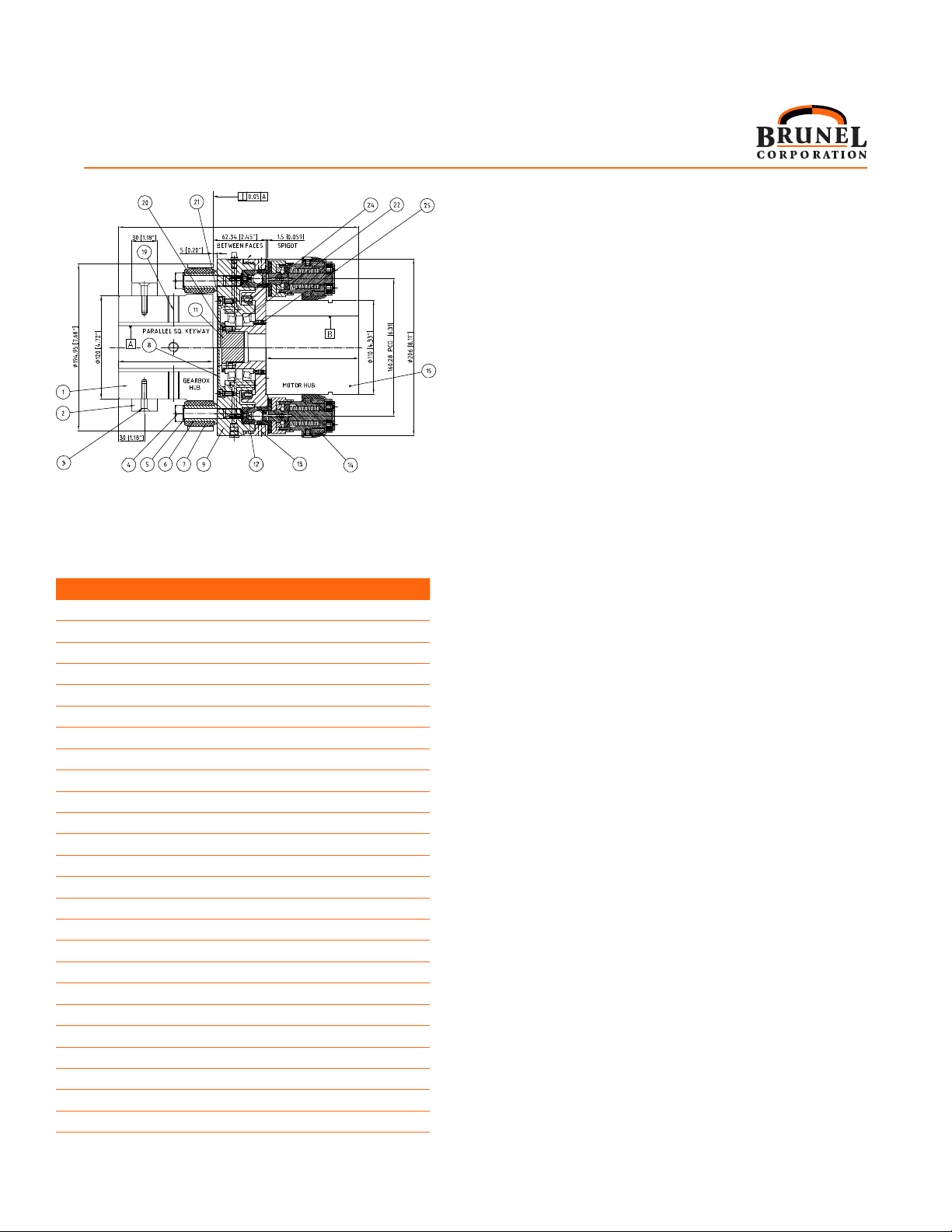
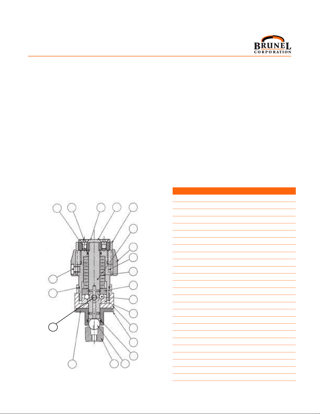
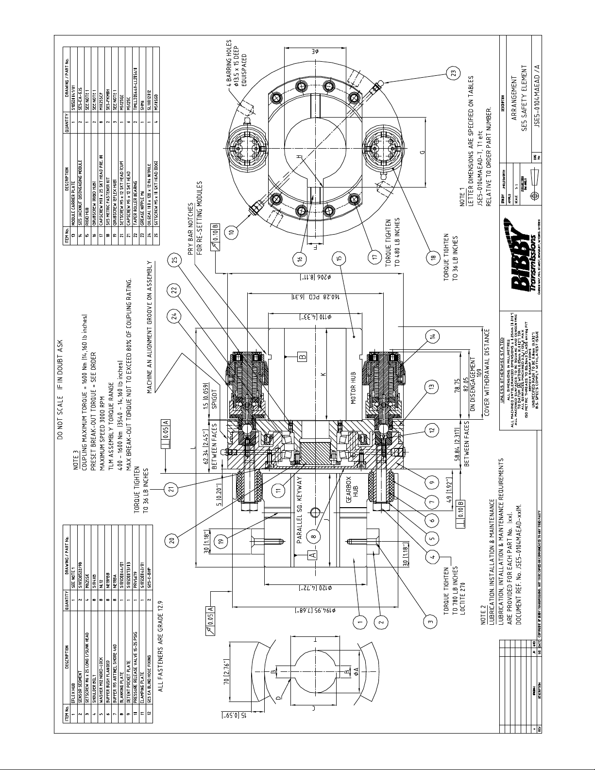
Item Part No. Description Qty.
1 JSE.5-0018-1 Plunger 1
2 JSE.5-0018-2 Outer thrust race 1
3 JSE.5-0018-3 Balls (5 mm) 9
4 JSE.5-0018-4 Inner thrust race 1
5 JSE.5-0018-5 Disc spring 20
6* JSE.5-0018-6 M5 x 25 SHCS 4
7 JSE.5-0018-7 Housing nut 1
8 JSE.5-0018-8 Bushing 1
9 JSE.5-0015-9 Detent ball 12mm 1
10 JSE.5-0015-10 Detent pocket (blind hole) 1
11 JSE.5-0018-11 Housing 1
12
13 JSE.5-0018-13 Grease tting - 6mm 1
14 JSE.5-0018-14 “O” Ring housing 1
15* JSE.5-0018-15 M4 x 15 SHCS 1
16 JSE.5-0018-16 Shim Pack 4
17
18* JSE.5-0018-18 Locking pellet 1
19 JSE.5-0018-19 “O” Ring - bushing 1
20 JSE.5-0018-20 Security screw 2
21 JSE.5-0018-21 Security cover 1
22 JSE.5-0018-22 “O”-Ring (Adjusting Nut) 1
23 JSE.5-0018-23 Jacking nut 1
24 JSE.5-0018-24 End cap 1
25 JSE.5-0018-25 Plunger cap 1
26 JSE.5-0018-26
Setscrew M5 x 10 2LG C Sunk HD
2
* Not shown on this view
6. TORQUE ADJUSTMENT
a. To adjust torque at the job site: Prior to setting Safety Elements
which are new or which have been re-assembled, the desired
release torque for the torque limiter must be known. On
the graph labeled “JSE.5-0104AEA Setting Curve” (Page 3)
read the desired release torque on left. Follow across until
that point meets the setting curve and then follow down to
the required setting for each Safety Element. The numbers
at the bottom of the graph refers to the number of setting
marks on the housing of the Safety Element as measured
from “zero”. Zero varies slightly on each Safety Element
and must be determined independently prior to setting.
b. In order to determine “zero” and set each Safety Element:
1) Remove security screws (2-20) using special
tool and take off Nut Shield. (2-21)
2) Release Set Screw (2-20) using special tool.
3) Turn housing nut (2-7) counter-clockwise using socket
until spring force is removed and the housing nut is free
to turn by hand. Now turn the housing by hand clockwise
and determine the point at which resistance is rst
felt as the springs become engaged. This is the “zero
point”. The number of setting marks required from the
Setting Chart must be counted from this “zero point”.
14 26 25 24 23
1
21
7
5
2
20
22
810 9
19
16
11
4
3
13
4) Using box or open end wrench, turn housing nut until the
required number of setting marks from “zero” are obtained.
5) Turn Set Screw (2-20) until tight. Re-install
Nut Shield using security screws.
6) Repeat steps 1 through 6 for each Safety Element.
7. METHOD OF PRELOADING EACH SAFETY
ELEMENT (BLIND HOLE DETENT)
Safety Elements must be preloaded anytime they are
mounted onto assembly. If mounting the Safety Element (1-
12) prior to preloading follow steps (a) thru (e). If preloading
a mounted Safety Element (1-14), start with step (e).
a. Grease and insert the Detent Pocket (2-10) into the Detent Pocket
Plate (1-9). Fix with SHCS.
b .Grease the bushing (2-8) complete with “O” ring (2-19) and install
over the greased plunger (2-1). Install the greased ball (2-9) in the
hole in the Module Carrier Plate (1-13).
c. Insert the Safety Element assembly (1-14) into the Module Carrier
Plate (1-13) and using feeler gauge, determine shim thickness
required between Housing (2-11) and Module Carrier Plate (1-13).
Figure 2
Section View of
Part # JSE.5-0018
Safety Element
Parts referred to by (Figure # - Part #)
2