BSC 615L User manual

Operating Instructions
Before commissioning the machine, read operating instructions
and observe warning and safety instructions.
PLEASE ALSO READ ORIGINAL
BCS INSTRUCTION MANUAL
Crusader Power Scythes
Manufactured by BCS S.p.A.
Models 615L ●615SL ●630
BCS Crusader Power Scythes
Page 2 CPS/MAX/0817
No liability will be accepted for any damage caused to persons or property
through failure to observe the operating and safety instructions.
!
IMPORTANT READ CAREFULLY
Contents
Page 3 Safety
Page 4 Controls - 615L
Page 5 Controls - 615SL
Page 6 Controls - 630
Page 7 Identication & Stickers
Page 9 Setting Up The Scythe Cutter Bar
Page 11 Types of Transmission & Cutter Bars
Page 12 Identifying Controls
Page 13 Instructions for Use
Page 16 Attaching Scythe to Power Unit
Page 17 Operating Hints
Page 18 Starting the Engine
Operation
Page 19 Stopping the Engine
Page 20 Useful Information
Page 21 Maintenance Guide
Page 23 Risk Assessment
Page 24 Troubleshooting
Page 25 Sound & Vibration Levels
Page 26 Spare Parts
Page 27 Manufacturer Information

BCS Crusader Power Scythes
CPS/MAX/0817 Page 3
Safety
ALWAYS read the original manufacturer’s manual rst
ALWAYS start the engine in the open air
DO NOT smoke when refuelling
DO NOT mix OIL with the fuel
ALWAYS stop the engine before making any adjustments, refuelling, moving or
cleaning, or when the unit is unattended
USE ONLY fuel from containers designed for this purpose - refuel outdoors only and
replace the tank cap securely
IN CASE of petrol spillage move the machine away from the area of spillage and
allow the petrol vapours to dissipate before starting the engine
DO NOT remove any safety guards that are tted
DO NOT touch any moving parts or attempt any maintenance whilst the machine is
running - KEEP HANDS AND FEET AWAY
BEFORE starting work clear the work area of any objects that could damage the
machine
DO NOT allow children or anyone uninstructed to operate the machine - KEEP
ANIMALS AWAY
DO NOT use on slopes or banks of more than 20o
ALWAYS wear suitable clothing to give personal protection including footwear that
offers a good grip
AVOID wearing loose garments that may catch in moving parts
KNOW how to stop the machine in an emergency
NEVER interfere with any control settings on the engine
NEVER select reverse gear with your back to a wall or other immovable object
IF A FAULT develops DO NOT attempt any repair - immediately contact the supplier
from whom the machine was obtained
VISUALLY INSPECT the machine before use - ensure all blades, nuts and bolts are
tight and not worn or damaged and replace blades if necessary
KEEP IN MIND the operator is responsible for accidents or hazards occurring to
people or property

BCS Crusader Power Scythes
Page 4 CPS/MAX/0817
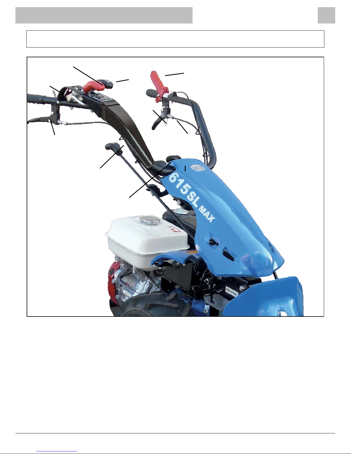
Controls
BCS 615L
Forward / Reverse Lever Engine Stop (OPC) Lever
Throttle Lever
Handlebar Offset
Lever
Wheel Speed
Lever
Handlebar Height
Adjustment Lever
PTO Lever
Clutch Lever
Locking Clip
BCS Crusader Power Scythes
CPS/MAX/0817 Page 5
Controls
Forward / Reverse Lever
Throttle Lever
Handlebar Offset
Lever
Wheel Speed
Lever
Handlebar Height
Adjustment Lever
PTO Lever
Clutch Lever
Locking Clip
Differential
Lever
BCS 615SL
Engine Stop (OPC) Lever

BCS Crusader Power Scythes
Page 6 CPS/MAX/0817
Controls Description
Forward /
Reverse
Lever
Engine Stop (OPC) Lever
Throttle Lever
Handlebar
Offset Lever
Wheel Speed Lever
Handlebar Height
Adjustment Lever
Parking Brake
Lever
Clutch Lever
Locking Clip
BCS 630
Differential Lever
Left Steering
Brake Lever
Right Steering
Brake Lever
PTO Lever

BCS Crusader Power Scythes
CPS/MAX/0817 Page 7
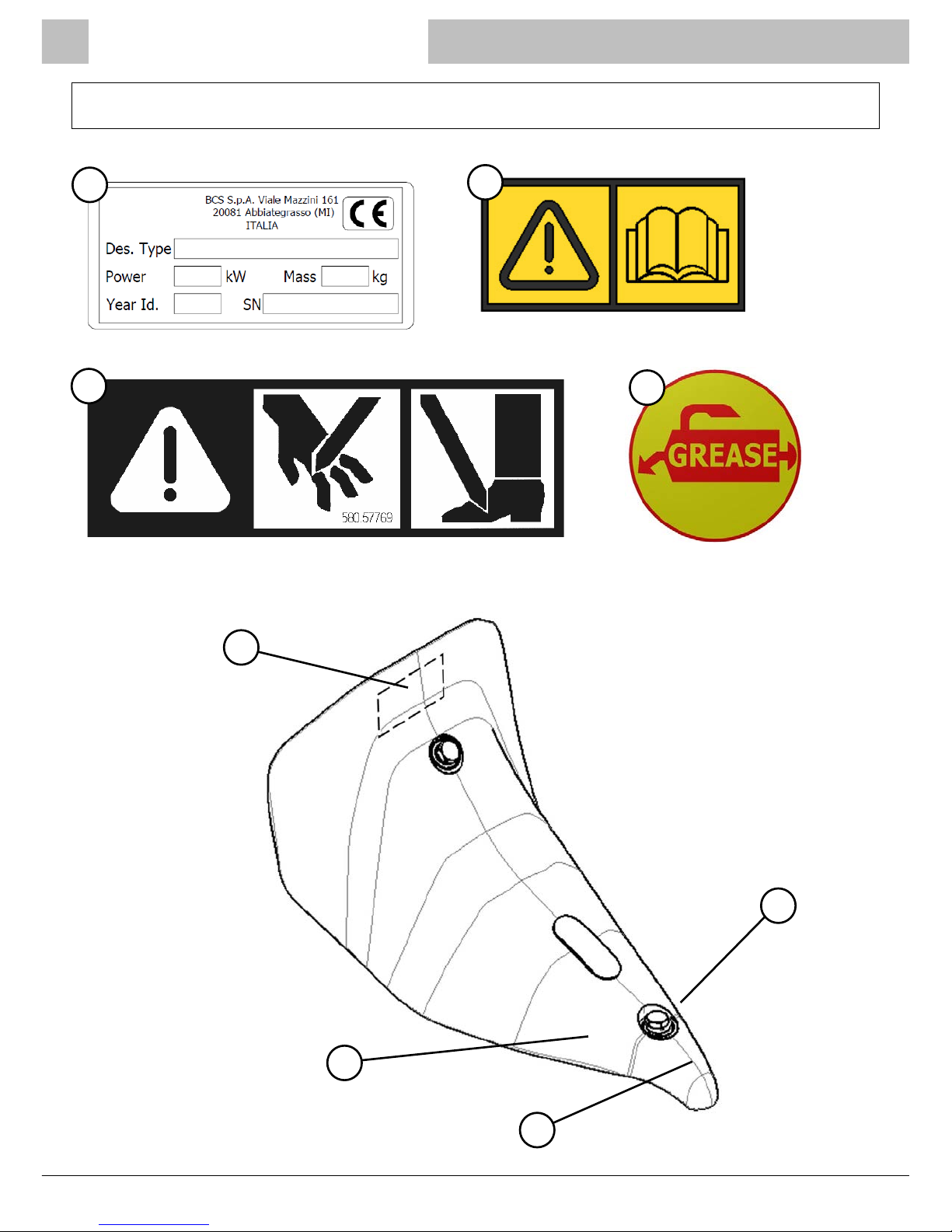
Identication and Stickers
An identication sticker is applied to every machine, as well as product certication in accordance
with the EC Machine Directive (g.2/1).
NOTE: The weight value indicated on the identication plate only refers to the transmission. In
order to obtain the overall weight of the sickle bar, it is necessary to add the weight of the cutter
bar which has been chosen for coupling.
Preservation of the Labels
IMPORTANT! The labels must be kept clean from dust and mud, must always be clearly visible
and legible, and must be replaced if missing or illegible.
If any of the components have to be replaced and they were originally equipped with a safety
label, it is important that the component is returned to its original condition complete with new
labels.
The labels are available as spare parts and can be obtained from your supplier. The part numbers
for each sticker can be found on the parts diagram specic to each machine model, and are
normally also printed on the label.
g.2/1
1 3 2
4 6 7 5
1. Brand
2. Manufacturer
3. Model
4. Minimum Power Required
5. Weight (see note above)
6. Identication Number of
Production Year
7. Serial Number
BCS Crusader Power Scythes
Page 8 CPS/MAX/0817
Identication and Stickers
1
1
2
4
3
2
4
3
58057724
58040548
58057769
BCS Crusader Power Scythes
CPS/MAX/0817 Page 9
Setting Up The Scythe Cutter Bar
What the Machine is Designed For
The scythe cutter bar is designed for mowing grass and
pastures by cutting stems at the base.
This is achieved by coupling the gearbox or transmission
(power unit) to the cutter bar attachment which consists of
the cutting blades.
Opening the Boxes
The scythe attachment is delivered in two boxes, one
containing the transmission and the other containing the
cutter bar.
These should be moved either with a forklift truck or carried
by at least two people. Open the boxes starting from the lid,
and remove the accessories.
Preliminary Checks
Check that the machine is in good condition and has not
been damaged in transit, then proceed with assembly as
indicated in the following points.
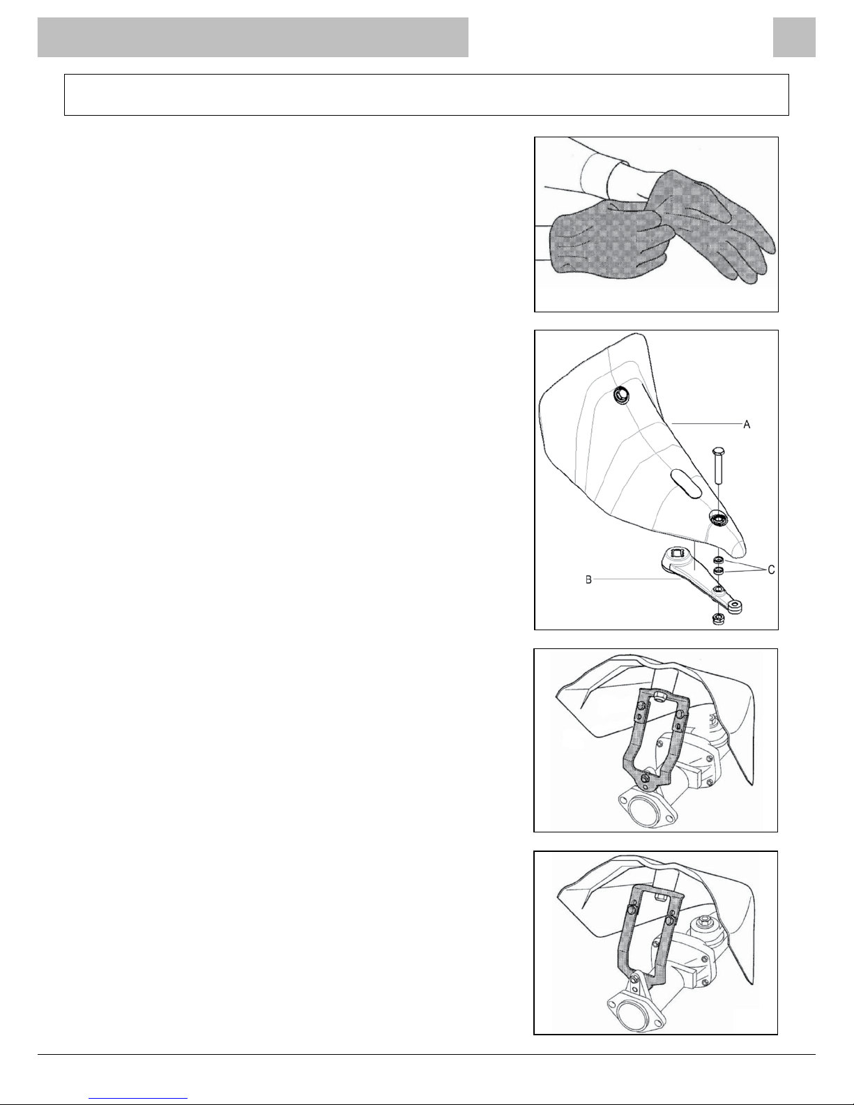
WARNING! Protective gloves must be worn for all assembly
operations, repair and use (g.4/1).
Gearbox Assembly
Fix the protection cover A to crank B as shown in g.4/2.
NB: For dry transmission and short oil bath transmissions two
C spacers must be used, for long oil bath transmissions only
one C spacer is required, and for DUPLEX transmissions no
spacers are required.
Fix the rear side of the protection cover A to the transmission,
as shown in g.4/3 and g.4/4, according to the type of
transmission and gearbox.
g.4/1
g.4/2
g.4/3
g.4/4

BCS Crusader Power Scythes
Page 10 CPS/MAX/0817
Setting Up The Scythe Cutter Bar
Fixing Cutter Bar to Transmission
Lay the cutter bar at and remove the two nuts A and related
washers (g.4/5).
Move the transmission closer to the cutter bar making sure
that the pivot is correctly lodged, then mount the cutter bar
B to control panel A using the two nuts and washers (g.4/6)
and tighten securely.
NB: For the assembly of the DUPLEX bars (with a double
crank mechanism), ensure both pins F and G t into their
housings (g.4/7), then proceed as described above.
IF A HIGH CUT IS NECESSARY: Install the cutting height
adjustment slides (skids) C on the cutter bar using the bolts
provided (g.4/8).
g.4/5
g.4/6
g.4/7
g.4/8
This manual suits for next models
2
Table of contents


