BSi ZGUARD ZG9600 User manual

12/22
BSI, LLC 601 East 64th Avenue, Bldg. A, Denver, Co 80229 800.662.9595 [email protected] bsidesigns.com
Thank you for choosing products from BSI. We appreciate your
business and are available to assist you with all of your needs.
This manual has been designed to help you better understand your
product and its proper usage.
If you have questions that go beyond this detailed manual, please
contact our Customer Service Department at 1.800.662.9595.
Thank you,
The BSI Team
OWNER’S MANUAL & WARRANTY
ZGUARD® FOOD SHIELDS
LIGHTS & WARMERS
Specications subject to change without notice.
OWNER'S MANUAL & WARRANTY

12/22
BSI, LLC 601 East 64th Avenue, Bldg. A, Denver, Co 80229 800.662.9595 [email protected] bsidesigns.com
OWNER'S MANUAL & WARRANTY
NOTES
2

12/22
BSI, LLC 601 East 64th Avenue, Bldg. A, Denver, Co 80229 800.662.9595 [email protected] bsidesigns.com
Contents ..................................................... 3Lights and Warmers
Introduction ................................................ 3Safety Precautions ............................................. 16
Important Owner Information ..................... 3Receiving and Inspecting the Equipment ......... 16
Safety Precautions ..................................... 4Models ............................................................... 16
Receiving and Inspecting the Equipment ..... 4Maintenance and Fixtures ................................. 17
Service and Ordering Parts ............................... 18-19
ZGuard® Food Shields Wiring Installations ............................................. 20-21
Models ....................................................... 4-5 Wiring Diagrams ................................................ 22-23
Basic Components and Layout .................. 6
ZGuard Bracket .......................................... 7
Bracket Mechanism ................................... 8Warranty ............................................................. 24
Glass Management .................................... 8
ZG9600 Assembly ...................................... 9
End Panels ................................................. 10
ZGuard Installation Options ....................... 11-13
ZGuard Accessories - ZSpace .................. 14
The BSI, LLC manual is an important part of your equipment. This document should be stored in a safe
location, as it will be useful for the life of your product. It contains important safety information concerning the
maintenance, operation, and servicing of these products.
Failure to properly use this manual may result in serious injury. Do not operate this equipment unless you
have read and understood the contents of this manual.
Record the model number(s) of your ZGuard and serial number(s), of your warming units to use as a
reference when contacting your local representative or BSI headquarters in Colorado.
BSI, LLC
Business Hours: 8:00 a.m. to 4:30 p.m. MST
Telephone: 800.662.9595
Fax: 303.331.8444
Web Address: www.bsidesigns.com
Model No.:
Serial No.:
Model No.:
Serial No.:
Date of
Purchase:
Other:
3
IMPORTANT OWNER INFORMATION
OWNER'S MANUAL & WARRANTY
TABLE OF CONTENTS

12/22
BSI, LLC 601 East 64th Avenue, Bldg. A, Denver, Co 80229 800.662.9595 [email protected] bsidesigns.com
ZG9500
SAFETY PRECAUTIONS
The ZGuard® food shield must be installed in
accordance with the applicable installation code by a
person familiar with the construction and operation of
the product and the hazards involved.
Even though most equipment is shipped crated, care
should be taken during unloading so the equipment
is not damaged while being moved into your facility.
1. Visually inspect the exterior of the package and
skid or container. Any damage should be noted
and reported to the delivering carrier immediately.
2. If damaged, open and inspect the contents with
the carrier.
3. In the event that the exterior is not damaged, yet,
upon opening, there is concealed damage to the
equipment, notify the carrier. Notication should
be made verbally as well as in written form.
4. Request an inspection by the shipping company
of the damaged equipment. This should be done
within 10 days from receipt of the equipment.
5. Be sure to check that there is no broken glass.
6. Be sure to check that all materials are received.
7. Freight carriers can supply the necessary
damage forms upon request.
8. Retain all crating materials until an inspection has
been made or waived.
9. All ZGuard packages contain drawings for your
installer.
10.All ZGuard packages contain this Owner’s
Manual and Warranty.
4
RECEIVING AND INSPECTING THE EQUIPMENT
ZGUARD MODELS
All ZGuard® models are certied by NSF.
OWNER'S MANUAL & WARRANTY
ZGuard food shields are manufactured in many different
congurations. While the components are all similar, your
model’s glass and posts may not be. Post will either be
aluminum or stainless steel. The models shown below and
on the following page should be maintained in the same
manner based on the instructions within this manual.
If you have questions regarding a ZGuard or are interested
in custom congurations please contact BSI, LLC at
1.800.662.8777.
COMPONENT
ZG9500-2
ZG9500-3 ZG9500-4
ZG9500-5 ZG9500-6
ZG9560 ZG9560-2

12/22
BSI, LLC 601 East 64th Avenue, Bldg. A, Denver, Co 80229 800.662.9595 [email protected] bsidesigns.com
ZG9930-5 ZG9945
ZG9600
ZG9930-2
ZG9945-3
ZG9915 ZG9930
ZG9900
ZG9930-3
ZG9945-4 ZG9945-5
5
ZGUARD® MODELS
ZG9950
OWNER'S MANUAL & WARRANTY
ZG9950-2

12/22
BSI, LLC 601 East 64th Avenue, Bldg. A, Denver, Co 80229 800.662.9595 [email protected] bsidesigns.com
Round Knob
(for angle
adjustment)
End Cap
Heavy-Duty Flange
and Cover
CUSTOMER SIDE
SERVER SIDE
1" Post
Glass Panel
Glass Panel
Left Bracket
(see inset)
Left Bracket Assembly
Right Bracket
Right Bracket Assembly
Fig. 1 shows a two-panel ZG9500 with a center
bracket. Center bracket may be substituted with
a stacked left/right bracket combination for a
different conguration.
Center Bracket
Center Bracket Assembly
BASIC COMPONENTS & LAYOUT
ZGUARD®BRACKETS
SEE EXPLODED VIEW AND PART NUMBERS ON PAGE 7.
Oval Knob
(for height
adjustment)
6
Fig. 2 shows section view of Fig. 1.
OWNER'S MANUAL & WARRANTY

12/22
BSI, LLC 601 East 64th Avenue, Bldg. A, Denver, Co 80229 800.662.9595 [email protected] bsidesigns.com
7
In the event your ZGuard product needs service and requires major repairs, contact your local
installer for assistance.
If you have questions about the products or need to replace minor parts, contact BSI, LLC
at 800.662.9595.
Full Assembly Clamp Section Only
Bracket Assembly - Exploded View
A
B
C
D
E
F
Location Part # Part Name
A553 Left Bracket Assembly
B 554 Center Bracket Assembly
C 555 Right Bracket Assembly
D322 Left Post Clamp
E424 Center Post Clamp
F323 Right Post Clamp
G 324 Post Clamp Insert
H321 Glass Mounting Clamp
I 326 Round Knob
J 336 Decorative Nut
K457 Oval Knob
L484 Clear Mylar Spacer
M1/4-20 x 1-1/4" Machine Screw Flat
Phillips
N553RX Left Bracket Right Half Arm Assy.
O554X Center Bracket Half Arm Assembly
P 555LX Right Bracket Left Half Arm Assy.
J
K
M
L
G
H
I
ZGUARD® BRACKET ASSEMBLY AND PARTS
* When ordering you MUST designate nish/color.
OWNER'S MANUAL & WARRANTY
Half Arm Assembly
N O
P

12/22
BSI, LLC 601 East 64th Avenue, Bldg. A, Denver, Co 80229 800.662.9595 [email protected] bsidesigns.com
8
OWNER'S MANUAL & WARRANTY
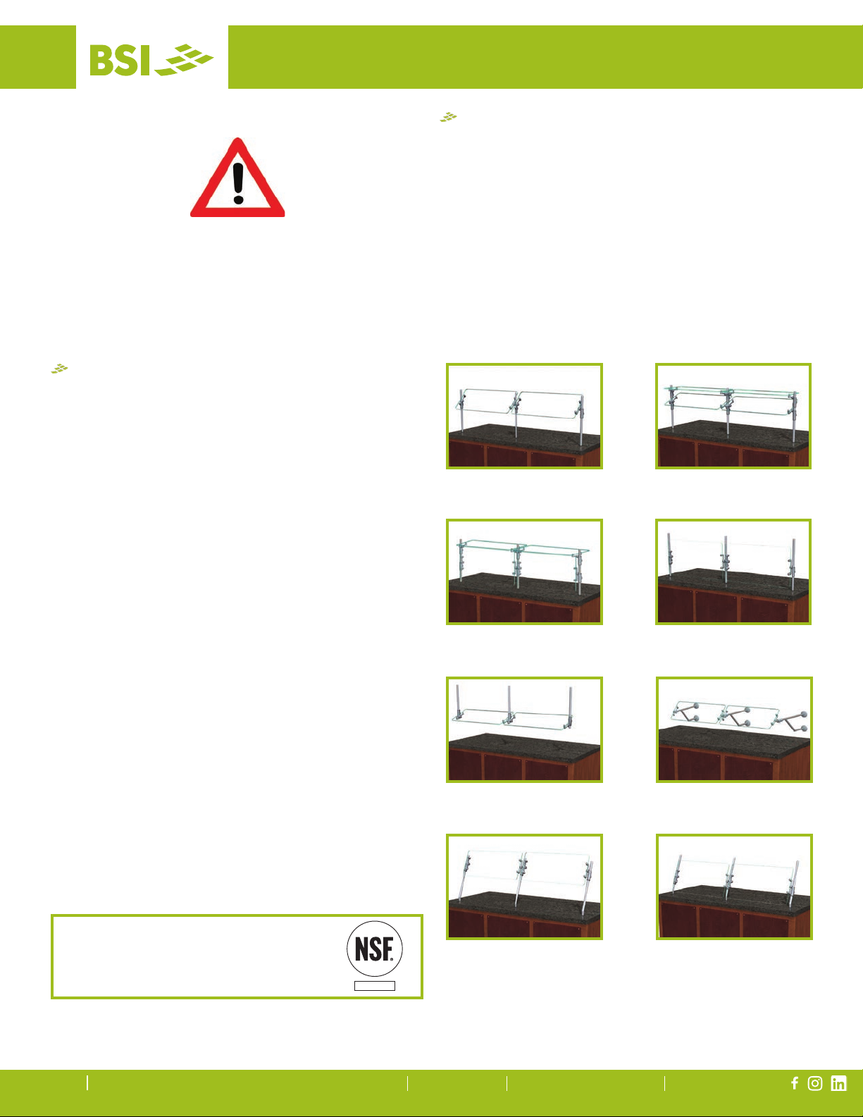
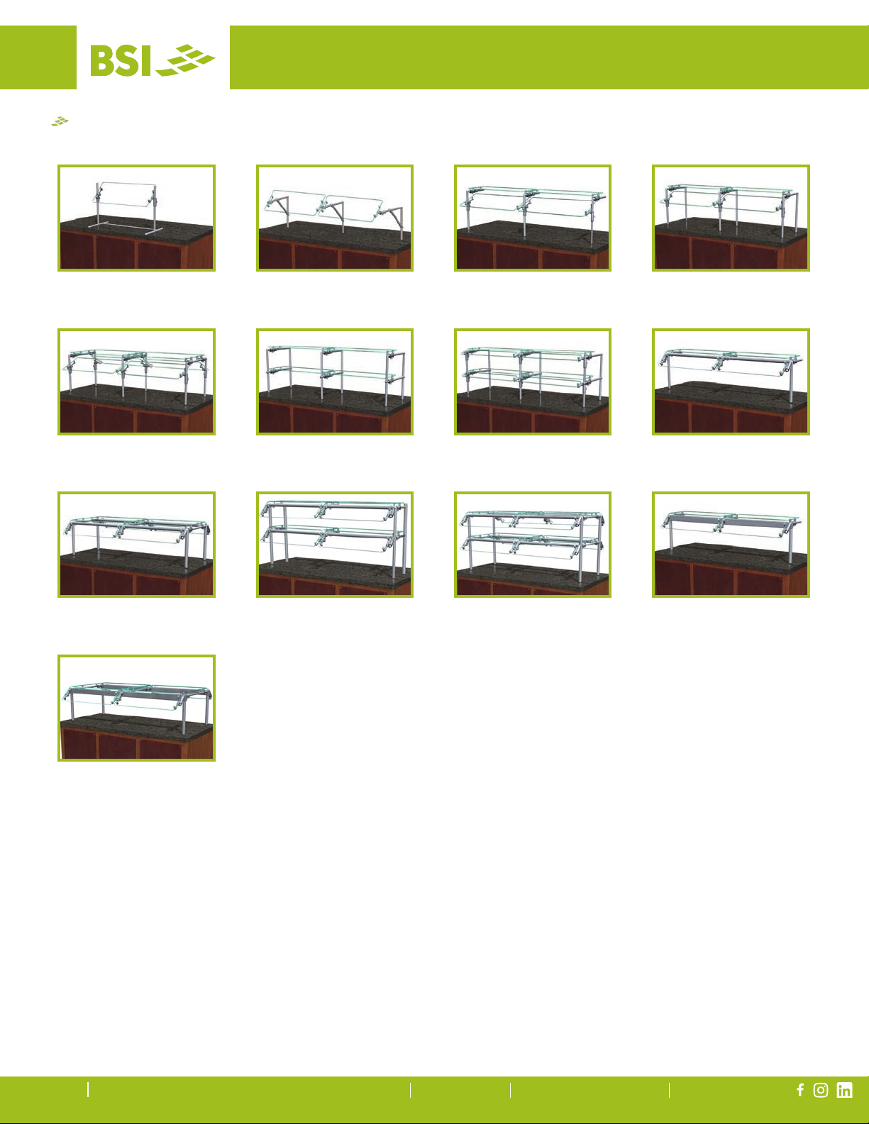
Glass panels can be tilted forward or backwards in 22 .5o increments. The panels (glass and bracket
combination) can be raised or lowered by adjusting the brackets. As detailed in Figure #1 (page 6), the
bracket’s Oval Knob is shown on the Server Side. Oval Knob location varies based on food shield conguration.
The bracket’s Round Knob, which holds the Glass Mounting Clamp in place, always faces the food.
Cleaning your new ZGuard product is key to its long life.
BSI recommends the following for keeping your
product clean:
• Wipe the surface with a clean, damp cloth to
remove ngerprints, dust, etc.
• Spray with a light coating of glass cleaner to
remove grease or other dirt. Use a non-ammonia
cleaner.
• Do not polish ZGuard with any brass polish. Your
ZGuard has a durable nish and will maintain
its nish for years if well maintained. (Polishing
the nish with a polishing agent of any kind will
destroy the coating.)
• Do not scrub the surface with any abrasive
substance such as steel wool, pot scrubbers,
abrasive powders, or similar products, as it will
remove the protective coating.
• If unit is tted with a BSI Stealth warmer, do not
clean the glass or housing when warmer is hot.
Cleaning warmer when hot can cause staining or
damage to warmer nish.
ZGuard food shield systems that are equipped
with a shelf are not intended to withstand
heavy weights. Do not exceed 75lbs. total
weight of all display items across a 36" panel
of 3/8" thick glass.
Food Shield: ZG9500
(glass panel positioned at 90o to post)
Posts & Brackets: Brushed Aluminum
Glass: 36" x 14” (3/8" thick)
Mounting: Above Counter
Time: 24 hours
GLASS AND BRACKET POSITION
CLEANING INSTRUCTIONS
GLASS LIMITATIONS TESTING PARAMETERS
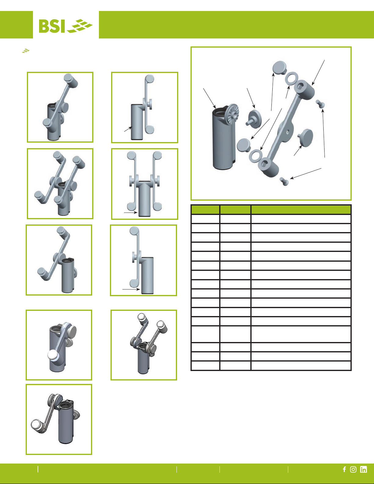
ZGUARD® BRACKET ADJUSTMENT
ZGuard brackets allow you
to adjust the food shield
height and angle of glass.
Referred to as the 'home'
position, bracket and
glass will be in vertical
position.
With the assistance from
a second person, take the
following steps to adjust
your ZGuard.
1. To raise or lower the bracket, loosen the Oval
Knob from the Post Clamp. Slide to new position
and tighten. (See Illustration #1)
2. To adjust angle of the glass, loosen the Round
Knob and then adjust the glass angle to desired
location. (See Illustration #1)
Illustration #1: Bracket and
glass in 'Home' position.
Oval
Knob
Round
Knob

12/22
BSI, LLC 601 East 64th Avenue, Bldg. A, Denver, Co 80229 800.662.9595 [email protected] bsidesigns.com
ZGUARD® ZG9600 ASSEMBLY
Alternate Crossbar
Location
Alternate Post
Location
ZG9600 Assembly Instructions
1. From the underside, use the provided
screws to attach the stabilizer to each
foot. There are two alternate locations for
stabilizer placement.
2. Right side up, screw in the two posts.
There are two alternate locations for post
placement.
3. In the non-used post holes screw in the
provided foot plugs.
4. Afx the glass panel to the left and right
bracket assemblies.
5. Slide the brackets onto the left and right
post. Tighten bracket at level height for
secure hold.
6. With the brackets parallel to counter,
screw glass panel to the brackets.
7. Adjust glass angle and height as needed.
Location Part # Part Name
1Market Stabilizer Screw
2 415 Market Stabilizer
3 416 Market-Style Foot
4 348 Post
5 361 Foot Plug
6Glass Panel
7 553 Left Bracket Assembly
8 555 Right Bracket Assembly
3
2
4
1
7
6
8
5
9
OWNER'S MANUAL & WARRANTY

12/22
BSI, LLC 601 East 64th Avenue, Bldg. A, Denver, Co 80229 800.662.9595 [email protected] bsidesigns.com
OWNER'S MANUAL & WARRANTY
NSF REQUIRED END PANELS FOR ZGUARD®
To meet NSF guidelines, end panels are included on all BSI
quotations unless otherwise specied.
Location Part # Part Name
9 336 Decorative Nut
10 484 Clear Mylar Spacer
11 15756 End Panel Bracket Assembly
12
1/4-20 x 1-1/4" Machine Screw Flat Phillips
10
9
10
12
11
NSF End Panel Requirement Exemption
NSF/ANSI Standard 2 - 2018
5.36.1.6.2 A food shield intended to be installed a maximum of 3 inches (76 mm) from a building
wall perpendicular to the food shield is exempt from the requirements of 5.36.1.6.1 provided
that the height of the building wall is not lower than the overall height of the food shield. The
manufacturer's specication sheet, brochure, installation instructions, and/or shop drawings shall
include these building wall and proximity requirements.

12/22
BSI, LLC 601 East 64th Avenue, Bldg. A, Denver, Co 80229 800.662.9595 [email protected] bsidesigns.com
ABOVE-COUNTER INSTALLATION FOR 1" ZGUARD® POSTS
For Stainless Steel Counter
SS1: EZ Mount 2" x 8" Flange
For Millwork Counter
MW1: Heavy-Duty Flange
For Millwork Counter
MW2: Narrow Flange
24
27
26
28
25
19
20
21
23
22
18
25
2"
8-1/8"
1"
Above Counter: EZ Mount Flange
Stainless Steel Counter
Steel Backing Plate with Tem-
plate for Holes, S/S Screws,
and Rivets Provided.
Heavy-Duty Flange
9/16"
2"
3-1/2"
Narrow Flange
3"
2"
1-1/4" 1/2"
18
18
Location Part # Part Name
18 348 1" Threaded Post
19 485 EZ Mount Center Flange Cover
20 10-32 x 1” S/S Screw Flat Phillips
21 470 EZ Mount Base Flange Centered
22 Rivet Nut
23 473 EZ Mount Flange Plate Centered
24 464 Heavy-Duty Flange Cover
25 #12 x 2" A Tapping Screw Flat Phillips
26 471 Heavy-Duty Flange
27 465 Narrow Flange Cover
28 378 Narrow Flange
29 442 Grommet
11
OWNER'S MANUAL & WARRANTY

12/22
BSI, LLC 601 East 64th Avenue, Bldg. A, Denver, Co 80229 800.662.9595 [email protected] bsidesigns.com
12
For below-counter installation a 1-1/4"
diameter grommet is required. (Part #442)
UNDER-COUNTER INSTALLATION FOR 1" ZGUARD® POSTS
Refer to page 11 for part numbers.
For Stainless Steel Counter
(requires under-counter reinforcement and access)
SSU3: Heavy-Duty Flange (-H) or Narrow Flange (-N)
For Stainless Steel Counter
(requires under-counter reinforcement and access)
SSU5: Heavy Duty Flange (-H) or Narrow Flange (-N)
For Millwork Counter
MWU3: Narrow Flange
For Millwork Counter
MWU5: Heavy Duty Flange
For Millwork Counter
MWU4: Compression Installation
(not recommended for solid surfaces)
29
SSU3-H Shown SSU5-H Shown
29
Verify
Verify
26
Plate by OthersAngle by Others
Plate by Others
Verify Counter Thickness or Under-Counter Installation Depth in Inches
OWNER'S MANUAL & WARRANTY
3-1/2"
29
Hex Nut
2" Solid
Threaded
Ring
1-5/8" Min.
3-1/2" Diameter
Washer
29
3"
26

12/22
BSI, LLC 601 East 64th Avenue, Bldg. A, Denver, Co 80229 800.662.9595 [email protected] bsidesigns.com
ABOVE-COUNTER INSTALLATION FOR 1-1/2" ZGUARD® POSTS
Refer to page 11 for part numbers.
For Millwork Counter
Surface Installation 720A/726A:
Steel Post and Flange w/Flange Cover
For Millwork Counter
Surface Installation 725A:
Cut Flange
726A Flange
Cover Cut Flange
720A Steel Post
& Flange
For Millwork Counter
Concealed Fastener
(not for cantilever units)
UNDER-COUNTER INSTALLATION FOR 1-1/2" ZGUARD POSTS
Under-Counter Installation 720A/726A:
Steel Post and Flange w/Flange Cover
Under-Counter Installation 725A:
Narrow Custom Flange
Under-Counter Installation 720A:
Steel Post and Flange w/out Flange Cover
(requires under-counter reinforcement and access)
720A Steel Post
& Flange
726A Flange
Cover
Grommet (29)
Concealed
Fastener
720A Steel Post
& Flange
Grommet (29)
720A Steel Post
& Flange
Plate by Others
Angle by Others
Verify
FLANGE AND FLANGE COVER DIMENSIONS
725A Cut Flange 726A Flange Cover720A Flange
4"
2-3/8"
3-7/8" 4"
5/8"
13/16"
13
OWNER'S MANUAL & WARRANTY

12/22
BSI, LLC 601 East 64th Avenue, Bldg. A, Denver, Co 80229 800.662.9595 sales@bsidesigns.com bsidesigns.com
Specifications subject to change without notice.
OWNER'S MANUAL & WARRANTY
OWNER’S MANUAL & WARRANTY
LIGHTS & WARMERS
BSI, LLC w601 E 64th Avenue, Bldg. A wDenver, CO 80229 wPhone: 1.800.662.9595 wFax: 303.331.8444 wWeb: www.BSIdesigns.com

12/22
BSI, LLC 601 East 64th Avenue, Bldg. A, Denver, Co 80229 800.662.9595 sales@bsidesigns.com bsidesigns.com
LIGHTS & WARMERS
Even though most equipment is shipped crated, care
should be taken during unloading so the equipment
is not damaged while being moved into your facility.
1. Visually inspect the exterior of the package and
skid or container. Any damage should be noted
and reported to the delivering carrier immediately.
2. If damaged, open and inspect the contents with
the carrier.
3. In the event that the exterior is not damaged, yet,
upon opening, there is concealed damage to the
equipment, notify the carrier. Notification should
be made verbally as well as in written form.
4. Request an inspection by the shipping company
of the damaged equipment. This should be done
within 10 days from receipt of the equipment.
5. Be sure to check that there is no broken glass.
6. Be sure to check that all materials are received.
7. Freight carriers can supply the necessary
damage forms upon request.
8. Retain all crating materials until an inspection has
been made or waived.
9. All packages contain drawings for your installer.
10. All Light and Warmer packages contain this
Owner’s Manual and Warranty.
ALL LIGHTS,WARMERS AND COMBO UNITS
ARE SHIPPED USING ZIP TIES TO SECURE
UNITS DURING TRANSIT.AFTER INSTALLATION,
CAREFULLY REMOVE ALL ZIP TIES.
Food shield systems can be built with lights, warmers
or a combination of the two. Proper maintenance
for these products is very important for safety. The
following pages will detail the proper methods of
keeping your product clean, how and where to
exchange parts, and include diagrams for proper
wiring.
This product must be installed in
accordance with the applicable
installation code by a person familiar
with the construction and operation of
the product and the hazards involved.
Slimline Light Model 2580
Stealth Warmer Model 790
Stealth Warmer & Light
Combo Model 705
Stealth Double Warmer &
Light Combo Model 500
RECEIVING AND INSPECTING THE EQUIPMENT
MODELS
All Light and Warmer models are
certied by NSF.
Specifications subject to change without notice.
OWNER'S MANUAL & WARRANTY
BSI, LLC w601 E 64th Avenue, Bldg. A wDenver, CO 80229 wPhone: 1.800.662.9595 wFax: 303.331.8444 wWeb: www.BSIdesigns.com

12/22
BSI, LLC 601 East 64th Avenue, Bldg. A, Denver, Co 80229 800.662.9595 sales@bsidesigns.com bsidesigns.com
Once your Food Shield has been properly installed
and you have removed all zip ties from transporta-
tion, it will be important to keep your light, warmer or
combo unit clean to prolong the life of the product.
BSI recommends the following for keeping your
product clean:
• Be sure to turn the power on your light or warmer
off before cleaning. Only clean when stealth
warmer is cool. Cleaning when the warmer is
hot can cause staining or damage to food
warmer nish.
• Wipe the surface with a clean, damp cloth to
remove fingerprints, dust, etc.
• Spray with a light coating of glass cleaner to
remove grease or other dirt. Use a non-ammonia
cleaner.
• Be sure not to spray any cleaning product directly
into the bulbs, fixtures or heating elements.
When a fluorescent bulb burns out and needs to be
replaced you will need to do the following:
• Turn off power to all lights and warmers.
• Carefully push the white lever to the opposite
side, rotating the bulb 90o.
• Rotating the lever will unlock the bulb. The pins
will now be visible through the open slots at each
end. Caution: At this position, bulbs are free to fall
down through open slots.
• If the bulb does not easily slide out from the
holders, tap lightly on housing first, then carefully
use needle-nose pliers to grab the bulb, evenly
pulling it down and out.
• Once the defective bulb is removed, remove the
white lever end cap from the bulb prongs and
proceed to place it on the new bulb prongs.
• With the new bulb in hand, evenly push the pins
on both ends up and into the open slots of the
lamp holders.
• Carefully push the white lever to the opposite
side, rotating the bulb 90oand locking it into
place. Pins will no longer be visible.
Bulb Installation Lever
Do not use high-output bulbs.
Use coated, shatter-proof bulbs.
Each BSI light, warmer or combo unit contains
an Identification Sticker. This sticker provides the
customer with the following information:
• Serial Number
• Model Number
• Manufacture Date
• Electrical Information
Sample Stealth Warmer Sticker with everything you
need to know about your unit.
IDENTIFYING YOUR PRODUCT
CLEANING INSTRUCTIONS
Specifications subject to change without notice.
OWNER'S MANUAL & WARRANTY
CHANGING THE FLUORESCENT BULB
BSI, LLC w601 E 64th Avenue, Bldg. A wDenver, CO 80229 wPhone: 1.800.662.9595 wFax: 303.331.8444 wWeb: www.BSIdesigns.com

12/22
BSI, LLC 601 East 64th Avenue, Bldg. A, Denver, Co 80229 800.662.9595 sales@bsidesigns.com bsidesigns.com
Specifications subject to change without notice.
OWNER'S MANUAL & WARRANTY
When a LED bulb burns out and needs to be
replaced you will need to do the following:
• Turn off power to all lights and warmers.
• Carefully unscrew the end plate and slide out the
entire LED light.
• If mutiple lights are connected to each other
carefully disconnect Serial Connector or Power
Connector.
• Once dead light is removed, replace with new LED
light. Carefully reconnect the connector and slide in
the light bar.
• Replace end cover and the two screws.
CHANGING THE LED BULB
End Plate
In the event that your Lights or Warmers need service
and require major repairs, contact your local installer
for assistance.
If you have questions about the products or need
to replace minor parts you may contact BSI, LLC at
1.800.662.9595.
Part # Description (All bulbs 4100K)
508-8-C F8-T5/CW - 12" Long
508-14-C F14-T5/CW - 22" Long
508-21-C F21-T5/CW - 34" Long
508-28-C F28-T5/CW - 46" Long
508-35-C F35-T5/CW - 58" Long
512 Bulb Installation Lever
Bulb
Bulb
Installation Lever
PARTS & SERVICE
ORDERING NEW FLUORESCENT BULBS
ORDERING NEW LED LIGHTS
Part # Description
16289 Kelly LED:_12"_LED_Light_Bar
16290 Kelly LED:_18"_LED_Light_Bar
16292 Kelly LED:_36"_LED_Light_Bar
16505 Kelly LED:_48"_LED_Light_Bar
16293 Kelly LED:_10'_Power_Cord_w/o_Plug
16294 Kelly LED:_Serial_Connector
16295 Kelly LED:_6" Power_Connector
BSI, LLC w601 E 64th Avenue, Bldg. A wDenver, CO 80229 wPhone: 1.800.662.9595 wFax: 303.331.8444 wWeb: www.BSIdesigns.com

12/22
BSI, LLC 601 East 64th Avenue, Bldg. A, Denver, Co 80229 800.662.9595 sales@bsidesigns.com bsidesigns.com
Part # Description
492-18-BK Element:_18"_120V_Heater_350W
492-24-BK Element:_24"_120V_Heater_500W
492-30-BK Element:_30"_120V_Heater_660W
492-36-BK Element:_36"_120V_Heater_800W
492-42-BK Element:_42"_120V_Heater_950W
492-48-BK Element:_48"_120V_Heater_1100W
492-54-BK Element:_54"_120V_Heater_1250W
492-60-BK Element:_60"_120V_Heater_1400W
492-66-BK Element:_66"_120V_Heater_1560W
Part # Description
496-24-BK Element:_24"_208V_Heater_500W
496-30-BK Element:_30"_208V_Heater_660W
496-36-BK Element:_36"_208V_Heater_800W
496-42-BK Element:_42"_208V_Heater_950W
496-48-BK Element:_48"_208V_Heater_1100W
496-54-BK Element:_54"_208V_Heater_1250W
496-60-BK Element:_60"_208V_Heater_1400W
496-66-BK Element:_66"_208V_Heater_1560W
240V Heat Elements are a Special Order Item.
Contact BSI at 1.800.662.9595 to place an order.
Heat Warning
Sticker Here
Heating Element
Element
Clips
Wire Clip
Wire Clip
Electrical Shock
Warning Sticker Here
On all three Stealth Warmer units the tubular heating
element can burn out, similar to a light bulb.
Replacing the tubular heating element should be
completed by a Professional Service Technician. If
you have additional questions please contact
BSI at 1.800.662.9595.
REPLACING THE TUBULAR HEATING ELEMENTS
ORDERING NEW HEATING ELEMENTS
Specifications subject to change without notice.
OWNER'S MANUAL & WARRANTY
BSI, LLC w601 E 64th Avenue, Bldg. A wDenver, CO 80229 wPhone: 1.800.662.9595 wFax: 303.331.8444 wWeb: www.BSIdesigns.com

12/22
BSI, LLC 601 East 64th Avenue, Bldg. A, Denver, Co 80229 800.662.9595 sales@bsidesigns.com bsidesigns.com
Specifications subject to change without notice.
OWNER'S MANUAL & WARRANTY
WIRING INSTALLATIONS
Fluorescent Light/StealthTM Warmer Combo
• All wiring should be performed by a certified technician.
• Wires are routed through wire chase/support legs per approved shop drawings.
• Mount the ballast box, infinite controllers near the wire chase/support leg.
• The ballast box, infinite controllers, light switch and 6 feet of conduit/wiring exiting support legs are all provided with all
models of BSI, LLC Food Shields. All other components are provided by others.
StealthTM Warmer Combo
Heat Light Heat (Fluorescent)
Typical Food Shield Light and Warmer Installations
Light/Warmer
Combo
Food
Shield
Ballast Box
(14" x 3" x 2")
Counter Light Switch
Mounted
in a Box
Junction
Box
Supply Power
(by electrical contractor)
Infinite
Controller
Mounted
in a Box
Warmer/Light/Warmer
Combo
Food
Shield
Ballast Box
(14" x 3" x 2")
Counter
Light Switch
Mounted
in a Box
Junction
Box
Supply Power
(by electrical contractor)
Two Infinite
Controller
Mounted
in a Box
Light/Warmer
Combo
Food
Shield
Counter
Light Switch
Mounted
in a Box
Junction
Box
Supply Power
(by electrical contractor)
Infinite
Controller
Mounted
in a Box
LED Light/StealthTM Warmer Combo
StealthTM Warmer Combo
Heat Light Heat (LED)
Warmer/
Light/
Warmer
Combo
Food
Shield
Counter
Light Switch
Mounted
in a Box
Junction
Box
Supply Power
(by electrical contractor)
Two Infinite
Controller
Mounted
in a Box
LED Light is direct
connection to junction box.
LED Light is direct
connection to junction box.
BSI, LLC w601 E 64th Avenue, Bldg. A wDenver, CO 80229 wPhone: 1.800.662.9595 wFax: 303.331.8444 wWeb: www.BSIdesigns.com

12/22
BSI, LLC 601 East 64th Avenue, Bldg. A, Denver, Co 80229 800.662.9595 sales@bsidesigns.com bsidesigns.com
Specifications subject to change without notice.
OWNER'S MANUAL & WARRANTY
WIRING INSTALLATIONS
Fluorescent Lights
• All wiring should be performed by a certified technician.
• Wires are routed through wire chase/support legs per approved shop drawings.
• Mount the ballast box, infinite controllers near the wire chase/support leg.
• The ballast box, infinite controllers, light switch and 6 feet of conduit/wiring exiting support legs are all provided with all
models of BSI, LLC Food Shields. All other components are provided by others.
StealthTM Warmer
Typical Food Shield Light and Warmer Installations
Fluorescent
Light
Food
Shield
Ballast Box
(14" x 3" x 2")
Counter
Light Switch
Mounted in a Box
Junction
Box
Supply Power
(by electrical contractor)
Warmer
Food Shield
Infinite Cotroller
Mounted in a Box
Counter
Junction Box
Supply Power (by electrical contractor)
LED Lights
LED Light
Food
Shield
Counter
Light Switch
Mounted in a Box
Junction
Box
Supply Power
(by electrical contractor)
LED Light is direct
connection to junction box.
BSI, LLC w601 E 64th Avenue, Bldg. A wDenver, CO 80229 wPhone: 1.800.662.9595 wFax: 303.331.8444 wWeb: www.BSIdesigns.com
This manual suits for next models
18
Table of contents
Popular Commercial Food Equipment manuals by other brands

ACP
ACP MRX2SW Service manual

Diamond
Diamond ES6/BMT-N manual

Henny Penny
Henny Penny McDonald's LOV MVE 07X Electric Series quick start guide

Atwood
Atwood SCALE-O-MATIC S302 Operation and safety manual

Everidge
Everidge Preprite PVS50 Manual for use and maintenance

Vollrath
Vollrath STOELTING E122 Service manual