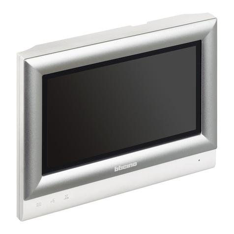
Bticino H4687 User manual

H4687
Video Touch Screen
Installation manual
12/10-01 PC

2

Installation manual
3
Contents
Video Touch Screen
1 Introduction 4
1.1 Contents of the package 4
1.2 Environmental considerations 4
2 Description Of The Video Touch Screen 5
2.1 Dimensions 5
2.2 Installation rules 5
2.3 Mounting 6
2.4 Layout of the connectors 7
2.5 Description of the connections 7
2.6 System specifications 9
3 Operating system 10
3.1 Changing the language 10
3.2 Operating System Version 10
3.3 Alphanumeric keyboard on the screen 10
3.4 Running the programs automatically 11
3.5 Local area network connection (LAN) 11
3.6 Protection of the c:\ drive with Enhanced Write Filter (EWF) 11
4 Touch Screen 12
4.1 Technology of the resistive touch screen 12
4.2 Touch screen calibration 12
5 Factory settings 13
6 Operating system recovery using the USB key 14

4
1 Introduction
1.1 Contents of the package
Check the package contents, which must be made up of:
• Video Touch Screen H4687
• Black 3-way power supply connector for power supply
• 4 long fastening screws
• Aluminum painted front frame
• Instructions for installation
• CD-ROM containing MHVISUAL software and PDF-format manuals
• Operating system recovery USB key
1.2 Environmental considerations
The following guidelines are intended to ensure that the Video Touch Screen works safely and reli-
ably throughout its lifetime.
• Install the product on brick walls. Installing the product on cement or plasterboard walls is not
recommended as they do not guarantee good dissipation of the heat generated by the device.
• Do not install the product on walls exposed to the south or which are subject to unnatural heating.
• Do not install the product near radiators or other heating components.
• Make sure that the room’s humidity does not exceed the limits specified. In very dry rooms electrostatic
charges are generated which could damage the device.
Do not install the product on walls of potentially inflammable materials such as wood or
plastic supports.
Always connect the Video Touch Screen to the earth to avoid electric discharges that may
cause damage.

Video Touch Screen
5
Installation manual
2.1 Dimensions
2 Description Of The Video Touch Screen
2.2 Installation rules
The product has been designed for wall installation in a Bticino box of the Multibox F215/24S
series.
The Video Touch Screen has an integrated power supply. It must therefore be powered directly at
230 Vac.
• Only use the recommended installation boxes which must be fitted in the wall at a height from
the floor of at least 1.5 metres and flush mounted in the wall so that its outside edge is recessed
at least 5 millimetres in the wall. This is to avoid the external surround plate not being perfectly
in contact with the wall surface.
• Provide a cable trough for the power supply separate from that used to carry the signal cables
such as the Ethernet cable, USB cable and telephone cable.
• Provide an external 220 V ON/OFF switch so that the power supply can be switched OFF before
working on the computer for maintenance (close Windows before disconnecting the power
supply).
• Since the apparatus does not have an internal protection against overcurrents or short-circuits,
an appropriate external protection device is required.
370 mm 65 mm 26 mm
312,5 mm
204,5 mm
294 mm

6
2.3 Mounting
green
connector
earthing
point
• Connect the earth wire both to the power
supply socket and to the earthing point on
the Video Touch Screen casing.
• Connect the power supply wires to the green
connector (supplied).
• Connect the power supply connector, the Eth-
ernet connector, the USB connector, and the
serial connector that may be present to the
Video Touch Screen.
• Insert the Video Touch Screen into the hole
in the wall and fasten it with the four long
screws.
• Install the front surround plate making sure
that the rounded pins are aligned to the holes
containing the seal springs.
2 Description Of The Video Touch Screen

Video Touch Screen
7
Installation manual
2.4 Layout of the connectors
Ethernet connector
Use this connector to connect the Video Touch Screen to an Ethernet 10/100 Mbps - 1 Gbps net-
work.
The green LED lights up to indicate that the Ethernet network is connected.
2.5 Description of the connections
The signals of the individual connectors are described in the following section.
Power connector
Connect the 220 V power supply wires and the earth wire to the black connector supplied.
Always disable the computer’s 220 V power supply before performing any maintenance.
Power
Speaker Jack
EthernetCOM ports
USB
USB
Headset jack

8
To connect the Video Touch Screen to an Ethernet HUB, use a straight pin-to-pin shielded cable.
To connect the Video Touch Screen to another external PC use a cross-over cable as in the follow-
ing diagram:
PIN 1
PIN 1
PIN
1
2
3
4
5
6
7
8
PIN
3
6
1
4
5
2
7
8
Wire 1
Wire 2
Wire 3
Wire 4
Wire 5
Wire 6
Wire 7
Wire 8
J1 J2
J1 J2
PIN 8
PIN 8
USB connector
Use these connectors to connect external devices to the Video Touch Screen, such as mouse, key-
boards, mass memory, e.g. a flash memory, or CD-Roms.
Use a shielded USB cable.
If the Ethernet connection cable is subject to induced or irradiated radiations, the perform-
ance of the Ethernet connection may deteriorate. Correct channelling of the Ethernet
cables and the power supply cables guarantees optimum device working. The installer is
responsible for taking all precautions to ensure that the connections are made as well as
possible.
2 Description Of The Video Touch Screen

Video Touch Screen
9
Installation manual
CPU Intel Atom N270 1.6 GHz
RAM 2 Gb DDR2
Mass memory CF 16 Gb
Serial 2x - COM1: RS232; COM2: RS232
USB 3x USB 2.0
LAN 1x RJ45 Gigabit Ethernet
Speaker 2x - internal
Microphone 2x - internal
Audio 1x MIC-IN phone jack; 1x SPK-OUT phone jack
Video output 1x DB15 VGA, resolution 1600x1200 @ 85 Hz/2048x1536 @ 75 Hz
Display 1x TFT 15" LVDS integrated, resolution 1024x768
Touch Screen 1x resistive 15” internal USB interface
Keyboard and mouse USB connection
Operating system Windows Embedded Standard 2009 MultiLanguage SP3
Power supply 1x 50 W; 90 – 260 Vac
Typical absorbed current 250 mA @ 220 Vac (in “as is” HW conguration)
Maximum current absorbed 700 mA @ 220 Vac (in “as is” HW conguration)
Room temperature range 0 – 30 °C
Operative humidity range 20 – 85 % without condensation
Front cover Extruded aluminium
Assembly BTicino Multibox F215/24S ush mounted box and drawings
2.6 System specifications
abel electric features

10
3 Operating system
The operating system of the Video Touch Screen H4687, is Windows Embedded Standard 2009
MultiLanguage SP3, which has different features when compared with traditional Windows sys-
tems. The installed operating system supports the following languages:
• Arabic
• Chinese (simplified)
• Chinese (traditional)
• Czech
• Danish
• Dutch
• English
• Finnish
• French
• German
• Greek
• Hebrew
• Hungarian
• Italian
• Japanese
• Korean
• Norwegian
• Polish
• Portuguese
• Russian
• Spanish
• Swedish
• Turkish
The size of the operating system is 2.8 Gb approximately. The operating system is found in the C:\
partition. There is also a D:\ partition of approximately 6 Gb.
The C:\ partition can be protected from unwanted changes with the EWF (ENHANCED WRITE FIL-
TER) function, using the EWF manager.
The use of this tool is only permitted to users with administrator rights, see the relevant section.
3.1 Changing the language
The system default language is English. The other languages can be configured using the follow-
ing procedure:
• Go to Control Panel which appears in the menu after pressing the Start key and then the Re-
gional and Language Option icon.
• Select Language in the window at the top and then select the language required.
3.2 Operating System Version
The operating system version installed can be checked by means of the Start – Pannello di con-
trollo – Sistema selection sequence. The window displayed indicates the licence data and the
version number.
3.3 Alphanumeric keyboard on the screen
When alphanumerical information must be typed, a virtual keyboard can be activated on the
touch screen. This can be done in two different ways:
• Directly on the application bar (near the Start key), selecting the icon which shows a keyboard.
• Start – Tutti i programmi – Accessori – Accessibility – ONScreenKeyboard sequence.

Video Touch Screen
11
Installation manual
3.4 Running the programs automatically
To run one or more applications automatically on system startup, follow the following procedure:
• From the Desktop select Risorse del computer – C: - Documents and Settings – All Users –
Start Menu – Programs – Startup.
• Enter the applications which must be run when the system starts up in the Startup folder.
3.5 Local area network connection (LAN)
If different Video Touch Screens are used on the same network, it is necessary to change the ma-
chine name to avoid conflicts.
• To change name, select the System Properties window from Control Panel - System.
The Video Touch Screen is a device used for being connected to an Ethernet network.
For this reason, the network parameters of the device must be set with those set in the host network.
3.6 Protection of the c:\ drive with Enhanced Write Filter (EWF)
The EWF option is disabled by default.
It can be enabled by a user with administrator rights using EWF_manager.
It is recommended that the EWF option is disabled during the installation and uninstallation of
applications. To do this use the “Save changes and disable Protection” option.
To enable the EWF option again, select “Enable Protection”.

12
4 Touch Screen
Video Touch Screen H4687 have a built-in touch screen.
The touch screen is configured in the factory and the software drivers are pre-installed. No addi-
tional configuration is required.
The resistive touch screen consists of two layers:
• A lower layer (glass layer) with a resistive grid.
• An upper layer (plastic film) with a conductive layer.
• Spacing points which separate the two layers.
When the user presses the upper layer onto the lower layer, the upper layer receives voltage from
the lower layer. The touch screen controller detects the change of voltage of the upper layer which
is proportional to the position touched on the touch screen.
4.1 Technology of the resistive touch screen
Resistive touch screens are activated by touching the screen with a finger. Thus the touch screen
can also be used wearing gloves or using a rounded tool.
4.2 Touch screen calibration
The touch screen has already been calibrated at the factory.
If recalibration is necessary proceed as follows:
1 - Move the mouse pointer to the “touchkit” tray icon and press the right mouse key. Select “4
Points calibration” or “Calibration utility” for the advanced settings.
2 - The screen will show a cross; press the touch screen at the centre of the cross. Use a pointed
object to decrease the calibration error.
3 - Repeat the operation for the four crosses displayed.
4 - Once the procedure has been completed close the dialogue window.
Do not use pointed tools to touch the touch screen. The unit could be seriously damaged if
the touch screen surface were scratched.

Video Touch Screen
13
Installation manual
5 Factory settings
1 - Preset users:
• with administrator rights:
login: administrator
password: Admin
• users with limited rights:
login: User
password: User
login: Guest
password: (not present)
2 - Autologon enabled for users with User rights
3 - Autoplay disabled
4 - Windows firewall: enabled
5 - EWF: disabled
6 - Black screen screensaver enabled after 5 minutes of inactivity.
7 - Monitor switch-off after 10 minutes.

14
6 Operating system recovery using the USB key
The recovery USB key contains some tools act to reset the H4687 to the factory settings.
1 - Switch off the device
2 - Insert the key in the USB port.
If you are using an USB hub insert the USB key in the first port.
3 - Switch on the H4687
4 - If the USB key is recognized, the recovery procedure starts
If the procedure doesn’t start, insert the USB key in another USB port e retry the procedure
starting from point 1.
5 - When the tool is loaded a window is opened and a menu is shown.
Here are described the available options:
Option 1:
To be used to create the image of the H4687 disk
Option 2:
This procedure restores completely the original operating system porting the device at the factory
original state (recommended)
Option 3:
This procedure is an advanced one and it allows to restore the device using another image file
Option 4:
This procedure allows to choose an image file and restore only C partition
IMPORTANT:
All data will be lost. To restore a device use only the USB key you find in the package

Video Touch Screen
15
Installation manual
Option 5:
This procedure allows to choose an image file and restore only D partition
Option V:
This procedure executes a strong procedure act to erase all data written on disk. After this proce-
dure all electronic data residing on the disk are completely destroyed
This procedure requires a very long time
Option W:
This procedure execute a light procedure act to erase all data written on disk.
This procedure requires several minutes
Option X:
Exit from “Disk management” tool

BTicino SpA
Via Messina, 38
20154 Milano - Italy
www.bticino.com
Bticino SpA reserves at any time the right to modify the contents of this booklet and to communicate, in any
form and modality, the changes brought to the same.
Table of contents
Other Bticino Touchscreen manuals
Popular Touchscreen manuals by other brands

InTouch
InTouch KIO-LITE-215L-WM user manual

BeiJer
BeiJer X2 pro 21-B2 installation manual

Philips
Philips DTP170- NA installation instructions

InFocus
InFocus INF5532AG Handling guide

SYSTEM Electronics
SYSTEM Electronics COPILOT Monitor 21,5" user manual

Elo Touch Solutions
Elo Touch Solutions KIT-NFC-LF user manual