BTR BDC Pro 400 24 V Training manual

BDC Pro (24 V DC / 230 V AC) - ChAin DriVe for winDows
according to Machinery Directive 2006 / 42 / EC (annex VI)
Assembly and Commissioning
Instructions
BDC Pro

2
BDC Pro 24 V DC / 230 V DC AC
Contents
08
07
06
05
04
03
02
01
InstallatIon steP 8: Supply lines of the Control Unit to the drives
InstallatIon steP 9: Soft run mode
InstallatIon steP 10: Safety check and test run
Help in case of malfunctions, repairs and maintenance
Maintenance and modication
Demounting and disposal
Liability
Warranty and customer service
Abbreviations
Target Groups
Warning and Safety Symbols
Intended Use
Safety Instructions
Data sheet BDC Pro 24V
Data sheet BDC Pro 230V
Application areas and casement sizes
Explanations on the product label
InstallatIon steP 1: Inspection before the installation
InstallatIon steP 2: Installation prerequisite and Installation preparation
InstallatIon steP 3: Bracket-Sets (Dimensions and Drill holes)
Symmetrical or asymetrical
Application examples
InstallatIon steP 4: Hole layout for Bracket-Sets
InstallatIon steP 6: Cable routing
InstallatIon steP 7: Electric connection
InstallatIon steP 5a:Rigid drive mounting directly on the window frame (inward opening windows)
InstallatIon steP 5BRigid drive mounting on the casement (inward opening windows)
3 - 8
9 - 11
12 - 13
14 - 16
17 - 18
19 - 20
21 - 22
23 - 27

3
BDC Pro 24 V DC / 230 V AC
Preliminary remark
Index of abbreviations
These abbreviations are used consistently throughout these assembly
& operating instructions. Unless stated differently, all dimensions indi-
cated in this document are in mm. General tolerances in accordance
with DIN ISO 2768-m.
A drive
AK connection cable / drive cable
AP cover cap
BD hinge
BDBxxx casement bracket / frame bracket
FAB overall width of casement
FAH overall height of casement
FG casement weight
FL casement
FÜ casement overlap
HSK main closing edge
L construction lenghth of drive
MB central hinge
NSK side closing edge
RA frame
RAB overall width of frame
RAH overall height of frame
SL snow load
SW wrench size
opening direction
aBBreViatioNs
Failure to comply with the warning notes results
in irreversible injuries or death.
Failure to comply with the warning notes can re-
sult in irreversible injuries or death.
Failure to comply with the warning notes can re-
sult in minor or moderate (reversible) injuries.
Failure to comply with the warning notes can lead
to damage to property.
warNiNg aND safety symBols iN these iN-
struCtioNs:
The symbols used in the instructions shall be strictly observed and have
the following meaning:
Caution / Warning
Danger due to electric current.
Caution / Warning
Risk of crushing and entrapment during device operati-
on (is provided as a sticker with the drive).
Attention / Warning
Risk of damage to / destruction of drives and / or
windows.
!
warNiNg
!
DaNger
!
CautioN
Note
!
These instructions are intended for trained personnel
and operators of systems for natural smoke ventilation
(SHEVS) (smoke and heat exhaust ventilation system) and
natural ventilation via windows, who are knowledgeable
of operating modes as well as the remaining risks of the
system.
This device is not intended for use by per-
sons (including children) with physical,
sensory or mental limitations or lacking experience and / or
knowledge, unless they are supervised by a person who is
responsible for the safety or were instructed on the usage
of this equipment. Children should be supervised to ensure
that they are not playing with this device.
Cleaning and operator’s maintenance may not be per-
formed by children without supervision.
target grouP
!
warNiNg
RA
FL
FAB
FAH
BD
HSK
NSK
NSK
RAB
RAH
Once the assembly and commissioning
has been completed, the installer of a
machine „power-operated window“ shall hand these ins-
tructions over to the end-user.
The end-user shall store these instructions in a safe place
over the whole lifecycle and use it for further reference, if
required.
!
warNiNg
01

4
BDC Pro 24 V DC / 230 V DC AC
Preliminary remark
01
By attaching the drive to a movable
element of the window and connecting
it to a power supply a so-called
“power-operated window” is created
which, according to the Machinery
Directive 2006 / 42 / EG, represents a
machine.
Pay attention to possible hazards on
tilting or rotating windows, whose
side closing edges (NSK) are located
at less than 2,5 m installation height
above the oor, under consideration of
the Control Unit and usage!
Note
!
warNiNg
iNteNDeD use
Area of application / Scope of application
This drive is intended for the electromotive opening and
closing of windows in facade or roof areas.
The main task of this product, in combination with
a window and a suitable external control unit, is to
evacuate hot smoke and combustion gases in case
of re, to safe human lives and protect material
assets. Furthermore, with the electromotive operated
window and a suitable external control unit, the natural
ventilation of the building can be ensured.
Intended use
The drive is intended for stationary installation and
electrical connection at the window as part of a building.
The drive is in combination with an external Control Unit
(e.g. from Btr) released for its proper use at a power-
operated window for the following use:
• Application for natural ventilation
with an installation height of the drive and
the bottom side of casement of at least 2,5 m above
the oor, or
with an opening width at the HSK of the driven
part of < 200 mm by a simultaneous speed of
< 15 mm/s at the HSK in closing direction.
• Application as NSHEV (natural smoke and heat
exhaust ventilator(s) in accordance with EN12101-2
without dual purpose for ventilation.
The need for a risk assessment at the installation site
due to the reasonably foreseeable misuse.
A risk assessment in accordance with the Machinery
Directive 2006 / 42 / EG for the usage of the power-
operated window for natural ventilation is absolutely
necessary under the following conditions:
• the installation height of the drive and lower edge
of casement < 2,5 m above the oor
and one of the following conditions:
• the opening width at the HSK is > 200 mm, or
• the closing speed at the HSK is > 15 mm/s, or
• the opening speed at the HSK is > 50 mm/s, or
• the closing force at the HSK is > 150 N
The following ow chart can be applied, which also includes
the protective measures in accordance with EN 60335-2-
103/2016-05.
We as manufacturers are well aware of our duties and
responsibilities regarding the development, manufactu-
ring and placing of safe window drives on the market and
consistently implement them. Ultimately, however, we have
no direct inuence on the usage of our drives. Therefore,
as a precaution, we point out the following:
• The constructor or his agent (architect, specialist
planner) are obligated to evaluate the
hazards to persons, outgoing from the usage,
installation position, opening parameters and from the
external Control Unit of the power operated window,
already in the planning phase and to establish
necessary protective measures.
• The constructor / manufacturer of the machine
“power-operated window” must implement the
planned protective measures at the installation site
or, if not yet established, determine them by it´s
own responsibility and detect or minimize possible
remaining risks.
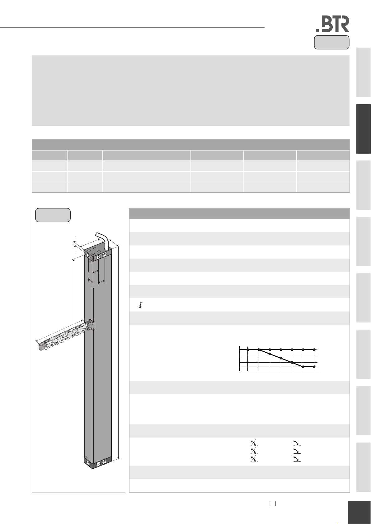
Snow load on roof windows for SHEV-systems
Example calculation
Establish snow loading based on national standards /directives
(in Germany according to DIN 1055-5)
total weight = FG + snow load
total weight = (40 kg + 60 kg) = 100 kg
Example:
snow load = 60 kg
(Casement area x
Typical snow load)
Example: FG = 40 kg

5
BDC Pro 24 V DC / 230 V AC
Preliminary remark
01
The casement measurements supplied
are only for orientation purposes.
It is imperative that the force-path
diagram of the drives are observed.
Note
Casement data
Facade: bottom-hung window / top-hung win-
dow / side hung window
Roof: roof window / sky light
Opening direction: inward opening / outward opening
Prole material: aluminum, steel, plastic or wood.
When inspecting the drives for conformity with on-site
requirements the following items must be observed:
• total weight of casement (glass + frame),
• additional loads: snow load / wind load
(suction / pressure),
• casement size (FAB x FAH),
• side ratio FAB / FAH,
• installation / inclination angle,
• required opening area (geometric / aerodynamic),
• crosswind inuences,
• driving force and stroke,
• mounting space at the window frame and casement
frame.
Hazard analysis according to DIN EN 60335-2-103
Contact-free anti-trap protection
(20.ZAA.8.1)
Passive infra-red and active light sensors
or
pressure mats
Contact-based anti-trap protection
(20.ZAA.8.2)
Pressure-sensitive safety switch strips
or
Motor current monitoring systems
(internal and external)
Hold-to-run switch:
stops movement at HSK < 20 mm
at a closing force of > 150 N at HSK
(20.ZAA.5)
Operating element in
direct range of vision:
a.) Key switch or
b.) other switch,
then: installation > 1,5 m,
inaccessible for public
(7.12.1)
Keep people away during closing!
Declaration of Conformity
power operated window
+ CE label
!
CaUtIon
Protection devices
!
CaUtIon
Use of the drive
NSHEV according to
EN12101-2 without
dual purpose for ventilation
NSHEV according to
EN12101-2 with
dual purpose for ventilation
(1.Z.109)
Natural ventilation
Installation height of drive and lower
edge of casement: > 2,5 m above oor
(ZAA.20.2)
Opening at HSK: < 200 mm and
Speed at HSK:
CLOSE <15 mm/s / OPEN < 50 mm/s
(20.ZAA.2)
Yes
Yes
No
No
No
risc assessment
required
Observe danger at NSK
< 2,5 m above oor!
!
CaUtIon
Keep people away during closing!
!
CaUtIon
Environment with children /
vulnerable people
The information in the brackets
refer to the chapters of DIN EN 60335-2-103.
Risk analysis according to the
Machinery Directive required
Casement data
Facade: bottom-hung window
top-hung window
side hung window
Roof: inward opening / outward opening
Opening direction: outward opening / inward opening
Prole material: aluminum, steel, plastic or wood

6
BDC Pro 24 V DC / 230 V DC AC
safety instruCtions
01
Danger spots by crush and shear points
Side-hung Bottom-hung Roof windows / skyskylight domes Louvre windows
Danger spots: crush and shear points according to DIN EN 60335-2-103
Note
Note
!
warNiNg
!
warNiNg
!
All devices must be permanently protected
from dirt and moisture, if the drive is not
explicitly suitable for use in wet areas (see
technical data).
Area of application
The drive shall only be used according to its intended use.
For additional applications consult the manufacturer or his
authorized dealer.
Mounting material
The required mounting material must to t with the drive
and occurring load and, if necessary, supplemented.
Installation
These instructions address expert and safety-conscious
electricians and / or qualied personnel knowledgeable in
electrical and mechanical drive installation.
Always check whether the system complies with current
regulations. Special attention must be paid to the opening
width, the opening area, the opening time and the opening
speed of the window, the temperature range of the drives /
external devices and cables as well as the cross section of
the connecting cables as function of the cable length and
power consumption.
All specications for installation must be checked indepen-
dently and, if necessary, adjusted at the installation site.
The connection assignment, the electrical supply data (see
product lable) and performance limits (see technical data)
as well as the mounting and installation instructions of the
drive must be strictly observed and adhered to!
Do not reach into the window rabbet or the operating
element (chain or spindle) during installation and opera-
tion! Ensure that, based on the installation position and
the opening movement of the casement, persons cannot
be trapped between the driven part of the window and
surrounding xed components (e.g. wall).
safety iNstruCtioNs
It is important to follow these instruc-
tions for the safety of persons. These
instructions shall be kept in a safe place
for the entire service life of the products.
Risk of crushing and entrapment!
Window can close automatically!
The integrated load cut-off stops the
drive during closing and opening when
the drive is overloaded.
The compressive force is absolutely
sufcient to crush ngers in case of
carelessness.
Do not misuse the drive for other lifting
operations!
Do not allow children to play with
this drive or its electric controls, including
the remote control!
The safe operation, avoidance of injury to
persons and damage to property, as well
as risks, is only guaranteed by proper
installation and setting according to
these installation instructions.
Before installing the drive, check whether
the casement is in good mechanical con-
dition, the weight in balance and whether
it opens and closes easily!
Never connect 24 V DC drives to 230 V AC
mains voltage!
Danger to life!

7
BDC Pro 24 V DC / 230 V AC
safety instruCtions
01
!
warNiNg
!
warNiNg
Crush and shear points
To avoid injuries, crushing and shear points between
casement and frame must be secured against entrapment
up to an installation height of 2,5 meters above the
oor with appropriate measures. This can be achieved e.g.
by using contact-based or contactless protective devices
against entrapment, which stop the motion through cont-
act or through interruption by a person. At a force higher
than 150 N at the main closing edge the motion must stop
within 20 mm. A warning symbol at the opening element
must indicate this clearly.
Unintentional or independent opening or falling
Casements are to be hinged or secured such way that in
case one of the mounting elements fails it will not crash /
slam down or move in an uncontrolled manner by e.g. using
double suspensions, safety scissors, casement stays.
Tilting windows shall be equipped with safety scissors or
similar devices to avoid damages and risks of injury for
persons through improper installation and operation. The
safety scissors must be adjusted to the opening stroke of
the drive (see technical data) to avoid blocking.The opening
width of the safety scissors must be bigger than the drive
stroke.
Routing cables and electrical connection
Routing or installing of electrical cables and connections
may be performed only by specialist companies. Never
operate drives, control units, operating elements and
sensors at operating voltages and connections contrary
to the specications of the manufacturer.
All relevant national instructions shall be observed for
the installation.
The types of cable, cable lengths and cross-sections shall
be selected in accordance with the manufacturer’s technical
data. If necessary, the cable types shall be coordinated with
the competent local authorities and energy supply com-
panies. Low-voltage lines (24 V DC) shall be routed
separate from the high-voltage lines. Flexible cables may
not be ush-mounted. Freely suspended cables shall be
equipped with strain reliefs.
Clamping points shall be checked for tightness of threa-
ded connections and cable ends. Access to junction boxes,
clamping points and external drive control boxes shall be
ensured for maintenance work.
Damaged mains supply lines of drives
with plug connectors may only be re-
placed by the manufacturer or qualied
service / maintenance personnel!
Power cables which are xed to the drive
casing cannot be replaced. If the cable is
damaged the device must be scrapped!
The movable casement must be secured
against unintentional or independent
opening as well as falling down.
All-pole disconnecting devices shall be instal-
led in the permanent electrical installation or
external Control Unit for the drive.
The mains supply lines 230 V / 400 V AC shall
be protected separately!
24V DC drives may only be connected to
power supply sources that comply with SELV
specications.
Cables must be laid such way that they can-
not be sheared off, twisted or bent during
operation. Drive cables laid inside window
proles must be protected by insulating
tubes with a sufcient temperature resistance.
Through holes shall be equipped with cable
sleeves!
safety scissors
In the case of tandem / multiple opera-
tion of drives connected in series, the
cross-section of the connection cable
must be checked autonomously, depen-
ding on the total current consumption of
the drive system.
Note

8
BDC Pro 24 V DC / 230 V DC AC
safety instruCtions
01
Note
Ambient conditions
The product may not be subjected to impacts or falls, or
to vibrations, moisture, aggressive vapors or other harmful
environments, unless the manufacturer released it for one
or more of these environmental conditions.
• Operation:
Ambient temperature: -5 °C … +60°C
Relative humidity: < 90% less 20°C;
< 50% less 40°C;
no formation of condensation
Observe temperature range during
installation!
• Transport / Storage:
Storage temperature: -5°C … +40°C
Relative humidity: < 60%
Accident prevention regulations and workmen’s
compensation insurance guidelines
For work on or in a building or building part the provisi-
ons and instructions of the respective accident prevention
regulations (local workmen’s compensation insurance
guidelines) shall be observed and adhered to.
Declaration of Conformity and of Incorporation
The drive is manufactured and inspected in accordance with
European guidelines. The respective Declaration of Con-
formity and of Incorporation is on hand.
In case that the use of the drive differs from the in-
tended use, a risk evaluation for the power operated
window shall be performed and a Declaration of Con-
formity according Machinery Directive 2006 / 42 / EG
issued.
Commissioning, operation and maintenance
After the installation and after each modication in the set
up all functions shall be checked with a trial run. It shall
be ensured that drive and casement are set correctly and
that security systems, if available, are functioning properly.
After the installation of the system is completed the
end-user shall be instructed in all important opera-
ting steps. If necessary, he must be advised of all remaining
risks / dangers.
The end-user shall be specically instructed that no
additional forces, except pushing and pulling forces in the
opening and closing direction of the casement, may be
applied to the spindle, chain or lever of the drive.
Note
Post warning signs!
Other persons must be kept away from
the casement when a hold-to-run switch
(pushbutton) is operated or when a
window, which has been opened by a
smoke and heat exhaust system, is clo-
sing!
The operating element of hold-to-run
switches must be installed within di-
rect view from the window, but apart
from moving elements. If the switch is
not a key-operated switch it must be
installed at a minimum height of 1,5 m
and inaccessible to the public!
Do not allow children to play with
permanently mounted control devices
and keep remote controls out of reach
for children!
!
CautioN
!
CautioN
!
CautioN
During cleaning, maintenance work and while
exchanging parts the drive must be comple-
tely disconnected from the power supply and
secured against unintentional reactivation.
During the proper assembly of drives with mounting
elements at a window, and the connection to an external
control unit, the interfaces resulting from mechanical and
electrical performance characteristics of single elements
shall be observed.
Replacement parts, fasteners and controls
The drive shall only be operated with control devices from
the same manufacturer. There is no liability, warranty or
customer service if third-party parts are used. Exclusively
original spare parts of the manufacturer shall be used for
mounting elements or expansions.
!
warNiNg
Do not actuate the drive or the case-
ment when repair or re-setting works are
performed!

9
BDC Pro 24 V DC / 230 V AC
s
13
13
12
143 5
41
26
L
24 V
24 V
Data sheet
Data sheet BDC Pro 24V DC
Application: natural ventilation and smoke and heat exhausting systems (SHEVS)
Internal intelligent control electronics
The programming of the drives in multi-drive occurs at factory
High-quality stainless steel sidebow roller chain, without protruding rivet heads
Options
Programmable special functions
Technical Data
UNRated voltage 24 V DC (19 V ... 28 V)
INRated current 0,8 A
IACut-off current 1,0 A
PNRated power 17 W
DC Duty cycle 5 cycles (ED 30 % - ON: 3 min. / OFF: 7 min.)
Protection rating IP 32
Ambient temperature range -5 °C ... +60 °C
FZPulling force max. 250 N
FAPushing force max. s > 600 mm only for pulling application
FHPullout force 1.800 N (fastening depended)
Chain Stainless steel, without protruding rivet heads.
Simple connection to casement brackets.
Small bending radii allow maximum opening angles
of small windows.
Connecting cable non-halogen, grey 3 x 0,5 mm², ~ 3 m
vSpeed s = 400 8,0 mm/s 8,0 mm/s
s = 600 12,0 mm/s 8,0 mm/s
s = 800 13,5 mm/s 8,0 mm/s
sStroke 400 mm + 600 mm + 800 mm
Sound pressure level: ≤70 dB (A)
Order Data
s [mm] L [mm] Version Finish PU / pcs. Part.-No.
400 430 BDC Pro 400 24 V E6 / C - 0 110.300
600 545 BDC Pro 600 24 V E6 / C - 0 110.301
800 625 BDC Pro 800 24 V E6 / C - 0 110.302
02
50
0
250
150
100
200
500400 600300200
s
(mm)
F
(N)
800 1000
Pull
Push

10
BDC Pro 24 V DC / 230 V DC AC
s
13
13
12
283
L
5
41
26
230 V
230 V
Data sheet BDC Pro 230V aC
Application: natural ventilation
Internal intelligent control electronics
Parallel connection up to 8 drives in one group
High-quality stainless steel sidebow roller chain, without protruding rivet heads
Options
Programmable synchronised run (max. 4 drives) and special functions
The programming of the drives in multi-drive occurs at factory
Technical Data
UNRated voltage 230 V AC (50 Hz)
INRated current 0,13 A
IACut-off current 0,2 A
PNRated power 30 W
DC Duty cycle 5 cycles (ED 30 % - ON: 3 min. / OFF: 7 min.)
Protection rating IP 32
Ambient temperature range -5 °C ... +60 °C
FZPulling force max. 250 N
FAPushing force max. s > 600 mm only for pulling application
FHPullout force 1.800 N (fastening depended)
Chain Stainless steel, without protruding rivet heads.
Simple connection to casement brackets.
Small bending radii allow maximum opening angles
of small windows.
Connecting cable non-halogen, grey - 6 x 0,75 mm², ~ 3 m
vSpeed 8,0 mm/s 8,0 mm/s
sStroke 400 mm + 600 mm + 800 mm
Sound pressure level: ≤70 dB (A)
Order Data
s [mm] L [mm] Version Finish PU / pcs. Part.-No.
400 570 BDC Pro 400 230 V E6 / C - 0 110.303
600 685 BDC Pro 600 230 V E6 / C - 0 110.304
800 765 BDC Pro 800 230 V E6 / C - 0 110.305
50
0
250
150
100
200
500400 600300200
s
(mm)
F
(N)
800 1000
Pull
Push
Data sheet
02

11
BDC Pro 24 V DC / 230 V AC
PreParing assembly
Note
exPlaNatioNs oN the ProDuCt laBel
The product label provides information on the most import-
ant caracteristics, such as:
• manufacturer‘s address
• article reference number and name
• technical caracteristics
• date of manufacturing with rmware version
• serial number
• certications
Never install and operate damaged
products.
In the event of any complaints, please indicate the
product serial number (SN) (see product label).
serial number
symbols see
„Technical data“ article reference
number
certicationsProduct designation
Exemplary representation
date of manufacturing
with rmware version
i
-5°C
+60°C
86672 Thierhaupten
Tel.: +49 8271 811 92-0
Made in Germany
Bottom-hung casement und Top-hung casement
inward opening
FAB min. = L + 100 mm
FAB >1,30 m = mount 2 drives
Bottom-hung casement und Top-hung casement
outward opening
FAB min. = L + 100 mm
FAB >1,30 m = mount 2 drives
aPPliCatioN areas aND CasemeNt sizes
Top-hung casement Top-hung casementBottom-hung casement Bottom-hung casement
02
(Casement size max. 4 m - depending on the system)

12
BDC Pro 24 V DC / 230 V DC AC
PreParing assembly
InstallatIon steP 1: iNsPeCtioN Before the iNstallatioN
It is imperative that the sufciently
mechanical stiffness of the fastener type
as well as of the swivel range of the drive
is observed.
If this is not guaranteed another type of
fastening or another type of drive must
be selected.
!
The support surface of the frame brackets or
casement brackets must rest completely on
the window or frame prole. There must be
no tilting of the fastening elements during
extension and retraction of the drives. A
safe and solid fastening must be ensured
at the window prole.
Storage of drives at the construction site
Protective measures against damages, dust, moisture or
contamination shall be taken. Store drives intermediately
only in dry and well ventilated rooms.
Inspection of drives before installation
Check drives and window before installation for good
mechanical condition and completeness. The chains / spind-
les of the drives must be extendable or retractable easily.
The casement must run smoothly and the weight must be
in balance.
The test procedure of drives may only be performed on a
non-slip and secured mat or a test xture. During the test
run the test element must not be interfered with. The test
my only be conducted by or under the supervision of expert
personnel.
For testing chain drives the chain must be extended and
retracted at an angle of approx. 90°. The spindle tubes of
spindle drives in round housing tubes must be secured
against independent spinning before starting the test to
avoid deviations in the integrated position encoder.
Inspection of the intended use
The planned use of the drive must be checked for com-
pliance with its intended use. If used otherwise the liability
and warranty claim expires.
Predictable misuse
It is imperative that foreseeable misuse of drives is avoided!
Here are a few examples:
• do not connect 24 V DC drives to a 230 V AC mains
voltage,
• observe synchronous run and sequence control by drives
with multiple interconnection (if existing),
• use drives only indoors,
• avoid additional force inuences, e.g. transverse forces.
Testing mechanical requirements
Prior to the start of the installation check whether :
• the support surface and the prole static for the load
transmission is sufcient,
• a support construction for the secure fastening of the
drives is required,
• cold bridges (thermal separation) are avoidable at
action points,
• there is sufcient space for the swivel movement of the
drive.
If not, counter measures must be taken!
!
CautioN
!
warNiNg
Important instructions for a safe instal-
lation. Observe all instructions, wrong
installation may result in serious injury!
03

13
BDC Pro 24 V DC / 230 V AC
Scope of delivery:
Prior to assembly, check items quantity in the delivery for
completeness.
Tools required
• Marker,
• Grains,
• Hammer,
• Screwdriver (slotted-head, cross or Torx)
size by site conditions,
• Hexagonal wrench size 3 / 4 / 5 / 6,
• Torque wrench,
• Power drill,
• Threadlock adhesive,
• possibly a tool for blind rivet nuts (size 6).
InstallatIon steP 2: iNstallatioN PrereQuisite aND iNstallatioN PreParatioN
The following conditions must be fullled for the instal-
lation of the drives so they can be properly assembled with
other parts and constructed to a complete machine at the
window without impairing the safety and health of persons:
1. The design of the drive must fulll the requirements.
2. The fastening accessories (casement brackets or
frame brackets) must t the window prole; the
prole-dependent hole lay-out must be complied with.
3. The space required for the installation of the drive on
the frame and casement prole must be sufcient.
4. The window must be in perfect mechanical condition
before the installation. It should open and close easily.
5. The fastening material for the installation of the drive
must t the window material (see table).
Check window data on site
• Measure FAB and FAH.
• Check / calculate weight of casement.
If unknown, it can be determined approximately with
the following formula:
• Check / calculate the required drive force and compare
with drive data . If unknown, it can be determined
approximately with the following formula:
a= Distance of action point to hinges
F= Drive force
s= Stroke
weight) [kg] [m] [m] [mm] frame
share
glass-
density
G (Casement = FAB *FAH *Glass thickness * 2,5 *1,1
F[N] =
Facade Roof
F[N] =
5,4 *G[kg] *s[m] 5,4 *G[kg] *FAH [m]
a[m] a[m]
Wood windows
Wood screws:
i.e. DIN 96, DIN 7996, DIN 571
round head with slot,
round head with cross,
hex head,special type
steel, stainless steel,
aluminum windows
Self-tapping screws, thread screws,
sheet-metal screws
i.e. ISO 4762, ISO 4017, ISO 7049 , ISO 7085, DIN 7500
cylinder head with hex socket, internal serration (Torx),
Phillips head or external hex head
blind rivet nut
plastic windows
Screws for plastic
i.e. DIN 95606, DIN 95607, ISO 7049,
ISO 7085, DIN 7500
round head with cross, external hex head,
Torx
Recommendation:
if possible, screw
through two cavity
webs
a
a
a
G
G
s
s
s
FAH
G
F
F
F
FAH
FAH
a
a
a
G
G
s
s
s
FAH
G
F
FF
FAH
FAH
a
a
a
G
G
s
s
s
FAH
G
F
F
F
FAH
FAH
Accessories: Chain drive BDC Pro
Assembly Instructions
Warning sign sticker
„Risk of entrapment“
Tools required
• Marker
• Grains
• Hammer
• Screwdriver (slotted-head, cross or Torx) SW 4
size by site conditions
• Hexagonal wrench (inside) size SW2,5
• Hexagonal wrench (outside) size SW5,5
• Torque wrench
• Power drill
• Threadlock adhesive
• possibly a tool for blind rivet nuts (size 6)
BDCPro 24 V DC
BDCPro 230 V AC
2
BDCPro 24 V DC
BDCPro 230 V AC
1BDCPro 24 V DC
BDCPro 230 V AC
4
BDCPro 24 V DC
BDCPro 230 V AC
3BDCPro 24 V DC
BDCPro 230 V AC
5
12 - 18
12
parallel
parallel
min. 8
parallel
42 ±2
15
parallel
90°
A
B
138
278
24V
230V
C
D
FABmin.: W= symmetrical / Y= asymmetrical
FABmin.:
X
= symmetrical /
Z
= asymmetrical
24V
230V
24V
230V
24V
230V
24V
230V
1/2FAB
26 9
28
15
21
Ø5,5
3
42
8
A
B
143,5
77
12 8
121/2FAB
20,5
10
6,5
283,5
123,5
263,5
C
D
FABmin.: W= symmetrical / Y= asymmetrical
FABmin.: X= symmetrical /Z= asymmetrical
24V
230V
24V
230V
24V
230V
24V
230V
24V
230V
24V
230V
55
16
12-18
9
50
9
min.
28
max. 35
21
15
Note the safety instructions!
Links to safety instructions,assembly instructions,
and manufacturer statements:
Please scan in the QR code and follow the link
to the BTR homepage.
9000000261_V0.1_KW20/20
www.btr-hamburg.de
BTRGMBH
Gemeindewald11
86672 Thierhaupten
Tel.+49 8271 811 92-0
Fax+ 49 8271811 92-55
BDB101 - Part.-No. 10.250
BDB104 - Part.-No. 10.350
BDC Pro (230V)
Multi-drive operation: BDC Pro (230V)
BDC Pro (24V)
Multi-drive operation: BDC Pro (24V)
24V
24V
230V
230V
1 3
BDC PRo
Assembly InstructIon
bDc Pro
according to Machinery Directive
2006/42/EG (annex VI)
ChainDrive for winDows
BDC Pro Part.-No. s (mm) L (mm)
BDC Pro 400 24V 10.300 400 430
BDC Pro 600 24V 10.301 600 545
BDC Pro 800 24V 10.302 800 625
BDC Pro 400 230V 10.303 400 570
BDC Pro 600 230V 10.304 600 685
BDC Pro 800 230V 10.305 800 765
2
Video-Link to the detailed assembly instructions
BDB101 BDB104
BDB101
BDB104 BDC PRo
24V DC
Stroke A C W Y
400 430 420 ≥570 ≥ 430
600 545 535 ≥800 ≥ 545
800 625 615 ≥960 ≥ 625
230V AC
Stroke B D X Z
400 570 560 ≥570 ≥ 570
600 685 675 ≥800 ≥ 685
800 765 755 ≥960 ≥ 765
24V DC
Stroke A C W Y
400 431 267,5 ≥ 570 ≥ 430
600 546 382,5 ≥ 800 ≥ 545
800 626 462,5 ≥ 960 ≥ 625
230V AC
Stroke B D X Z
400 571 267,5 ≥ 570 ≥ 570
600 686 382,5 ≥ 800 ≥ 685
800 766 462,5 ≥ 960 ≥ 765
s
13
13
12
5
41
26
24 V
230 V
143
283
L
M5
SW2,5
SW5,5
BDC PRo
M5
BDC PRo
BDC PRo
BDB101
BDB101
BDC Pro
BN
BK
BNL
OPEN CLOSE
BK
GN / YE
BU
= PE
= N
GY
WH
230 V
+
+
-
-
BDC Pro24 V
WH
BN
BU
BN
OPEN
Polarityreversal
CLOSE
BU
WH
GY
BU
BN BK
junctionbox
site-supplied
GN / YE
BK
BN
GN / YE BU
L-OPEN L-CLOSE PE N
BDC ProBDC Pro
Master Slave
230 V AC 230 V AC
+
+
-
-
BDC ProBDC Pro
Master Slave
WH
BN
BU
BN BU
BDL Uni
Polarity
reversal
junctionbox
site-supplied
24 V DC 24 V DC
12 9
5,5
28,5
12 21
41
25
5 6,5
32
40
ø5,5
ø5,5x9,5
15
14
M3x20
(SW 2,5)
M5x10
(SW 4)
42 9
60
4
M3x25 (SW2,5)
5,5
17
41
50
67
63
40
267
4Nm
max.
M5 (SW4)
BDC PRo
BDC PRo
BDB104
BDB104
BDB104
PreParing assembly
03
Scope of delivery:
Prior to assembly, check items quantity in the delivery for
completeness.

14
BDC Pro 24 V DC / 230 V DC AC
Drive positioning: Asymmetrical
Asymmetrical linkage of casement bracket or frame bracket can be
used in case of lack of space on the window frame / casement.
Drive positioning: Symmetrical
Symmetrical linkage of casement bracket or frame bracket
should always be preferred to an asymmetrical one.
Advantage:
• uniform force transmission to the window
• uniform casement pressure (tightness)
DriVe PositioNiNg: symmetriCal or asymmetriCal
!
Check:
• unequal force transmission to the window
• window statics allows unequal force distribution
• unequal casement pressure (tightness)
1/2 FAB
FAB
= =
FL
RA
==
FAB
1/2 FAB
FL
RA
Dimensions and Drill holes
Bracket-Set BDB101
(Part.-No.: 10.250)
Bracket-Set BDB104
(Part.-No.: 10.350)
InstallatIon steP 3: BraCket-sets (DimeNsioNs aND Drill holes)
Casement bracket Casement bracket
Frame bracket
Casement braCkets anD frame braCkets
0604
nsKHsK
BDC Pro
BDC Pro
BDB 101 BDB 101
M3x25 (SW2,5)
5,5
17
41
50
67
63
40
267
12 9
5,5
28,5
12 21
41
25
5 6,5
32
40
ø5,5
ø5,5x9,5
15
14
M3x20 (SW 2,5)
M5x10
(SW 4)
42 9
60
4

15
BDC Pro 24 V DC / 230 V AC
aPPliCation examPles
04
Bottom-hung casement inward opening (Application examples)
Rigid drive mounting directly on the window frame
Bracket-Set BDB 101 (without frame bracket)
Space on the frame = 28 mm
Rigid drive mounting on the casement
Bracket-Set BDB 104
Space on the frame = 16 mm
aPPliCatioN examPles
nsKHsK
50
9
min.
28
max. 35
21
15
BDC Pro BDB 101
reference edge
55
16
12-18
9
BDC ProBDB 104
reference edge

16
BDC Pro 24 V DC / 230 V DC AC
Bottom-hung casement inward opening -
Swiveling drive mounting on the casement - with Bracket-Set BDB 104
Bottom-hung casement inward opening
Rigid drive mounting directly on the window frame - with Bracket-Set BDB 101
hole layout for braCket-sets
0604
InstallatIon steP 4: hole layout for BraCket-sets
3
FL RA
42
8
A
B143,5
7 7
12 8
12
1/2 FAB
20,5
10
6,5
283,5
24 V
230 V
123,5 24 V
263,5 230 V
24 V
230 V
C
D
24 V
230 V
FAB min.: W= symmetrical / Y= asymmetrical
FAB min.:
X=
symmetrical /
Z=
asymmetrical
24 V 24 V
230 V230 V
A
B
138
278
24 V
230 V
24 V
230 V
C
D
24 V
230 V
FAB min.: W= symmetrical / Y= asymmetrical
FAB min.: X= symmetrical / Z= asymmetrical
24 V 24 V
230 V230 V
1/2 FAB
26 9
28
15
21
FL
RA
Ø 5,5
nsKHsK
When mounting two drives,
a minimum distance of 50 mm
between the drives is considered.
When mounting two drives,
a minimum distance of 50 mm
between the drives is considered.
Window versions:
Bottom-hung - inward opening
Top-hung - inward opening
Side-hung - inward opening
Window versions:
Bottom-hung - inward opening
Top-hung - inward opening
Side-hung - inward opening
24 V DC
Stroke A C W Y
400 431 267,5 ≥ 570 ≥ 430
600 546 382,5 ≥ 800 ≥ 545
800 626 462,5 ≥ 960 ≥ 625
24 V DC
Stroke A C W Y
400 430 420 ≥ 570 ≥ 430
600 545 535 ≥ 800 ≥ 545
800 625 615 ≥ 960 ≥ 625
230 V AC
Stroke B D X Z
400 571 267,5 ≥ 570 ≥ 570
600 686 382,5 ≥ 800 ≥ 685
800 766 462,5 ≥ 960 ≥ 765
230 V AC
Stroke B D X Z
400 570 560 ≥ 570 ≥ 570
600 685 675 ≥ 800 ≥ 685
800 765 755 ≥ 960 ≥ 765
BDC Pro
BDC Pro
BDB 104
BDB 101
reference edge
reference edge

17
BDC Pro 24 V DC / 230 V AC
mounting
FL RA
90°
FL
RA
FL RA
15
parallel
InstallatIon steP 5a:
Screw the Bracket-Set BDB 101 onto casement
(M5). If required, use washers.
Secure chain in the Bracket-Set BDB 101 with the
enclosed screw and nut .
„Casement bracket“ center and „chain out-
put“ must be in line.
Connect control voltage of the drive BDC Pro
(e.g. using a tester).
Move out the chain of drive BDC Pro approx. 100
to 150 mm.
Note For multi-drive operation actuate all drives
BDC Pro together.
Note cable routing!
(see chapter: CaBle routiNg)
Note soft run mode!
(see chapter: soft ruN moDe)
Check swiveling area! (see chapter:
safety CheCk aND PerformiNg test ruN).
Inward opening windows
Carefully clear away drilling swarfs to prevent
seals from being damaged.
Avoid surface scratches, for example by using
masking tape.
Secure fasteners against loosening; e.g. by applying
removable thread-locking compound such as “Loctite”.
Screw the drive BDC Pro onto window frame (M5).
Make sure it is parallel to casement edge.
The drive body must lie completely ush on
the window frame surface.
Directly on the window frame - main closing edge or auxillary closing edge
rigiD DriVe mouNtiNg with BraCket-set BDB 101
M5
SW 2,5
SW 5,5
reference edge
Determine fastenings for drive BDC Pro and
Bracket-Set BDB 101 .
Produce drill holes with appropriate cross-section (For
mounting dimensions see drill holes „InstallatIon stepe 3
and 4“ or project-specic documents and drawings).
Note Screws - for mounting on the window - are to
be provided by the customer!
nsKHsK
05
BDC Pro
1
2
on-site
M5
BDC Pro 1
on-site
2
3
4
LOCTITE

18
BDC Pro 24 V DC / 230 V DC AC
mounting
FL
RA
FL
RA
parallel
min. 8
42 ±2
12 - 18
12
FL
RA
parallel
parallel
FL
RA
RA
InstallatIon steP 5B:
Note cable routing!
(see chapter: CaBle routiNg)
Note soft run mode!
(see chapter: soft ruN moDe)
Check swiveling area! (see chapter:
safety CheCk aND PerformiNg test ruN).
Connect control voltage of the drive BDC Pro
(e.g. using a tester).
Move out the chain of drive BDC Pro approx. 100
to 150 mm.
Note For multi-drive operation actuate all drives
BDC Pro together.
Inward opening windows
Screw the casement bracket of BDB104 onto the
window frame (M5).
Screw the frame bracket of BDB104 onto the
casement (M5).
Make sure it is parallel to casement edge.
„Casement bracket“ center and „chain out-
put“ must be in line.
On the casement - main closing edge or auxillary closing edge
rigiD DriVe mouNtiNg - BraCket-set BDB 104
Determine fastenings for Bracket-Set BDB 104 / .
Produce drill holes with appropriate cross-section (For
mounting dimensions see drill holes „InstallatIon stepe 3
and 4“ or project-specic documents and drawings).
Note Screws - for mounting on the window - are to
be provided by the customer!
Drilling swarfs should not damage seals and
surfaces.
Secure fasteners against loosening.
Note If required, use washers corresponding to the
used screws.
Attach drive BDC Pro to the frame brackets .
Secure the drive BDC Pro with the enclosed
thread-grooving screws .
2
3
Secure chain in the casement bracket with the
screw
(pay attention to the thread side).
max. 4 Nm
Thread-forming screws
are delivered with the
Bracket-Set BDB 104 .
3
5
reference edge
M5
M5 (SW4)
on-site
M5
on-site
BDC Pro 1
2
BDC Pro
BDC Pro 1
4
23
0605
nsKHsK

19
BDC Pro 24 V DC / 230 V AC
Upon removal of the glazing bead is the
danger that the glass may fall.
Cable crossover without
protective cable hose
Cable crossover with
protective cable hose
Connection cable routing on the hinge side:
• Make sure that during opening or closing procedure the cable will
not be damaged by shearing-off, kinking, crushing.
• Protect cable feedthrough in prole e.g. by using cable bushings,
cable transitions.
Cable on casement Cable in glazing bead
Cable duct glued on
(in addition secured with coun-
tersunk screws against breaking
away)
Drill hole in glazing bead
(cable bushing protects against
damage to cable).
Connection cable routing on the frame or transom:
• Cable must be protected against damage (shearing-off, kinking,
splitting), i.e. by using bushings.
Cable routing
InstallatIon steP 6: CaBle routiNg
FL RA
FL RA
06
BD BD protective
cable hose
AK
BDC ProBDC Pro

20
BDC Pro 24 V DC / 230 V DC AC
Make sure when establishing the connection
that there is no voltage at the terminals!
Unused wires must be safely insulated!
InstallatIon steP 7: eleCtriC CoNNeCtioN
Direction of travel
OPEN
CLOSE
Polarity reversal
+
+
-
-
Wire colour coding
Colour DIN IEC 757
black BK
brown BN
blue BU
green / yellow GN / YE
grey GY
white WH
Multi-drive operation:
Opening drive is done by master / slave
The programming of the drives in multi-drive occurs at factory.
WH: is used for communication,
with synchronized multi-drive operation.
WH connection, otherwise no function.
Optional: to 4 drives and max. 2 locking drives are possible.
Multi-drive operation:
Opening drive is done by master / slave
The programming of the drives in multi-drive occurs at factory.
WH: is used for communication,
with synchronized multi-drive operation.
WH connection, otherwise no function.
Optional: to 4 drives and max. 2 locking drives are possible.
The running direction of the 24V-drive may be changed
by interchanging (polarity reversal) the wires „BN -
(brown)“ - „BU - (blue)“.
No voltage on white wires (WH) - drives can
be damaged!
eleCtriC ConneCtion
Connection assignment
WH: is used for communication,
with synchronized multi-drive
Connection assignment
WH: is used for communication,
with synchronized multi-drive
0706
+
+
-
-
24 V DC
BDC Pro
WH
BN
BU
BN
OPEN
Polarity reversal
CLOSE
BU
24 V
24 V 230 V
230 V
230 V AC
BDC Pro
BN
BK
BNL
OPEN CLOSE
BK
GN / YE
BU
= PE
= N
GY
WH
+
+
-
-
24 V DC 24 V DC
BDC ProBDC Pro Master Slave
WH
BN
BU
BN BU
BDL Uni
Polarity
reversal
junction box
site-supplied
BDC ProBDC Pro
230 V AC 230 V AC
Master Slave
WH
GY
BU
BN BK
junction box
site-supplied
GN / YE
BK
BN
GN / YE BU
L-OPEN L-CLOSE PE N
This manual suits for next models
11
Table of contents
Popular DC Drive manuals by other brands

Granite Devices
Granite Devices EHTHERFOX quick start guide

Aerotech
Aerotech XC4 Hardware manual

Maxon
Maxon IDX 70 user manual

Aerotech
Aerotech Ndrive QL Series Hardware manual

Leadshine
Leadshine DM Series Hardware installation manual

Pacific Scientific
Pacific Scientific 6430 Installation & hardware reference manual