Bucher JMX-15P11-R1A0 User manual

User manual
JMX-15P11-R1A0
Supply unit
60887566_00

Bucher Automation AG has created this document with the requisite care and based on the current state of tech-
nology. Changes and further technical developments to our products are not automatically made available in a
revised document. Bucher Automation AG shall accept no liability or responsibility for errors of content or form,
missing updates or any damage or disadvantages arising therefrom.
Bucher Automation AG
Thomas-Alva-Edison-Ring 10
71672 Marbach/Neckar, Germany
T +49 7141 2550-0
Technical hotline
T +49 7141 2550-444
Sales
T +49 7141 2550-663
www.bucherautomation.com
Translation of the german original User Manual
Revision 1.00
Date of issue 9/6/2023

Bucher Automation AG Table of contents
User manual – JMX-15P11-R1A0 iii
Table of contents
1 Introduction................................................................................................................................................. 5
1.1 Information on this document ............................................................................................................. 5
1.2 Typographical conventions................................................................................................................. 5
2 Safety........................................................................................................................................................... 6
2.1 General Information............................................................................................................................ 6
2.2 Purpose .............................................................................................................................................. 6
2.2.1 Intended use.......................................................................................................................... 6
2.2.2 Non-intended use .................................................................................................................. 6
2.3 Warnings used in this document ........................................................................................................ 7
2.4 General safety instructions ................................................................................................................. 8
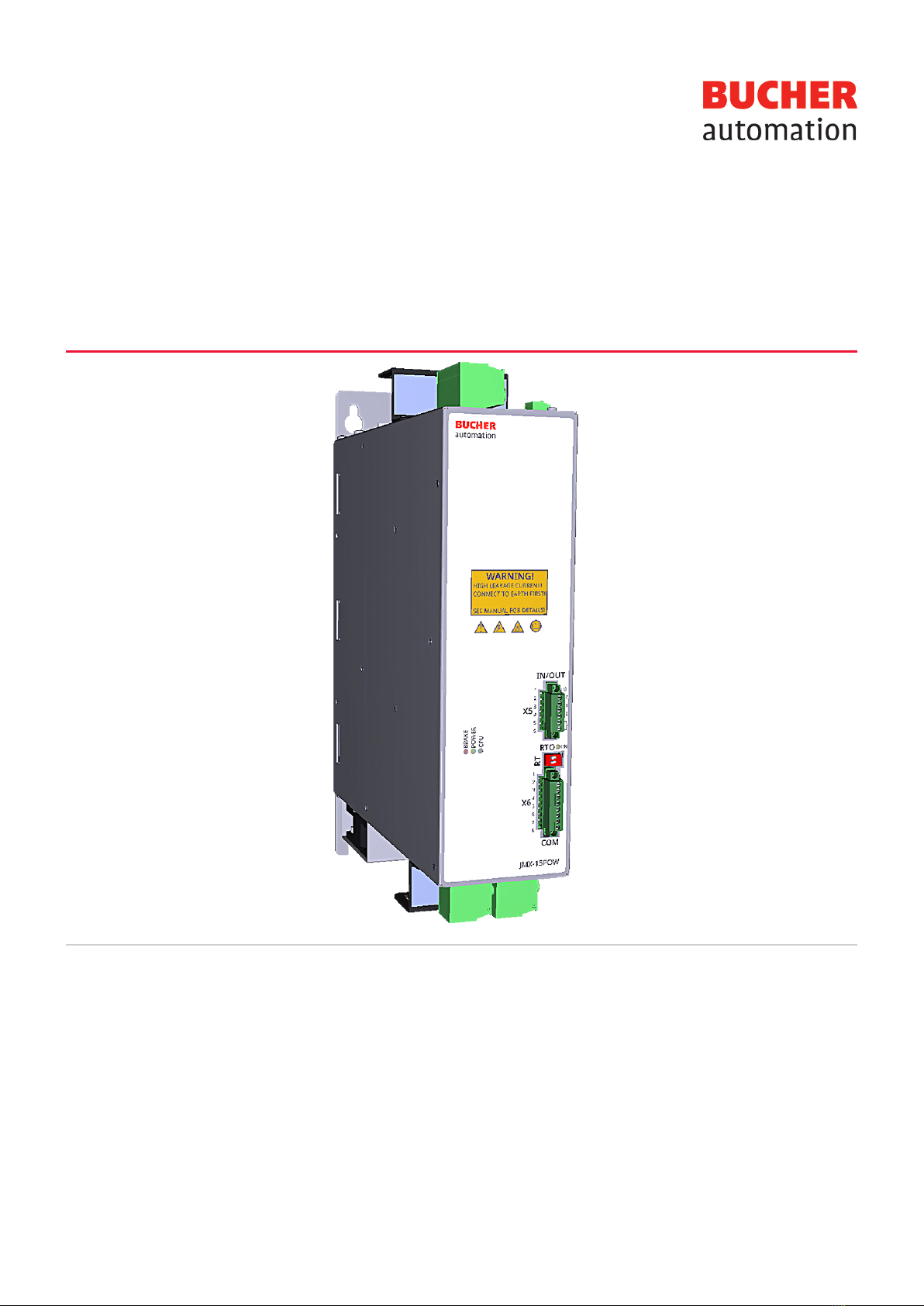
3 Product description.................................................................................................................................... 11
3.1 System overview ................................................................................................................................ 12
3.2 Design ................................................................................................................................................ 13
3.3 Product features ................................................................................................................................. 14
3.4 Status display ..................................................................................................................................... 14
3.4.1 Lighting patterns of the LEDs ................................................................................................ 14
3.4.2 Status display LEDs .............................................................................................................. 15
3.5 Nameplate .......................................................................................................................................... 16
3.6 Scope of delivery ................................................................................................................................ 17
4 Technical data............................................................................................................................................. 18
4.1 Dimensions......................................................................................................................................... 18
4.2 Mechanical specifications................................................................................................................... 19
4.3 Electrical properties ............................................................................................................................ 19
4.4 Torque reduction ................................................................................................................................ 24
4.5 Environmental conditions ................................................................................................................... 25
5 Mechanical installation .............................................................................................................................. 26
5.1 Installing the supply unit ..................................................................................................................... 26
5.2 Dismantling the supply unit................................................................................................................. 27
6 Electrical connection ................................................................................................................................. 28
6.1 Power supply ...................................................................................................................................... 30
6.1.1 Connection of voltage supply and RTO contact .................................................................... 30
6.2 Block diagram..................................................................................................................................... 31
6.3 Test installation................................................................................................................................... 31
6.4 Connection example........................................................................................................................... 33
6.4.1 Line cross-sections................................................................................................................ 34
6.5 Input connection ................................................................................................................................. 34

Bucher Automation AG Table of contents
User manual – JMX-15P11-R1A0 iv
6.5.1 Fuses..................................................................................................................................... 35
6.5.2 Power chokes ........................................................................................................................ 35
6.6 Output connection .............................................................................................................................. 36
6.7 Incorrect connections ......................................................................................................................... 37
6.8 Charging circuit and start phase......................................................................................................... 39
6.8.1 Correct functioning of the charging circuit ............................................................................. 39
6.9 Protective conductor connection ........................................................................................................ 41
6.10 Connection X1 – braking resistor connection ..................................................................................... 42
6.11 Connection X2 - three-phase voltage supply...................................................................................... 43
6.12 Connection X3 - control section voltage supply.................................................................................. 43
6.13 Connection X5 - I/O interface ............................................................................................................. 44
6.13.1 Functions of the I/O resources .............................................................................................. 44
6.13.2 RTO contact .......................................................................................................................... 45
6.14 Connection X7 and X8 - output power................................................................................................ 45
7 Control elements ........................................................................................................................................ 46
7.1 Grounding capacitor switch SW1 ....................................................................................................... 46
8 Logical states of the power supply unit................................................................................................... 47
9 Errors and warnings................................................................................................................................... 49
9.1 Error description ................................................................................................................................. 49
9.2 Reset error.......................................................................................................................................... 49
9.2.1 Preconditions......................................................................................................................... 49
9.3 Error list .............................................................................................................................................. 51
10 Service......................................................................................................................................................... 56
10.1 Customer service................................................................................................................................ 56
11 Maintenance................................................................................................................................................ 57
11.1 Repairs ............................................................................................................................................... 58
11.2 Storage and shipment ........................................................................................................................ 58
11.3 Return and disposal............................................................................................................................ 58
12 Order code .................................................................................................................................................. 59

Bucher Automation AG Introduction | 1
User manual – JMX-15P11-R1A0 5
1 Introduction
1.1 Information on this document
This document forms an integral part of the product and must be read and understood
prior to using it. It contains important and safety-related information for the proper use
of the product as intended.
Target groups This document is intended for specialists with appropriate qualifications.
Only competent and trained personnel is allowed to put this device into operation.
During the whole product life cycle, safe handling and operation of the device must be
ensured. In the case of missing or inadequate technical knowledge or knowledge of this
document any liability is excluded.
Availability of
information
Make sure this document is kept at the ready in the vicinity of the product throughout its
service life.
For information on new revisions of this document, visit the download area on our web-
site. This document is not subject to any updating service.
Start | Bucher Automation - We automate your success.
For further information refer to the following information products:
– JetSym software Online Help
Detailed description of software functions with application examples
– Application-oriented manuals
Cross-product documentation
– Version updates
Information about new versions of software products or of the operating system of
your device
INFO EtherCAT®
EtherCAT® is a registered trademark and patented technology, li-
censed by Beckhoff Automation GmbH, Germany.
1.2 Typographical conventions
This manual uses different typographical effects to support you in finding and classify-
ing information. Below, there is an example of a step-by-step instruction:
üThis symbol indicates requirements which have to be met before executing the fol-
lowing action.
►This sign or a numbering at the beginning of a paragraph marks an action instruc-
tion that must be executed by the user. Execute the instructions one after the
other.
ðThe target after a list of instructions indicates reactions to, or results of these ac-
tions.
INFO Further information and practical tips
In the info box you will find helpful information and practical tips
about your product.

Bucher Automation AG Safety | 2
User manual – JMX-15P11-R1A0 6
2 Safety
2.1 General Information
When placed on the market, this product corresponds to the current state of science
and technology.
In addition to the operating instructions, the laws, regulations and guidelines of the
country of operation or the EU apply to the operation of the product. The operator is re-
sponsible for compliance with the relevant accident prevention regulations and gener-
ally accepted safety rules.
2.2 Purpose
2.2.1 Intended use
The supply unit JMX-15P11-R1A0 is a component designed for installation in industrial
and commercial plants and machines.
Installation is only permitted in stationary equipment. The JM-15 series multi-axis mo-
tion system consists of at least one supply unit and at least one servo amplifier. In mo-
tor operating mode, the supply unit draws power from the supply network and provides
it to the connected servo amplifiers via the DC link.
When the supply unit is installed in a machine, commissioning (i.e. commencement of
intended use) is prohibited until it has been determined that the machine complies with
Machinery Directive 2006/42/EC. Commissioning (i.e. commencement of intended use)
is only permitted if the EMC Directive (2014/30/EU) is complied with.
2.2.2 Non-intended use
Use of the supply unit outside of the application areas given here or under operating
ranges and ambient conditions other than those described in the documentation is con-
sidered non-intended use.
– The supply unit must not be used outside a control cabinet.
– Servo amplifiers from other manufacturers must not be operated on the supply
unit.
The following application areas are considered non-intended use:
– Installation in vehicles. Use of the device in non-stationary equipment is consid-
ered an exceptional environmental condition and is only permitted after special
agreement.
– Installation in environments where there are hazardous oils, acids, gases, vapors,
dusts, rays, etc.
– Use in special application areas (e.g. where there is a risk of explosion, corrosion
or fire).
– Untypical generation of higher frequency on-board networks.

Bucher Automation AG Safety | 2
User manual – JMX-15P11-R1A0 7
2.3 Warnings used in this document
DANGER
High risk
Indicates an imminently hazardous situation which, if not avoided,
will result in death or serious injury.
WARNING
Medium risk
Indicates a potentially hazardous situation which, if not avoided,
could result in death or serious injury.
CAUTION
Low risk
Indicates a hazardous situation which, if not avoided, could result
in minor or moderate injury.
NOTICE
Material damage
Indicates a situation which, if not avoided, could result in malfunc-
tions or material damage.

Bucher Automation AG Safety | 2
User manual – JMX-15P11-R1A0 8
2.4 General safety instructions
DANGER
Risk due to high electrical voltage
Touching live parts may result in death or severe injury.
► Carry out the following steps before starting work to ensure
safety.
þPrepare for turning off the system. Inform everyone involved
who will be affected by the process.
þIsolate the drive system from the power supply and secure it
against being turned on again.
þWait for the discharge time (approx. 10 minutes) and check all
power connections to ensure they are at zero potential.
þGround according to requirements.
þCover over neighboring live parts.
þEnsure the drives cannot move.
þDepressurize the compressed air lines and ensure that the
pressure is released.
DANGER
Risk of electric arc due to improper handling
Improper handling can result in an electric arc, which may lead to
severe injury or death.
► Open the plug connections only in de-energized state.
► Install the device only in an environment where there is no
risk of fire, without any flammable gases or vapors.
► Observe the specified limit values for voltage.
► Wire according to regulations.
WARNING
Risk of fire due to improper operation of the device
In case of improper operation or due to an error, the device may
overheat and cause a fire that may result in serious personal in-
jury or death.
► Operate the device according to the specification. Never ex-
ceed the maximum speed.
► Do not use any damaged devices.
► Turn off the device immediately if the temperature is too high.

Bucher Automation AG Safety | 2
User manual – JMX-15P11-R1A0 9
WARNING
Risk of crushing due to uncontrolled axis movements
High mechanical forces due to axis movements and accelera-
tions.
► Keep out of the hazard zone of the machines.
► Do not disable any safety equipment.
► Have malfunctions eliminated by qualified personnel.
WARNING
Risk of burns due to hot surfaces
The device may become hot during operation and can cause
burns if touched.
► Take protective measures to prevent inadvertent contact with
the device, e.g. protective covers.
► Make sure that no temperature-sensitive parts, e.g. connec-
tion cables, are attached or fastened to the device.
► Ensure there is adequate heat dissipation and maintain the
required distances during installation so as not to prevent or
restrict ventilation.
► Allow the device to cool off for a while before carrying out
cleaning or maintenance work.
► Wear personal protective equipment.
► Avoid all contact with the braking resistor.
► Do not place any flammable or heat-sensitive components in
the vicinity of the braking resistor.
► In critical cases, check the temperature of the braking resistor
during a test work cycle.
WARNING
Danger for persons with heart pacemakers and implants!
Electromagnetic fields are generated during operation. Electrical,
magnetic and electromagnetic errors endanger especially persons
with heart pacemakers or implants.
► You must not be in the immediate vicinity of the device if you
belong to the above group of persons.
► As an affected person, maintain a minimum distance of
300mm from the device.

Bucher Automation AG Safety | 2
User manual – JMX-15P11-R1A0 10
NOTICE
Material damage due to loose power connection
Vibrations or insufficient tightening torques can lead to loose
power connections. This can lead to fire damage, defects in the
device or malfunctions.
► Tighten all power connections to the specified tightening
torques.
► Check all power connections at regular intervals, especially
after transport.

Bucher Automation AG Product description | 3
User manual – JMX-15P11-R1A0 11
3 Product description
The JMX-15P11-R1A0 supply unit was developed for the supply of drives of the JMX
series.
The software with which the JMX-15P11-R1A0 supply unit is equipped is divided into
two types:
–Boot firmware: This boots the supply unit by activating a set of basic services,
and, after an initial phase of identification and diagnostics of the system, runs the
firmware
–Firmware: This manages all the operating functions of the supply unit

Bucher Automation AG Product description | 3
User manual – JMX-15P11-R1A0 12
3.1 System overview
IP 20 components housed in control cabinet
IP 65 components on machine
Servo amplifier
JM-3000
Supply
JMX-15Pxx
EtherCAT® bus node
JX3-BN-EC
Software
JetSym
Servo motor
1-cable technology
Distributed drive
JMXyy-15xxx
Line filter
JEMCxx.xxx-UR
Ethernet TCP/IP
Controller
JC-440MC
Klemmkasten
EtherCAT®
EtherCAT®
Ethernet TCP/IP
Terminal box
Fig.1: System overview

Bucher Automation AG Product description | 3
User manual – JMX-15P11-R1A0 13
3.2 Design
11
9
8
7
6
5
3
2
1
4
11
10
12
Fig.2: Design
1 Socket X2: Three-phase power supply
2 Nameplate
3 Connection of the grounding cable
4 Mounting plate
5 Screw for external braking resistor shield
6 Socket X1: Braking resistor
7 Socket X5: I/O interface, RTO contact
8 Socket X6: RS485, n. c.*
9 Socket X8: Output power for channel CH2
10 Socket X7: Output power for channel CH1
11 LEDs
12 Socket X3: 24V supply of the controller
*n. c. = not connected (= no function)

Bucher Automation AG Product description | 3
User manual – JMX-15P11-R1A0 14
3.3 Product features
– The JMX-15P11-R1A0 was developed for the supply of drives of the JMX series
– Built-in overcurrent protective devices
– The DC voltage properties of the DC link are suitable for drives of the JMX series
– Integrated protective functions
– Overload on the outputs of the DC bus
– Short circuit in the brake circuit
– Brake energy overload
– Charging energy overload
– Undervoltage/overvoltage/excessive ripple of the DC bus
– Overtemperature in the power and control section
3.4 Status display
BRAKE
POWER
CPU
Fig.3: Status display
ON
RTO
Fig.4: Status display
RTO
LEDs indicate the communication status of the device as well as the status of the
power supply.
Color and status of the LEDs are an excellent source of information for analyzing vari-
ous states.
The LEDs are located on the front of the JMX-15P11-R1A0.
3.4.1 Lighting patterns of the LEDs
Parameter Lighting pattern Description
OFF - LED turned off
ON Continuously lit LED turned on
BLK 200ms on, 200ms off Slow continuous flashing
Tab.1: Flashing patterns of the LEDs

Bucher Automation AG Product description | 3
User manual – JMX-15P11-R1A0 15
3.4.2 Status display LEDs
LED Color Action Description
BRAKE OFF --- Braking chopper not active
Orange ON Braking chopper active, energy
<50% of the maximum tolerable
value
Red ON Braking chopper active, energy
≥50% of the maximum tolerable
value
POWER OFF --- Turned off or in boot mode
Green BLK Start sequence (voltage/current
monitoring)
Green ON Ready to operate, output current
<70%Inom.
Green and orange BLK Ready to operate, output current
≥70%Inom.
Orange ON Device functions, one or several
warnings active
Red ON No voltage, one or several errors ac-
tive
CPU OFF --- CPU not working
Green ON CPU in firmware mode
Orange ON CPU in boot mode
Red ON CPU in reset
RTO OFF --- Contact open
Green ON Contact closed
Tab.2: Interpretation of the status of the LEDs

Bucher Automation AG Product description | 3
User manual – JMX-15P11-R1A0 16
3.5 Nameplate
1 2 3
4
5
6
7
Fig.5: Nameplate
1 Company logo
2 Warning signs and mandatory signs
3 Power data
UIN Input voltage range
IInMax Maximum input current
UOut Output voltage range
POutMax Maximum output power
IOutMax Maximum output current
UCtr Control voltage
ICtr Power consumption on control
voltage side
TAAmbient temperature
HW Hardware revision
IP Degree of protection
4 Serial number
5 Barcode of the serial number
6 Item number
7Item name (see Order code [}59])

Bucher Automation AG Product description | 3
User manual – JMX-15P11-R1A0 17
3.6 Scope of delivery
Scope of delivery Item number Quantity
JMX-15P11-R1A0 60886837_00 1
Phoenix connector plug
X1 3-pin 1
X2 4-pin 1
X3 3-pin 1
X5 6-pin 1
X7 2-pin 1
X8 2-pin 1
USB stick with complete documentation 1
Cables are not included in the scope of delivery.
Cables and other accessories are available from Bucher Automation AG.

Bucher Automation AG Technical data | 4
User manual – JMX-15P11-R1A0 18
4 Technical data
This chapter contains electrical, mechanical data and operating data of the
JMX-15P11-R1A0.
4.1 Dimensions
82.5
270.3
50
352.5
266.5
258.1
4 x Ø 6.5
332
Fig.6: Dimension in mm
INFO CAD data
CAD data of the device can be found in the download area of our
homepage.

Bucher Automation AG Technical data | 4
User manual – JMX-15P11-R1A0 19
4.2 Mechanical specifications
Parameter Description Standards
Mounting orientation Vertical
Weight 5.8 kg
Housing specifications
Material Metal
Cooling External fan
Vibration strength
Frequency sweeps 1octave/minute,
sinusoidal
DINEN61131-2
DINEN60068-2-6
Constant acceleration 2 g 5Hz ≤ f ≤ 500Hz
Number and direction 10 sweeps for all 3 spatial axes
Shock resistance
Type of shock Half-sine wave DINEN61131-2
DINEN60068-2-27
Intensity and duration 20g for 11ms
Number and direction 3 shocks in both directions of the 3 spatial axes
Degree of protection
Degree of protection IP20 DINEN60529
Tab.3: Mechanical specifications
4.3 Electrical properties
Power range Parameter Rated voltage
(min)
Rated voltage Rated voltage
(max)
Three-phase rated
voltage
AC230V AC400V AC480V
Type of earthing sys-
tem
Must connect to a TT network or TN network.
System voltage (rated
voltage between phase
and ground)
300V max
Installation categoryIII
Input voltage range 180…520V(50/60Hz)
Mains voltage unbal-
ance
<3%of input voltage
Short circuit rated cur-
rent of the line
5kA max
Line filter Integrated

Bucher Automation AG Technical data | 4
User manual – JMX-15P11-R1A0 20
Parameter Rated voltage
(min)
Rated voltage Rated voltage
(max)
Mains fuses
(to be provided by
user)
SIBA 50 124 06.32
Alternative fuses (CE):
– Bussmann cod. FWP-32A14F
– ITALWEBER AQS-F14x51 cod.1480032 or
other fuses providing 32A rating, fast-switching with
I2T≤700A2s
Power contactor
(to be provided by
user)
Three power terminals NO + 24Vdc coil, IEC 60947 compli-
ant or with Schneider series LC1D40 (UL)
Input current 22Aeff 24Aeff 21Aeff
Input current with line
inductance
(to be provided by
user)
- 17Aeff -
Output rated
voltage
DC324V DC564V DC677V
Output rated current
(CH1+ CH2)
20A 20A 16.7A
Output current (max)
(≤5s)
40A 40A 33.4A
Output rated
power
6.5kW 11.3kW 11.3kW
Output power pulse
(≤5s)
13kW 22.6kW 22.6kW
Current of each individ-
ual output channel
20A
DC link capacity 1000µF
Heat dissipation
(w/o consideration of
braking chopper power
dissipation)
100W
Tab.4: Power range data
Table of contents
Other Bucher Power Supply manuals