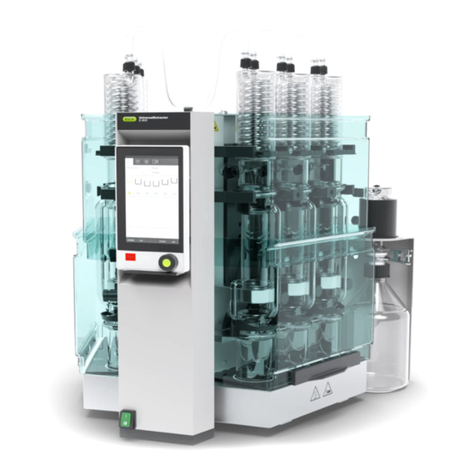
Buchi E-800 User manual

UniversalExtractor E-800
Operation Manual
11593959 | A en

Imprint
Product Identification:
Operation Manual (Original) UniversalExtractor E-800
11593959
Publication date: 02.2019
BÜCHI Labortechnik AG
Meierseggstrasse 40
Postfach
CH-9230 Flawil 1
E-Mail: [email protected]
BUCHI reserves the right to make changes to the manual as deemed necessary in the light of experi-
ence, especially with respect to structure, illustrations and technical details.
This manual is copyrighted. Information from it may neither be reproduced, distributed, or used for com-
petitive purposes, nor made available to third parties. The manufacture of any component with the aid of
this manual without prior written agreement is also prohibited.

BÜCHI Labortechnik AG Table of contents
Operation Manual UniversalExtractor E-800 iii
Table of contents
1 About this document...........................................................................................................7
1.1 Warning notices in this document........................................................................................................ 7
1.2 Symbols............................................................................................................................................... 7
1.2.1 Warning symbols .....................................................................................................................7
1.2.2 Mark-ups and symbols.............................................................................................................8
1.3 Trademarks.......................................................................................................................................... 8
2 Safety....................................................................................................................................9
2.1 Proper use ........................................................................................................................................... 9
2.2 Use other than intended ...................................................................................................................... 9
2.3 Staff qualification ................................................................................................................................. 9
2.4 Location of warning signs on the product .......................................................................................... 10
2.5 Protection devices ............................................................................................................................. 11
2.6 Residual risks .................................................................................................................................... 11
2.6.1 Hot surfaces...........................................................................................................................11
2.6.2 Empty beakers on heating plates........................................................................................... 11
2.6.3 Mechanical damages.............................................................................................................11
2.6.4 Glass breakage......................................................................................................................12
2.6.5 Glass damages during extraction process.............................................................................12
2.6.6 Overfilled extraction beakers .................................................................................................12
2.7 Personal protective equipment .......................................................................................................... 12
2.8 Modifications...................................................................................................................................... 12
3 Product description...........................................................................................................13
3.1 Description of function ....................................................................................................................... 13
3.1.1 Economic Continuous Extraction (without chamber heater).................................................. 13
3.1.2 Soxhlet Extraction (with and without chamber heater)........................................................... 14
3.1.3 Continuous Extraction (with and without chamber heater) ....................................................14
3.1.4 Hot Extraction (with chamber heater) ....................................................................................15
3.1.5 Soxhlet Warm Extraction (with chamber heater) ...................................................................15
3.1.6 Twisselmann Extraction (with chamber heater).....................................................................16
3.1.7 Description of the analyte protection...................................................................................... 16
3.2 Configuration ..................................................................................................................................... 17
3.2.1 Front view (with chamber heater) ..........................................................................................17
3.2.2 Front View (without chamber heater).....................................................................................18
3.2.3 Rear view ...............................................................................................................................19
3.2.4 Upper connections on the rear side....................................................................................... 19
3.2.5 Lower connections on the rear side....................................................................................... 20
3.3 Type plate.......................................................................................................................................... 20
3.4 Scope of delivery ............................................................................................................................... 21
3.5 Technical data ................................................................................................................................... 21
3.5.1 UniversalExtractor E-800 .......................................................................................................21
3.5.2 Ambient conditions.................................................................................................................21
3.5.3 Materials ................................................................................................................................22
4 Transport and storage ......................................................................................................23
4.1 Transport ........................................................................................................................................... 23
4.2 Storage .............................................................................................................................................. 23
4.3 Lifting the instrument ......................................................................................................................... 23

Table of contents BÜCHI Labortechnik AG
iv Operation Manual UniversalExtractor E-800
5 Installation..........................................................................................................................25
5.1 Before installation .............................................................................................................................. 25
5.2 Installation site................................................................................................................................... 25
5.3 Establishing electrical connections.................................................................................................... 25
5.4 Securing against earthquakes ........................................................................................................... 26
5.5 Connecting the coolant hose ............................................................................................................. 26
5.6 Connecting the solvent tubes to the condenser tank bottle............................................................... 27
5.7 Connecting the coolant tubes to the condenser tank bottle............................................................... 28
5.8 Connecting inert gas (option)............................................................................................................. 28
5.8.1 Connecting inert gas to the instrument (option)..................................................................... 28
5.8.2 Connecting inert gas to the extraction glas chamber (option)................................................ 28
5.9 Preparing the Economic Continuous Extraction (without chamber heater) ....................................... 29
5.9.1 Preparing the Economic Continuous Extraction chamber (without chamber heater) ............30
5.10 Preparing the Soxhlet Extraction (with and without chamber heater)................................................ 31
5.10.1 Preparing the chamber for a Soxhlet Extraction ....................................................................32
5.11 Preparing the Continuous Extraction (with and without chamber heater).......................................... 34
5.12 Preparing the Hot Extraction (with chamber heater).......................................................................... 35
5.13 Preparing the Soxhlet warm Extraction (with chamber heater) ......................................................... 36
5.14 Preparing the Twisselmann Extraction (with chamber heater) .......................................................... 37
5.15 Preparing the extraction glass chamber universal............................................................................. 38
5.16 Installing the protection shields.......................................................................................................... 39
5.16.1 Installing two protection shields (Extraction glass chamber Universal only)..........................39
5.16.2 Installing one protection shield (Extraction glass chamber ECE only)...................................40
5.17 Preparing the condenser ................................................................................................................... 40
5.18 Preparing the tank bottle.................................................................................................................... 42
5.19 Selecting a configuration ................................................................................................................... 44
5.20 Disassembling the condenser circuit ................................................................................................. 44

BÜCHI Labortechnik AG Table of contents
Operation Manual UniversalExtractor E-800 v
6 Operating the interface pro ..............................................................................................46
6.1 Layout of the interface pro................................................................................................................. 46
6.2 Function bar....................................................................................................................................... 46
6.3 Menu bar............................................................................................................................................ 47
6.3.1 Home menu ...........................................................................................................................48
6.3.2 Setup menu............................................................................................................................49
6.3.3 Method menu.........................................................................................................................49
6.3.4 Configuration menu................................................................................................................49
6.3.5 Solvent menu.........................................................................................................................51
6.4 Status bar .......................................................................................................................................... 51
6.5 Selecting a method for an extraction position.................................................................................... 52
6.6 Editing a method................................................................................................................................ 52
6.6.1 Creating a new method..........................................................................................................52
6.6.2 Changing the name of a method............................................................................................53
6.6.3 Setting the solvent of a method .............................................................................................53
6.6.4 Setting the analyt protection ..................................................................................................53
6.6.5 Setting the inert gas (option) (Soxhlet, Soxhlet Warm, Continuous, Hot and Twisselmann Ex-
traction only) ..........................................................................................................................54
6.6.6 Setting the extraction time of a method .................................................................................54
6.6.7 Setting the extraction cycles of a method (Soxhlet and Soxhlet Warm Extraction) ...............55
6.6.8 Setting the extraction heating level of a method.................................................................... 55
6.6.9 Setting the chamber heater (Soxhlet Warm, Hot and Twisselmann Extraction).................... 56
6.6.10 Setting the Soxhlet valve open time of a method (Soxhlet and Soxhlet Warm Extraction).... 56
6.6.11 Setting the rinse time of a method (Soxhlet, Soxhlet Warm, Hot and Twisselmann Extraction).
57
6.6.12 Setting the rinse heating level of a method (Soxhlet, Soxhlet Warm, Hot and Twisselmann
Extraction)..............................................................................................................................57
6.6.13 Setting Dry step .....................................................................................................................58
6.7 Editing a solvent ................................................................................................................................ 58
6.7.1 Creating a new solvent ..........................................................................................................58
6.7.2 Changing the name of a solvent (own created solvents only) ...............................................59
6.7.3 Changing the chamber heating level (option) ........................................................................59
6.7.4 Changing the heating level of a solvent................................................................................. 59
6.7.5 Changing the boiling point of a solvent.................................................................................. 60
6.7.6 Changing the enthalpy of a solvent........................................................................................60
6.7.7 Changing the molecular weight of a solvent ..........................................................................61
6.7.8 Changing the density of a solvent..........................................................................................61
7 Performing an extraction ..................................................................................................62
7.1 Preparing the instrument for an extraction......................................................................................... 62
7.1.1 Putting the glass sample tube with frit in the extraction glass chamber................................. 62
7.1.2 Adjusting the optical sensor (Twisselmann and Continuous Extraction only)........................62
7.1.3 Adjusting the optical sensor (Soxhlet, Soxhlet Warm and Hot Extraction) ............................63
7.2 Preparing the extraction positions ..................................................................................................... 63
7.2.1 Selecting a method for all extraction positions....................................................................... 63
7.2.2 Selecting different methods for each extraction position .......................................................64
7.2.3 Selecting a programmed setup.............................................................................................. 64
7.3 Starting an extraction......................................................................................................................... 64
7.4 Task during performing an extraction ................................................................................................ 65
7.4.1 Adding solvent through the condenser ..................................................................................65
7.5 Ending an extraction.......................................................................................................................... 67
7.6 Shutting down the instrument ............................................................................................................ 67
7.7 Exporting extraction parameters........................................................................................................ 67
7.7.1 Exporting extraction parameters without cloud connection.................................................... 67
7.7.2 Exporting extraction parameters with cloud connection......................................................... 67

Table of contents BÜCHI Labortechnik AG
vi Operation Manual UniversalExtractor E-800
8 Mobile connection .............................................................................................................68
8.1 Requirements for local network settings............................................................................................ 68
8.2 Preparing the instrument for app using.............................................................................................. 68
8.3 Connecting the instrument and app using a QR code....................................................................... 68
8.4 Connecting the instrument and app using a password...................................................................... 69
9 Cleaning and servicing .....................................................................................................70
9.1 Regular maintenance work................................................................................................................ 70
9.2 Removing the tank bottle................................................................................................................... 71
9.3 Draining solvent from the instrument................................................................................................. 72
9.3.1 Switch on the pump ...............................................................................................................72
9.3.2 Open the tank valves .............................................................................................................73
9.3.3 Switch of the pump ................................................................................................................73
9.4 Changing the membrane with anchor................................................................................................ 73
10 Help with faults ..................................................................................................................75
10.1 Troubleshooting................................................................................................................................. 75
10.2 Draining solvent from Extraction glass chamber (Soxhlet, Soxhlet Warm, Hot and Twisselmann Ex-
traction only) ...................................................................................................................................... 76
10.3 Replacing the gliding elements and magnets.................................................................................... 76
11 Taking out of service and disposal..................................................................................78
11.1 Taking out of service.......................................................................................................................... 78
11.2 Disposal............................................................................................................................................. 78
11.3 Returning the instrument ................................................................................................................... 78
12 Appendix ............................................................................................................................79
12.1 Schematics ........................................................................................................................................ 79
12.1.1 Condenser circuit ...................................................................................................................79
12.1.2 Solvent collector schematic ...................................................................................................80
12.2 Solvent table...................................................................................................................................... 80
12.3 Spare parts and accessories ............................................................................................................. 81
12.3.1 Accessories............................................................................................................................81
12.3.2 Spare parts ............................................................................................................................82
12.3.3 Conversion kits ......................................................................................................................84
12.3.4 Chiller.....................................................................................................................................84
12.3.5 Consumables ......................................................................................................................... 85
12.3.6 Glass sample tubes and extraction thimbles .........................................................................85
12.3.7 Holder for extraction thimbles ................................................................................................86

BÜCHI Labortechnik AG About this document | 1
Operation Manual UniversalExtractor E-800 7/88
1 About this document
This operation manual is applicable for all variants of the instrument.
Read this operation manual before operating the instrument and follow the instruc-
tions to ensure safe and trouble-free operation.
Keep this operation manual for later use and pass it on to any subsequent user or
owner.
BÜCHI Labortechnik AG accepts no liability for damage, faults and malfunctions re-
sulting from not following this operation manual.
If you have any questions after reading this operation manual:
uContact BÜCHI Labortechnik AG Customer Service.
https://www.buchi.com/contact
1.1 Warning notices in this document
Warning notices warn you of dangers that can occur when handling the device. There
are four danger levels, each identifiable by the signal word used.
Signal word Meaning
DANGER Indicates a danger with a high level of risk which could result in
death or serious injury if not prevented.
WARNING Indicates a danger with a medium level of risk which could result in
death or serious injury if not prevented.
CAUTION Indicates a danger with a low level of risk which could result in mi-
nor or medium-severity injury if not prevented.
NOTICE Indicates a danger that could result in damage to property.
1.2 Symbols
The following symbols are displayed in this operation manual or on the device:
1.2.1 Warning symbols
Symbol Meaning
General warning
Hot surface
Breakable items
Hand injuries
Flammable substances

1 | About this document BÜCHI Labortechnik AG
8/88 Operation Manual UniversalExtractor E-800
1.2.2 Mark-ups and symbols
NOTE
This symbol draws attention to useful and important information.
RThis character draws attention to a requirement that must be met before the in-
structions below are carried out.
uThis character indicates an instruction that must be carried out by the user.
ðThis character indicates the result of a correctly carried out instruction.
Mark-up Explanation
Window Software Windows are marked-up like this.
Tab Tabs are marked-up like this.
Dialog Dialogs are marked-up like this.
[ Button ] Buttons are marked-up like this.
[ Field names ] Field names are marked-up like this.
[ Menu / Menu item ] Menus or menu items are marked-up like this.
Status Status is marked-up like this.
Signal Signals are marked-up like this.
1.3 Trademarks
Product names and registered or unregistered trademarks that are used in this docu-
ment are used only for identification and remain the property of the owner in each
case.

BÜCHI Labortechnik AG Safety | 2
Operation Manual UniversalExtractor E-800 9/88
2 Safety
2.1 Proper use
The UniversalExtractor E-800 is designed for the extraction (solid-liquid extraction) of
samples with known solvents or solvent mixtures and the reduction or drying of the
extract. The UniversalExtractor E-800 can be used in laboratories for the following
tasks:
Economic Continuous Extraction (without chamber heater)
Soxhlet Extraction (with and without chamber heater)
Continuous Extraction (with and without chamber heater)
Hot Extraction (with chamber heater)
Soxhlet warm Extraction (with chamber heater)
Twisselmann Extraction (with chamber heater)
2.2 Use other than intended
Use of any kind other than that described in Proper use and any application that does
not comply with the technical specifications constitutes use other than that intended.
In particular, the following applications are not permissible:
Use of the instrument in areas which require explosion-safe apparatus.
Processing samples which could be caused to explode or ignite by impact, friction,
heat or sparks (e.g. explosives).
Use of the instrument with samples that react with solvent.
Use of the instrument with solvents containing peroxides.
Use of the instrument with other than original BUCHI glassware.
Use of the instrument in overpressure situations.
Use of the instrument outside a fume hood.
Use of the instrument with solvent mixtures.
Use of the instrument with solvents with boiling points which is less than 30 °C.
Use of the instrument with solvents with boiling points which is more than 150 °C.
2.3 Staff qualification
Unqualified persons are unable to identify risks and are therefore exposed to greater
dangers.
The device may only be operated by suitably qualified laboratory staff.
These operating instructions are aimed at the following target groups:
Users
Users are persons that meet the following criteria:
They have been instructed in the use of the device.
They are familiar with the contents of these operating instructions and the applica-
ble safety regulations and apply them.
They are able on the basis of their training or professional experience to assess
the risks associated with the use of the device.

2 | Safety BÜCHI Labortechnik AG
10/88 Operation Manual UniversalExtractor E-800
Operator
The operator (generally the laboratory manager) is responsible for the following as-
pects:
The device must be correctly installed, commissioned, operated and serviced.
Only suitably qualified staff may be assigned the task of performing the operations
described in these operating instructions.
The staff must comply with the local applicable requirements and regulations for
safe and hazard-conscious working practices.
Safety-related incidents that occur while using the device should be reported to the
manufacturer ([email protected]).
BUCHI service technicians
Service technicians authorized by BUCHI have attended special training courses and
are authorized by BÜCHI Labortechnik AG to carry out special servicing and repair
measures.
2.4 Location of warning signs on the product
Hot surfaces Hand injuries

BÜCHI Labortechnik AG Safety | 2
Operation Manual UniversalExtractor E-800 11/88
2.5 Protection devices
1
2
Fig.1: Protection devices
1 Protection shield 2 Protection shield
2.6 Residual risks
The device has been developed and manufactured using the latest technological ad-
vances. Nevertheless, risks to persons, property or the environment can arise if the
device is used incorrectly.
Appropriate warnings in this manual serve to alert the user to these residual dangers.
2.6.1 Hot surfaces
The surfaces of the device can become very hot. If touched they can cause skin
burns.
uDo not touch hot surfaces or else wear suitable protective gloves.
2.6.2 Empty beakers on heating plates
Empty beakers on active heating plates lead to very hot surfaces and can damage
the instrument
uRemove empty beakers from the instrument.
uDeactivate heating positions not used.
2.6.3 Mechanical damages
If a device is damaged, sharp edges, moving parts or exposed electrical wires can
cause injuries.
uCheck device regularly for visible damage.
uMake sure that the locking mechanism of the protection shield is working properly.
uIf faults occur:
Switch off the device immediately.
Unplug the power cord.
Inform the operator.
Cool the device before taking any further action.
uDo not continue to use devices that are damaged.

2 | Safety BÜCHI Labortechnik AG
12/88 Operation Manual UniversalExtractor E-800
2.6.4 Glass breakage
Broken glass can cause severe cuts.
Not visible cracks on glassware can lead to breakage.
Minor damage to the ground joints impairs the sealing effect and lead to loss of sol-
vent during the extraction process.
uWear protective gloves when handling broken glassware.
uHandle the glass components carefully and do not drop them.
uAlways place the glassware in a suitable holder when they are not in use.
uPrevent any mechanical impact.
uPrevent thermal shocks on glassware (e.g. do not put hot glassware on cold sur-
face).
uAlways visually inspect glass components for damage every time they are used.
uDo not continue to use glass components that are damaged.
uDo not use beakers which have been heated empty longer than 20 minutes.
2.6.5 Glass damages during extraction process
Glass damages during the extraction process can cause instrument damages caused
by solvents, coolant and fire.
uIf fault occurs:
Switch off the device immediately.
Unplug the power cord.
Inform the operator.
Let the temperature of the instrument decrease under observation until it is the
same as the ambient.
2.6.6 Overfilled extraction beakers
Overfilled extraction beakers can cause spills and lead to instrument damage or fire.
uDo not fill more than 170 mL in the extraction beakers.
uDo not fill more than 280 mL in the extraction beakers LSV.
2.7 Personal protective equipment
Depending on the application, hazards due to heat and/or corrosive chemicals may
arise.
uAlways wear appropriate personal protective equipment such as safety goggles,
protective clothing and gloves.
uMake sure that the personal protective equipment meets the requirements of the
safety data sheets for all chemicals used.
2.8 Modifications
Unauthorized modifications may impair safety and lead to accidents.
uUse only genuine BUCHI accessories, spare parts and consumables.
uTechnical modifications to the device or accessories should only be carried out
with the prior written approval of BÜCHI Labortechnik AG and only by authorized
BUCHI technicians.
BUCHI accepts no liability whatsoever for damage arising as a result of unauthorized
modifications.

BÜCHI Labortechnik AG Product description | 3
Operation Manual UniversalExtractor E-800 13/88
3 Product description
3.1 Description of function
The UniversalExtractor E-800 is designed to carry out the following solid-liquid extrac-
tion methods:
Economic Continuous Extraction (without chamber heater). See Chapter3.1.1
"Economic Continuous Extraction (without chamber heater)", page13
Soxhlet Extraction (with and without chamber heater). See Chapter3.1.2 "Soxhlet
Extraction (with and without chamber heater)", page14
Continuous Extraction (with and without chamber heater). See Chapter3.1.3 "Con-
tinuous Extraction (with and without chamber heater)", page14
Hot Extraction (with chamber heater). See Chapter3.1.4 "Hot Extraction (with
chamber heater)", page15
Soxhlet warm Extraction (with chamber heater). See Chapter3.1.5 "Soxhlet Warm
Extraction (with chamber heater)", page15
Twisselmann Extraction (with chamber heater). See Chapter3.1.6 "Twisselmann
Extraction (with chamber heater)", page16
3.1.1 Economic Continuous Extraction (without chamber heater)
Step 1 extraction
The sample is located in the extraction chamber.
The beaker contains the solvent.
The solvent is heated, vapor rises up around the sample to the con-
denser, condenses and drops back into extraction chamber through
the sample into the beaker.
Step 2 drying
The solvent is heated, vapor rises up around the sample to the con-
denser, condenses and flows into tank.
The analyte remains in the beaker.

3 | Product description BÜCHI Labortechnik AG
14/88 Operation Manual UniversalExtractor E-800
3.1.2 Soxhlet Extraction (with and without chamber heater)
Step 1 extraction
The sample is located in the extraction chamber.
The beaker contains the solvent.
The solvent is heated, vapor rises up to the condenser, condenses
and drops into the extraction chamber with the sample.
The magnetic valve is closed, the solvent is collected up to the level
sensor and extracts the analyte.
When the optical sensor is reached, the magnetic valve opens and
the solvent containing the analyte flows back into the beaker.
Step 2 rinsing
The solvent is heated, vapor rises up to the condenser, condenses
and drops into the extraction chamber with the sample.
The magnetic valve is open, the solvent flows back into beaker, the
solvent is not collected.
This flushes traces of fat into the beaker.
Step 3 drying
The solvent is heated, vapor rises up to the condenser, condenses
and flows into tank.
The analyte remains in the beaker.
3.1.3 Continuous Extraction (with and without chamber heater)
Step 1 extraction
The sample is located in the extraction chamber.
The beaker contains the solvent.
The solvent is heated, vapor rises up to the condenser, condenses
and drops into the extraction chamber with the sample.
The magnetic valve is open, the solvent extracts the analyte and
flows back into the beaker.
Step 2 drying
The solvent is heated, vapor rises up to the condenser, condenses
and flows into the tank bottle.
The analyte remains in the beaker.

BÜCHI Labortechnik AG Product description | 3
Operation Manual UniversalExtractor E-800 15/88
3.1.4 Hot Extraction (with chamber heater)
Step 1 extraction
The sample is located in the extraction chamber.
The beaker contains the solvent.
The solvent is heated, vapor rises up to the condenser, condenses
and drops into the extraction chamber with the sample.
The magnetic valve is closed, the solvent is collected up to the level
sensor.
The analyte is extracted.
The solvent is heated in the extraction chamber, vapor rises up to the
condenser, condenses and drops back into the extraction chamber.
Step 2 rinsing
The solvent is heated, vapor rises up to the condenser, condenses
and drops into the extraction chamber with the sample.
The magnetic valve is open, the solvent flows back into beaker, the
solvent is not collected.
This flushes traces of analyte into the beaker.
Step 3 drying
The solvent is heated, vapor rises up to the condenser, condenses
and flows into tank.
The analyte remains in the beaker.
3.1.5 Soxhlet Warm Extraction (with chamber heater)
Step 1 extraction
The sample is located in the extraction chamber.
The beaker contains the solvent.
The solvent is heated, vapor rises up to the condenser, condenses
and drops into the extraction chamber with the sample.
The solvent in the extraction chamber is heated.
The magnetic valve is closed, the solvent is collected up to the level
sensor and extracts the analyte.
When the optical sensor is reached, the magnetic valve opens and
the solvent containing the analyte flows back into the beaker.
Step 2 rinsing
The solvent is heated, vapor rises up to the condenser, condenses
and drops into the extraction chamber with the sample.
The magnetic valve is open, the solvent flows back into beaker, the
solvent is not collected.
This flushes traces of analyte into the beaker.
Step 3 drying
The solvent is heated, vapor rises up to the condenser, condenses
and flows into tank.
The analyte remains in the beaker.

3 | Product description BÜCHI Labortechnik AG
16/88 Operation Manual UniversalExtractor E-800
3.1.6 Twisselmann Extraction (with chamber heater)
Step 1 extraction
The sample is located in the extraction chamber.
The beaker contains the solvent.
The magnetic valve is closed, the solvent is collected in the extraction
chamber. The solvent is heated, vapor rises up to the condenser,
condenses, and drops back through the sample into the extraction
chamber.
Step 2 rinsing
The solvent is heated, vapor rises up to the condenser, condenses
and drops into the extraction chamber with the sample.
The magnetic valve is open, the solvent flows back into beaker, the
solvent is not collected.
This flushes traces of analyte into the beaker.
Step 2 drying
The solvent is heated, vapor rises up around the sample to the con-
denser, condenses and flows into the tank bottle.
The analyte remains in the beaker.
3.1.7 Description of the analyte protection
The Analyte Protection protects the analyte from overheating.
NOTE
The presence of beaker and solvent is always detected wether the Analyte Protec-
tion is activated or deactivated.
The Analyte Protection triggers under the following situations:
Economic
Continu-
ous
Extrac-
tion
(without
chamber
heater)
Soxhlet
Extrac-
tion
(with and
without
chamber
heater)
Continu-
ous
Extrac-
tion
(with and
without
chamber
heater)
Hot
Extrac-
tion
(with
chamber
heater)
Soxhlet
Warm
Extrac-
tion
(with
chamber
heater)
Twissel-
mann
Extrac-
tion
(with
chamber
heater)
Presence of
beaker
XXXXXX
Presence of
solvent
(Level check)
XXXXXX
Extraction
step
X¹ X¹ X¹ X¹ X¹ X¹
Rinse step - X¹ - X¹ X¹ X¹
Dry step X¹ X¹ X¹ X¹ X¹ X¹
¹ optional activation Inertgas

BÜCHI Labortechnik AG Product description | 3
Operation Manual UniversalExtractor E-800 17/88
3.2 Configuration
3.2.1 Front view (with chamber heater)
4
3
5
6
13
12
1
2
7
8
9
11
10
Fig.2: Front view
1 Protection shield 2 Condenser rack
3 Chamber rack 4 Condenser tank bottle
5 Installation board 6 Tank bottle
7 Heating plate 8 Analyte protection sensor
9 Beaker rack 10 Chamber heater
11 Inert gas connection 12 On/Off master switch
13 Pro Interface

3 | Product description BÜCHI Labortechnik AG
18/88 Operation Manual UniversalExtractor E-800
3.2.2 Front View (without chamber heater)
4
5
11
10
12
3
6
7
8
9
Fig.3: Front view
1 Protection shield 2 Condenser rack
3 Chamber rack 4 Condenser tank bottle
5 Tank bottle 6 Beaker rack
7 Installation board 8 Analyte Protection sensor
(Option)
9 Heating plate 10 On/Off master switch
11 Pro Interface

BÜCHI Labortechnik AG Product description | 3
Operation Manual UniversalExtractor E-800 19/88
3.2.3 Rear view
1
2
Fig.4: Rear view
1 Upper connections
See Chapter3.2.4 "Upper connec-
tions on the rear side", page19
2 Lower connections
See Chapter3.2.5 "Lower connec-
tions on the rear side", page20
3.2.4 Upper connections on the rear side
123
4
Fig.5: Connections on the top
1 Standard BUCHI communication port
(COM)
2 Standard BUCHI communication port
(COM)
3 LAN port 4 Port for the cooling water valve

3 | Product description BÜCHI Labortechnik AG
20/88 Operation Manual UniversalExtractor E-800
3.2.5 Lower connections on the rear side
1245
7
36
8
9
10
11
12
Fig.6: Connections on the buttom
1 Coolant water solvent tank in 2 Solvent in
3 Fuse 4 Power supply connection
5 Fuse 6 Inert gas connection
(option)
7 Coolant water out 8 Exhaust
9 Coolant water in 10 Type plate
11 Coolant water solvent tank out 12 Solvent out
3.3 Type plate
The type plate identifies the instrument. The type plate is located at the rear of the in-
strument.
Buchi Labortechnik AG
9230 Flawil / Switzerland
Type: xxx
SN: 10xxxxxxxx
Volt: xxx-xxx VAC
Freq.: xx Hz
Power: xxxxW Built 20xx
6
7
8
11
9
10
3
2
1
5
4
Fig.7: Type plate
1 Symbol for "electronics recycling" 2 Initial product code
3 Approvals 4 Symbol for "Do not dispose of as
household waste"
5 Year of manufacture 6 Power consumption maximum
7 Frequency 8 Input voltage range
9 Serial number 10 Instrument name
11 Company name and address
Other manuals for E-800
1
Table of contents
Other Buchi Scrubber manuals
Popular Scrubber manuals by other brands

Nilfisk-Advance
Nilfisk-Advance Advance SC8000 48 LPG Instructions for use

Nilfisk-Advance
Nilfisk-Advance Liberty SC50 Instructions for use

Tennant
Tennant T7 Operator's manual

Minuteman
Minuteman E320QP Operation, parts, service and care

Krüger Technology
Krüger Technology KF71B instructions

Cimel
Cimel Trubolava facile 35 Instructions for use

Windsor
Windsor Saber Compact QSC20 Operator instructions

Tennant
Tennant T7 Instruction bulletin

Numatic
Numatic NX 1K Original instructions

Numatic
Numatic TTB 1840 Operator's instruction manual

SmaK
SmaK Stallion 8.0 Information & operating instructions

Minuteman
Minuteman Ambassador 20 Parts and instruction manual