manuals.online logo
Brands
  1. Home
  2. •
  3. Brands
  4. •
  5. Buderus
  6. •
  7. Boiler
  8. •
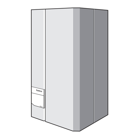
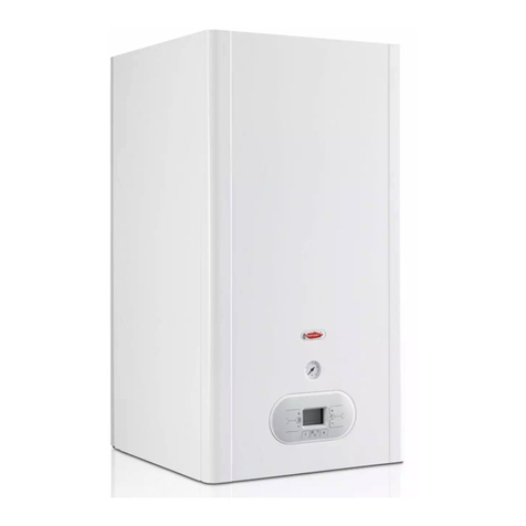
  9. Buderus Logamax plus GB162 Instructions for use

Buderus Logamax plus GB162 Instructions for use

CAUTION!
Before putting the boiler into operation read this manual carefully.
WARNING!
Improper installation, adjustment, alteration, service or maintenance
can cause injury, loss of life or property damage. Refer to this manual.
For assistance or additional information consult a qualied installer,
service agency or the gas supplier.
CAUTION!
The operating manual is part of the documentation that is delivered to
the installation's operator. Go through the information in this manual
with the owner/operator and make sure that he or she is familiar with
all the necessary operating instructions.
NOTICE!
In the Commonwealth of Massachusetts this boiler must be installed
by a licensed Plumber or Gas Fitter.


 


   
_
   
 _

 
   
 
 
 
  
 
 

   
_

Fig. 1 Logamax plus GB162 with pump group
10
17
7
1
32
31
20
27
15
29
5
34 2
8
26
25
9
11
12
13
15
14
22
21
18
19
24
23
28
6
33
3637
3538
16
30
39
42
40
41
34
43

   
 _
 
1: BC10 basic controller receptacle
2: Installation option for room controller, e.g. RC35
3: Cover with user manual compartment
4: BC10 basic controller, can be expanded e.g. by the
RC35 room controller
5: Connection box (low-voltage and 120 VAC
connections)
6: Fan harness and mains lead of the pump
7: Condensate drain outlet
8: Condensate collector
9: Boiler front door
10: Automatic air vent
11: Retaining clips
12: Air intake for the fan
13: Gas pipe
14: Flue gas pipe
15: Door lock
16: Flue measuring point
17: Measuring point for air intake
18: Flue gas connection
19: Air intake connection
20: Fan
21: Gas valve
22: Venturi
23: Burner cover
24: Supply temperature sensor
25: Ionization electrode
26: Sighting glass
27: Glow ignitor
28: Safety temperature sensor
29: Heat exchanger
30: Pressure sensor
31: Return temperature sensor
32: Universal Burner Controller Version 3 (UBA
3
33: Drawer with function module integration o
p
34: Cover shield
35: Condensate trap
Pump group (scope of delivery):
36: Isolating valve, blue (CH boiler return) with pump,
drain cock, check valve and thermometer
37: Manual gas shuto valve, yellow (GAS)
38: Isolating valve, red (CH boiler ow) with drain cock,
pressure gauge, thermometer
39: Pressure gauge
40: Isolating valve
41: Thermometer (optional accessory)
42: Drain valve
43: Safety valve 30 psi (2 bar) (or 50 psi [3.45 bar]
= optional)
The pump group also includes an insulation cover
(see also pump group installation instructions).
Low loss header (scope of delivery, single appliance only):
44: Low loss header (not illustrated)

   
_
 
 
    

   
Pos. Parts Qty Packaging
xob11gnisachtiwrelioB1
1tekcarbllaW2
3 Condensate trap with hose 1
4 Technical documents set 1
5 Supply and return union nuts with
gasket rings
2
6 Screws and plugs for wall bracket 2
7 Union nut for gas connection 1
8 Parallel ue adapter 1
xob11puorgpmuP9
10 Low loss header
(single installation only)
1 1 box
Table 1 Items supplied with GB162-80 kW/100 kW
Fig. 2 Items supplied with unit
0
1
2
3
4
1
2
4
8
3
6
7
5
9
10
   
 _
 
  
Fig. 3 Dimensions and connections without pump group
C
DFE
G
4⅛” (103.5mm)
38.58” (9 80 mm)
5.3” (135 mm)
1/”(35mm)
5/
” (138 mm)
6/” (162 mm)
1½ ” (39mm)
5⅛” (130 mm)
5½”(140 mm)
5⅛” (130 mm)
AB
0020½”(520 mm)
39½”(100 3 mm)
40½” (1030mm)
51⅝” (1310mm)
16” (406 mm)
G
D/F
E
A/B
6”(152 mm)
18⅜” (465 mm) ¼” (6 mm)
20" (500 mm)
20½” (520 mm)
1.2 ” (30mm)
24⅞” (630 mm)
The required permanent clearances (closet) are:
in front: 1” (25 mm)
right side: 0” (0 mm)
left side: 0” (0 mm)
above: 6” (152 mm)
The position selected for installation MUST allow adequate spacefor servicing in
front of the boiler of at least 20” (500 mm).
Maintain an installation clearancefrom combustibleconstruction from hot water
piping of at least 1" (25 mm).
A(LA)=Flue gas connection;
inside diameter 4” (100 mm)
B(AA)=Air intake connection;
inside diameter 4” (100 mm)
C(WB) =Wall Bracket (not shown)
D(VK)=Supply;
G1½’’ union nut with femalethread
E(GAS) =Gas connection to boiler;
Rp1’’ femalethread
F(RK)=Return;
G1½’’ union nut with femalethread
G(AKO)=Condensate outlet;
1¼” (32 mm) O/D


   
_
  
Fig. 4 Dimensions and connections with pump group
G
C
DFE
4⅛” (103.5mm)
38⅝” (9 80 mm)
5⅜
” (135 mm)
1/”
(35 mm)
5/” (138 mm)
6/” (162 mm)
1½ ” (39mm)
5⅛” (130 mm)
5½”(140 mm)
5⅛” (130 mm)
AB
0020½”(520 mm)
39½”(100 3 mm)
40½”(1030mm)
51⅝” (1310mm)
16” (406 mm)
G
D/F
E
A/B
6” (152 mm)
18⅜” (465 mm) ¼” (6 mm)
20" (500 mm)
17” (450 mm)
H/J G
HI
J
1.2 ” (30 mm)
50 /
” (1280mm)
24⅞” (6 30 mm)
The required permanent clearances (closet) are:
in front: 1” (25 mm)
right side: 0” (0 mm)
left side: 0” (0 mm)
above: 6” (152 mm)
The position selected for installation MUST allow adequate space for servicing
in front of the boiler of at least 20” (500 mm).
Maintain an installation clearance from
combustible construction from hot water
piping of at least 1" (25 mm).
1The pump group is an accessory.
A(LA)=Flue gas connection;
inside diameter 4” (100 mm)
B(AA)=Air intake connection;
inside diameter 4” (100 mm)
C(WB) =Wall Bracket (not shown)
D(VK)=Supply;
G1½’’ union nut with femalethread
E(GAS) =Gas connection to boiler;
Rp1’’ femalethread
F(RK)=Return;
G1½’’ union nut with femalethread
G(AKO)=Condensate outlet;
1¼” (32 mm) O/D
H(PF) =Pump group supply;
G1½’’ malethread, at seal
I=Gas connection to pump group;
1” NPT femalethread
J(PR) =Pump group return;
G1½’’ malethread, at seal
   
 _
 
General specications unit GB162-80 (NG) GB162-80 (LP) GB162-100 (NG) GB162-100 (LP)
Gas category Natural gas Propane Natural gas Propane
Rated thermal load btu/h 69,000 - 290,000 58,000 - 270,000
Rated heating capacity,
heating curve 176/140°F(80/60°C)
btu/h
61,400 - 255,200 51,600 - 237,600
Rated heating capacity,
heating curve 122/86°F(50/30°C)
btu/h
68,300 - 281,300
Boiler eciency at max. capacity,
heating curve 176/140°F(80/60°C)
%
8888
Boiler eciency at max. capacity,
heating curve 122/86°F(50/30°C)
%
8979
CSA Output btu/h 261,000 243,000 295,000 279,000
De-ration altitudes 2,000 - 5,500 ft % / 1,000 ft 2.22.32.02.1
De-ration altitudes 5,500 - 8,000 ft % / 1,000 ft 2.02.51.72.1
De-ration altitudes 8,000 - 10,200 ft % / 1,000 ft 2.82.02.61.9
Heating
Maximum ow temperature °F(°C) 190 (88)
Maximum working pressure (boiler) psi (bar) 50 (3.6)
Minimum water circulation volume Gal/h (l/h) 0
Flow temperature °F(°C) 86-190 (30-88), can be set on the BC10 basic controller
Resistance at ΔT = 36°F(20°C) psi (ft.hd) )
(75.4)7.51(62.3
Heating circuit volume of heat exchanger Gal (L) 1.3 (5.0)
Pipe connections boiler, without pump group.
Gas connection in Rp1“
Heating water connection in G1½’’ union nut with female thread enclosed
Condensate connection in (mm) Ø1¼” (32 mm)
Flue gas values
Condensate quantity at 104/86°F
(40/30 °C) Gal/h (L/h) )8.01(58.2)0.9(4.2
pHvalue of condensate pHapprox. 4.1
Flue gas mass ow rate, full load g/s 9.443.53
Flue gas temperature 176/140 °F
(80/60 °C), full load
°F(°C) 153 (67) 149 (65) 169 (76) 165 (63)
Flue gas temperature 176/140 °F
(80/60 °C), partial load
°F(°C) 142 (61) 136 (58) 142 (61) 136 (58)
Flue gas temperature 122/86 °F
(50/30 °C), full load
°F(°C) 118 (48) 114 (46) 124 (51) 120 (49)
Flue gas temperature 122/86 °F
(50/30
°C), partial load
°F(°C) 93 (34) 88 (31) 93 (34) 88 (31)
CO 2content at full load %9.39.69.49,7
Free fan feed pressure Inch w.c.
(Pa) )022(388.0)051(206.0
Flue gas connection
Ø ue gas system, room-air dependent in (mm) Ø 4”(100 mm)
Ø ue gas system, room-air independent in (mm) Ø 4”(100 mm) / 4”(100 mm) parallel
Electrical data
Mains connection voltage VAC, Hz120, 60
Electrical protection rating IPX4D
Fuses Amp 5
Electrical power consumption,
full load (without a pump group)
W
651401
Electrical power consumption,
partial load (without a pump group)
W
9292
Table 2 Technical specications of GB162
61,400 - 293,000 51,600 - 277,200
69,000 - 333,000 58,000 - 315,000
57,400 - 261,900 68,300 - 326,300 57,400 - 308,700
10.54

   
_
The gas orice diameter is marked on the gas orice
(in mm).
Hydraulic resistance of the boiler
Boiler dimensions and weight
Height × width × depth (with pump group) in (mm) 50/ x 20½x 18⅜(1280×520×465)
Weight (without a pump group) lb (kg) 154 (70)
Other specications
Pump group pump UP 26-99
General specications unit GB162-80 (NG) GB162-80 (LP) GB162-100 (NG) GB162-100 (LP)
Table 2 Technical specications of GB162 (continued)
Type of gas
supply Factory pre-setting of the gas control valve
Natural gas Delivered factory-set: Natural Gas
LP-gas Suitable for propane after conversion (also
see the instruction "Conversion to another
type of gas supply").
Information on gas type instruction plate:
Set to gas category: Propane.
Table 3 Factory setting of the gas control valve
Thermal
power
gas boiler
Type of
gas
supply
Altitude
in ft (m)
Gas orice
diameter
in inches (mm)
Venturi
article
number
GB162-
80 kW
Natural
gas
0 - 10,200
(0 - 3,111)
0.331
(8.40) 73983
LPG 0 - 8,000
(0 - 2,440)
0.185
(4.70) 7746900499
LPG 8,000 - 10,200
(2,440 - 3,111)
0.193
(4.90) 7746900499
GB162-
100 kW
Natural
gas
0 - 10,200
(0 - 3,111)
0.331
(8.40) 73983
LPG 0 - 8,000
(0 - 2,440)
0.185
(4.70) 7746900499
LPG 8,000 - 10,200
(2,440 - 3,111)
0.193
(4.90) 7746900499
Table 4 Gas orice diameter
Fig. 5 Boiler resistance curve
7.25
6.5 3
5.80
5.0 8
4.35
3.63
2.90
2.1 8
1.45
0.7 3
2.2 4.4 6.6 8.8 11.0 13
.2 15.4 17.6 19.
822.0
500 1000 1500 2000 2500 3000 3500 4000 4500 5000
500
450
400
350
300
250
200
150
100
50
0
psi mbar
L/h
GPM
100 kW
80 kW
Volume ow
Pressure drop
   
 _

 

   

 
   
 
 
   
 


  
 
  

 
  

 
  

   
   


 
 
    

  


 

   
    

  
Fig. 6 Installing the wall bracket
A
D
C
B
   
  

  

   

Fig. 7 Aligning the boiler with the set screw

   
_
 
 
   
 
  

 
Fig. 8 Overview of cascade frame for Logamax plus GB162-80 kW/100 kW
1: Supports
2: Connecting frame
3: Supply and return header
4: Manual gas shuto valve
5: Mounting bracket
6: Cascade connection set TL-inline
7: Cascade connection set TR-back-to-back
8: Pump group
9: Flange seals - gaskets
10: Low loss header
B2
B1
A1
A1
B1
B2
A2
A2
A1
A2
B1
B2
6
1
4
2
3
910
8
5
7
4
8

   
 _
  


 


 

 




 
 
 
 
 



Fig. 9 Items supplied with the cascade frame
1
2
4
3
  

  






 
  
   

  
 
7DEOH  &DVFDGHVHOHFWLRQ
Appliance
capacity
[kW]
Cascade
system
GB162
80 100
80 Single installation 1 –
100 Single installation – 1
160 TL2, TR2 2 –
180 TL2, TR2 1 1
200 TL2, TR2 – 2
240 TL3, TR3 3 –
260 TL3, TR3 2 1
280 TL3, TR3 1 2
300 TL3, TR3 – 3
340 TL4, TR4 3 1
360 TL4, TR4 2 2
380 TL4, TR4 1 3
400 TL4, TR4 – 4
440 TL5, TR5 3 2
460 TL5, TR5 2 3
480 TL5, TR5 1 4
500 TL5, TR5 – 5
520 TL6, TR6 4 2
540 TL6, TR6 3 3
560 TL6, TR6 2 4
580 TL6, TR6 1 5
600 TL6, TR6 – 6
620 TL7, TR7 4 3
640 TL7, TR7 3 4
660 TL7, TR7 2 5
680 TL7, TR7 1 6
700 TL7, TR7 – 7
720 TL8, TR8 4 4
740 TL8, TR8 3 5
760 TL8, TR8 2 6
780 TL8, TR8 1 7
800 TL8, TR8 – 8

   
 
 
 
Low loss
header
TL- conguration
(inline)
TR- conguration
(back-to-back)
2½" TL2, TL3 not applicable
3" TL4 TR4
eromdnasreliob5"4
Table 6 Low loss header conguration

   
_
 

   
 
Fig. 10 Cascade system conguration varieties
12
12
- Top view -
  
Cascade - step by step
Step 1 Determine the capacity
Determine the capacity required and the number and type of condensing gas boilers
(GB162 - 100 and GB162 - 80).
Step 2 Check the suitability.
Select the optimum cascade installation for the boiler room. Take into consideration any
possible hot water system requirements and the number of heating circuitsto be installed.
Step 3 Check the suitability.
Use the "Hot water step by step" selection tool to select the relevant system.
Step 4 Select the relevant accessories, if any
We supply various accessories for the cascade systems. The controls chapter
describes the accessories which can be used to complete the selected system.
Step 5 Select the controller
Select the controller on the basis of the cascade conguration: e.g. MBC 5 or HW 4121
Step 6 Determine the ue gas system
You can determine the ue system on the basis of the building structure, e.g. using:
– roof terminals;
– prefabricated roof covers;
– collector systems;
– exible stainless steel.
Step 7 Place your order
You can order the cascade conguration from a wholesaler selling N08.4 boilers.
Your order would comprise of the following three components:
– the cascade conguration selected (TL2, TL3 etc.);
– the number of heating boilers (e.g. 1x GB162 - 80, 2x GB162 - 100);
– the number of manifold assemblies required (e.g. 1x manifold assembly heating
system/hot water, 2x manifold assembly pump connection group).
7DEOH&DVFDGHVHOHFWLRQ
   
 _
  
Fig. 11 Dimensions of cascade systems - 1
A: TL - Inline conguration
B: TR - Back-to-back conguration
1: Supply and return header
2: Low loss header
3: Enclosed welding anges
X1 Y1
123
L1
123
1
2
3
4
0
F1
A
B
(525 mm)
20¾”(288 mm)
11¼”
32”(810 mm)
20”(510 mm)
22¾”
(575 mm)
20¾”
(525 mm)
26¾”(1722 mm)
6”(147 mm)
19½” (497 mm)
26½” (675 mm)
D1 D1
- Front view -
- Top view -

   
_

Fig. 12 Dimensions of cascade systems - 2
CAUTION
The dimensional tolerance is ± 5%.
39" (992 mm)
7" (180 mm)
67¼" (1710 mm)
9¾" (247 mm)
3½" (92 mm)
12¼" (310 mm)
- Side view -
Cascade
system
Length Width
X1 + Y1
TL2 43¼"
1100 mm +1½"
38 mm =44¾"
1138 mm
22¾"
575 mm
TL3 64"
1625 mm +1½"
38 mm =65½"
1663 mm
22¾"
575 mm
TL4 84½"
2150 mm +1¾"
42 mm =86¼"
2192 mm
22¾"
575 mm
Table 8 TL-inline congurations
Cascade
system
Length Width
X1 + Y1
TR2 22¾"
575 mm +1½"
38 mm =24¼"
613 mm
39"
992 mm
TR3, TR4 43¼"
1100 mm +1¾"
42 mm =45"
1142 mm
39"
992 mm
Table 9 TR-back-to-back congurations
Cascade system Header diameter D1 (inch) Length L1 (inch) F1 (ange dimension in mm)
TL2, TL3 2½" 19" (482 mm) Blank ange C2631 37.2 NW 65/76.1 PN6
TL4, TR4 3 " 22¾" (571 mm) Blank ange C2631 37,2 NW 80/89 PN6
5 boilers and more 4 " 25½" (651 mm) Blank ange C2631 37.2 NW 100/114¼PN6
Table 10 Header dimensions
   
 _
  
  
Specications TL2 conguration
Capacity in kW 160 180 200
–1208-GB162
21–001-GB162
67 ⅜(1710)inches (mm)thgieH
Length inches (mm)
(incl. straight switch) 64 (1625)
inches (mm)htpeD
Heating water volume ow
in gallons per minute
Max. gas consumption
Possibility of DHW + three-way
valve yes yes no
23 / (595)
31.7 34.8 37.8
702.5 762.5
ft/hr 811.9
7DEOH 7/6SHFL¿FDWLRQV
)LJXUH 7/&RQ¿JXUDWLRQLQFKHV
7⅛
19½
69½
12¼
15 /
20¾
20¾
19½
5⅞
3⅝
9¾
20¾
43⅜
64

   
_
  
 
Specications TL3 conguration
Capacity in kW 240 260 280 300
–12308-
321–001-
thgieH
Length
(incl. straight switch)
htpeD
Heating water volume ow in
gallons per minute
Max. gas consumption ft/hr
Possibility of DHW + three-way
valve
yes yes yes no
GB162
GB162
inches (mm) 67 ⅜(1710)
inches (mm) 84 ⅝(2150)
inches (mm) 23 / (595)
56.8
46.6 50.6 53.7
1051.9 1115.5 1175.5 1239.0
7DEOH 7/6SHFL¿FDWLRQV
64
84⅝
20¾ 20¾ 20¾
19⅝
5⅞
3
⅝
9¾
20¾
7⅛
19½
69½
12¼
15/
)LJXUH  7/&RQ¿JXUDWLRQLQFKHV
   
 _
  
 
Specications TL4 conguration
Capacity in kW 340 360 380 400
–12308-
4321001-
thgieH
Length
(incl. straight switch)
Heating water volume ow in
Max. gas consumption ft/hr
Possibility of DHW + three-way
valve
yes yes yes no
108/ (2765)
1465.0 1507.3 1588.5 1652.0
GB162
GB162
inches (mm)
inches (mm)
inches (mm)
gallons per minute
67⅜(1710)
htpeD23/ (595)
66.4 69.5 72.6 75.7
7DEOH 7/ 6SHFL¿FDWLRQV
)LJXUH 7/ &RQ¿JXUDWLRQ
24¼
84⅝
108/
19⅝
5⅞
7⅛
19½
69½
12¼
15 /
3⅝
9¾
20¾
20¾20¾
20¾
LQFKHV

   
_
  
 
7DEOH  7/6SHFL¿FDW
Specications TL5 conguration
Capacity in kW 440 460 480 500
–12308-
5432001-
thgieH
Length
(incl. straight switch) 132¾ (3370)
htpeD
Heating water volume ow in
Possibility of DHW + three-way
valve
yes yes yes no
GB162
GB162
inches (mm) 67⅜(1710)
inches (mm) 23/ (595)
gallons per minute 85.4 88.4 91.5 94.6
Max. gas consumption ft/hr 1878.0 1941.5 2001.5 2065.1

)LJXUH 7/&RQ¿JXUDWLRQ
7⅛
19½
69½
12¼
15 /
27 /
105⅜
20¾
20¾ 20¾
132¾
5⅞
20¾
3⅝
9¾
20¾
19⅝
LQFKHV

Other manuals for Logamax plus GB162

5

Other Buderus Boiler manuals

Buderus Logano G234X User manual

Buderus

Buderus Logano G234X User manual

Buderus SU120/5 Instruction Manual

Buderus

Buderus SU120/5 Instruction Manual

Buderus Logano plus GB312 Quick guide

Buderus

Buderus Logano plus GB312 Quick guide

Buderus Logano plus GB312 User manual

Buderus

Buderus Logano plus GB312 User manual

Buderus Logano G234X User manual

Buderus

Buderus Logano G234X User manual

Buderus Logano G315 User manual

Buderus

Buderus Logano G315 User manual

Buderus Logano GE515 User manual

Buderus

Buderus Logano GE515 User manual

Buderus Logano G115WS/3 User manual

Buderus

Buderus Logano G115WS/3 User manual

Buderus SU400.5 Manual

Buderus

Buderus SU400.5 Manual

Buderus GB162 User manual

Buderus

Buderus GB162 User manual

Buderus 500-24S User manual

Buderus

Buderus 500-24S User manual

Buderus 500-24S User manual

Buderus

Buderus 500-24S User manual

Buderus G201 User manual

Buderus

Buderus G201 User manual

Buderus SM400/5E User manual

Buderus

Buderus SM400/5E User manual

Buderus Logano GC 144 II User manual

Buderus

Buderus Logano GC 144 II User manual

Buderus Logamax plus User manual

Buderus

Buderus Logamax plus User manual

Buderus Logano G115 WS US/CA User manual

Buderus

Buderus Logano G115 WS US/CA User manual

Buderus GB142 User guide

Buderus

Buderus GB142 User guide

Buderus Logano plus GB312 User manual

Buderus

Buderus Logano plus GB312 User manual

Buderus Logano G515 Quick guide

Buderus

Buderus Logano G515 Quick guide

Buderus Logano GA124 User manual

Buderus

Buderus Logano GA124 User manual

Buderus Logamax plus GB162-100 kW User manual

Buderus

Buderus Logamax plus GB162-100 kW User manual

Buderus Logamax plus GB142-24 User manual

Buderus

Buderus Logamax plus GB142-24 User manual
Buderus Logano G515 User manual

Buderus

Buderus Logano G515 User manual

Popular Boiler manuals by other brands

Laars NTH Installation and operation instructions

Laars

Laars NTH Installation and operation instructions

STIEBEL ELTRON HSBC 300 cool Operation and installation manual

STIEBEL ELTRON

STIEBEL ELTRON HSBC 300 cool Operation and installation manual

Dunkirk 95M-200 quick guide

Dunkirk

Dunkirk 95M-200 quick guide

U.S. Boiler Company MegaSteam MST Installation, operating and service instructions

U.S. Boiler Company

U.S. Boiler Company MegaSteam MST Installation, operating and service instructions

ProTerm RAY 9-24K User and installation instructions

ProTerm

ProTerm RAY 9-24K User and installation instructions

M&G DuraVent DuraStack PRO DCL Installation and maintenance instructions

M&G

M&G DuraVent DuraStack PRO DCL Installation and maintenance instructions

Lochinvar Electric Hot Water and Steam Boilers Operation and maintenance manual

Lochinvar

Lochinvar Electric Hot Water and Steam Boilers Operation and maintenance manual

ECR International PENNCO 15B III Series Installation, operation & maintenance manual

ECR International

ECR International PENNCO 15B III Series Installation, operation & maintenance manual

Ideal Boilers Atlantic 24 Installation & servicing instructions

Ideal Boilers

Ideal Boilers Atlantic 24 Installation & servicing instructions

Williamson-Thermoflo GWC-070 manual

Williamson-Thermoflo

Williamson-Thermoflo GWC-070 manual

Atlantic Boilers MULTI-ELEC STANDARD Series Technical manual

Atlantic Boilers

Atlantic Boilers MULTI-ELEC STANDARD Series Technical manual

Sime MURELLE HE 50 R E instructions

Sime

Sime MURELLE HE 50 R E instructions

Bryan Boilers CLM Specification sheet

Bryan Boilers

Bryan Boilers CLM Specification sheet

Watts AERCO Benchmark 2.0LN Operating & maintenance instructions

Watts

Watts AERCO Benchmark 2.0LN Operating & maintenance instructions

Viadrus OV 100 L Manual for operation and installation

Viadrus

Viadrus OV 100 L Manual for operation and installation

FireBird Envirogreen Combipac HE Technical manual

FireBird

FireBird Envirogreen Combipac HE Technical manual

Immergas EOLO STAR 24 5E instruction manual

Immergas

Immergas EOLO STAR 24 5E instruction manual

Raypak 500 OPERATING AND INSTALLATION Manual

Raypak

Raypak 500 OPERATING AND INSTALLATION Manual

manuals.online logo
manuals.online logoBrands
  • About & Mission
  • Contact us
  • Privacy Policy
  • Terms and Conditions

Copyright 2025 Manuals.Online. All Rights Reserved.