Budmat FWD1 HBM 3x2 Parts list manual

ASSEMBLY AND USAGE INSTRUCTIONS
for Photovoltaic Module
Support Structure
FWD1 HBM
3x2 3x1
INSTRUKCJA MONTAŻU I UŻYTKOWANIA
konstrukcji wsporczej
dla modułów fotowoltaicznych
FWD1 HBM
3x2 3x1
2
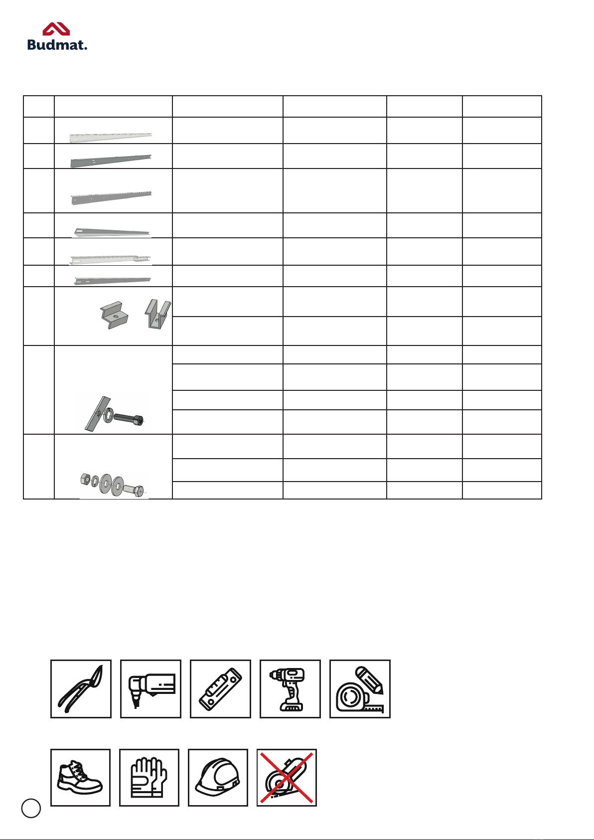
Assembly Kit Components
Tools
OHS
Free-standing structure intended for fastening photovoltaic panels in horizontal orientation,
resting on steel supports driven/concreted into the ground.
The skeleton structure made of steel profiles allows for the assembly of rows
of photovoltaic panels inclined at an angle of 25° to the foundation.
The components are manufactured from S320GD steel with a ZM310/430 MAGNELIS coating.
To join the components, screws of hot-dip galvanized steel (TZn) are used. The structure has
no welded joints, which minimizes the risk of corrosion.
No. Component Name Description 3x2 layout 3x1 layout
1.
Fig. 2.1
FWD1 HBM SP Front post L2420 2 pcs. L2420 1 pcs.
2.
Fig. 2.2
FWD1 HBM ST Rafter L3353 2 pcs. L3353 1 pcs.
3.
Fig. 2.3
FWD1 HBM K Purlin L3615 2 pcs. L3615 1 pcs.
4.
Fig. 2.4
FWD1 HBM T Bracket L2670 2 pcs. L2670 2 pcs.
5.
Fig. 2.5
FWD1 HBM P Splice L3740 4 pcs. L2300 4 pcs.
6.
Fig. 2.6
FWD1 HBM F Inverter mounting L2400 1 pcs.
7.
Fig.2.7/2.8
End clamp 35 8 pcs. 4 pcs.
Mid clamp 8 pcs. 4 pcs.
8.
Fig. 2.9
M8x30 DIN-912 A2-70 8 pcs. 4 pcs.
M8x35 DIN-912 A2-70 8 pcs. 4 pcs.
M8 3mm 16 pcs. 8 pcs.
M8 DIN7980 A2 1.4301 16 pcs. 8 pcs.
9.
Fig. 2.10
M12X30 DIN-934 A2-70 24 pcs. 10 pcs.
M12 DIN-127B A2-70 24 pcs. 10 pcs.
M12 3/13/37 DIN-9021 A2 70 48 pcs. 20 pcs.

3
I.TECHNICAL DOCUMENTATION OF THE COMPANY BUDMAT BOGDAN WIĘCEK
THE MANUFACTURER OF THE STRUCTURE SHALL BE EXEMPTED FROM ANY OBLIGATIONS UNDER THE
WARRANTY UNLESS THE PURCHASER OBSERVES THE GUIDELINES SET FORTH
IN THIS DOCUMENTATION
1. Purpose of the technical documentation
The aim of this technical documentation is to get the Purchaser/User acquainted with the structure, principle
of operation and correct maintenance of the product, as well as to provide guidelines regarding its storage,
assembly and transportation.
2. Packaging, storage and transport
The products should be packed in a manner preventing the loss of any component of the particular system.
After receiving the delivery, please always check the product for its quality and possible lack of components
in the respective kit(s).
Complete assembly systems are delivered to the recipient with protection against damage. The complete-
ness of the delivery as well as appropriate condition of the delivered profiles shall be confirmed in writing by
the recipient on the Stock Issue Confirmation or on any other equivalent document, on which comments
regarding the product, provided there are any, should be written down.
3. Assembly
The assembly is to be conducted in accordance with the instructions issued by Budmat.
Recommended tightening torques during the assembly:
• Mid and end clamps: 10-11 Nm,
(Caution: During the tightening of the screws to the clamps, the rhombic Magnelis nut may become de-
formed at the torque of 11 Nm. This deformation is acceptable.)
• M12 screws and nuts – 79 Nm,
(Caution: Tightening fasteners with impact drivers and/or wrenches is prohibited.)
It is prohibited to interfere with the structure by drilling holes, grinding its edges, cutting it or carrying
out other activities that may damage its protective layer, unless such an activity is admissible as per the
instruction or Budmat consents to such an activity being carried out.
The upper parts of the posts may become deformed while driven into the ground. In that case, the occurring
deformations should be secured with zinc paint along the scratch. Remove any soiling from the components
that has accumulated during the assembly immediately before proceeding to the next assembly phase.
4. Clamp fastening
It is prohibited to use impact drivers with no tightening torque control. With power tools equipped with a
mechanical clutch, the correct tightening torque may, as a rule, not be guaranteed, as it depends on the
state of charge of the battery. In this situation, control the tightening force with a manual torque wrench on
an on-going basis.
BUDMAT BOGDAN WIĘCEK SHALL NOT BE HELD LIABLE FOR DAMAGES AND DEFECTS CAUSED BY
INCORRECT ASSEMBLY. ANY MODIFICATIONS MADE BY THE PURCHASER/USER SHALL RESULT IN THE
WARRANTY BEING INVALIDATED.
5. Product use
a) Maintenance
In order to ensure correct operation and a long useful time of the system, please check the fasteners twice
within the first year of use. In the subsequent years of use, checks should be performed on a regular yearly
basis. Check whether the fastening screws and ordinary screws are tightened and in the correct position. It is
strictly prohibited to step on the structure and to put load on it in any other manner.
Should you notice any of the fastening components loosened, secure the area around the structure against
unauthorised entry and, in compliance with OSH regulations and provisions of the instructions, perform a
repair.

4
b) Cleaning
In order to maintain the attractive appearance of the fastening structure, please clean it regularly. Clean
components of the frame provide for a nicer look, longer durability and better functioning of the structure.
Caution!
Do not use alkaline cleaning agents! The glass on the panels is sensitive to alkaline substances.
System components are best cleaned with water and sponge. However, neutral detergents may also be used.
6. OHS
During the assembly, use and repair of the products covered by this technical documentation, please comply
with generally applicable occupational health and safety regulations. Therefore, you should i. a.:
• Be equipped with personal protective equipment such as helmet and other types of protective gear;
• Use ladders, scaoldings and other lift equipment, whose usability must be duly certified;
• Work with power tools with valid inspection documents. The same rule applies to extension cords
andbranch joints;
• Secure the area in which there is work in progress against unauthorised entry;
• Have a valid medical certificate for work at heights, if necessary.
II. TRANSPORT AND UNLOADING, MAGNELIS COATING
During the assembly, use and repair of the products covered by this technical documentation, please comply
with generally applicable occupational health and safety regulations.
General rules of handling and working with Magnelis-coated profiles
1. For cutting the profiles, use electric sheet metal nibblers, shears, mitre saws etc. It is prohibited to cut the
profiles with an angle grinder. This tool causes the sheets to warm up and results in the Magnelis coating
being damaged (burned out). Chips resulting from the cutting may cause corrosion of the processed
profile and of other profiles in its immediate proximity.
2. If a grinder is used, no claims will be accepted.
3. After each cutting of and drilling of holes into Magnelis-coated profiles, any swarf should be removed
otherwise it may cause corrosion when in contact with the Magnelis-coated profile. Moreover, it poses a
risk to the installer of getting hurt.
4. Any soiling occurring during the assembly works should be removed on an on-going basis.
5. Use protective gloves.
6. In the event of the Magnelis coating being damaged, mask the defects with zinc paint.
7. When working with Magnelis-coated profiles, comply with OHS regulations at all times.
Transport and unloading
1. The profiles should be transported in their original Budmat steel packaging.
2. The vehicle transporting Magnelis-coated profiles should be adapted to this kind of transportation. The
loading, unloading and proper fastening of the goods for the time of transport should be made easy for
the person carrying out these activities.
3. Before unloading, check if the documentation is compatible with the goods delivered. Inspect the deliv
ered goods carefully, and in case of visible defects or incompleteness, describe them in detail in the proto
col or consignment note and have the carrier sign these for confirmation.

5
5 | Strona
UKŁADY STALOWYCH PODPÓR WBIJANYCH / BETONOWANYCH W
PODŁOŻE (SP / ST)
Rys. 1
Rys.
LAYOUTS OF STEEL SUPPORTS DRIVEN/CONCRETED INTO THE GROUND (SP / ST)
Post positioning – Wind rose
N
S
Post
Fig. 1
Fig. 2
3X2 Layout 3X1 Layout
Rear post Rear post
Front post
Front post

6
6 |
Strona
MONTAŻ KROKWI (K)
Rys. 3
Miejsca łączeń krokwi z słupem (elementy łączne tabela punkt 11)
Rys.4
MONTAZ PŁATEW (P)
RAFTER ASSEMBLY (R)
Post positioning – Wind rose
N
S
Post
3X2 Layout 3X1 Layout
Fig. 3
Fig. 4
Rafter-post connection points (Connecting components: Table, no. 11)

7
7 | Strona
Rys. 5
Rys.6
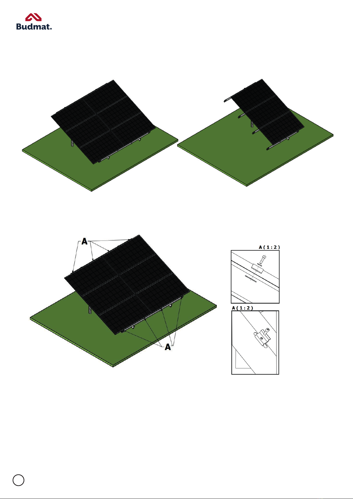
MONTAŻ PANELI FOTOWOLTAICZNYCH
3X2 Layout
3X2 Layout
3X2 Layout
3X1 Layout
Fig. 6
Fig. 5
8
8 | Strona
Rys. 7
A - ŁĄCZENIA KLEM KOŃCOWYCH
Rys. 8
3X2 Layout 3X1 Layout
A – END CLAMP CONNECTIONS
Fig. 7
Fig. 8

9
9 | Strona
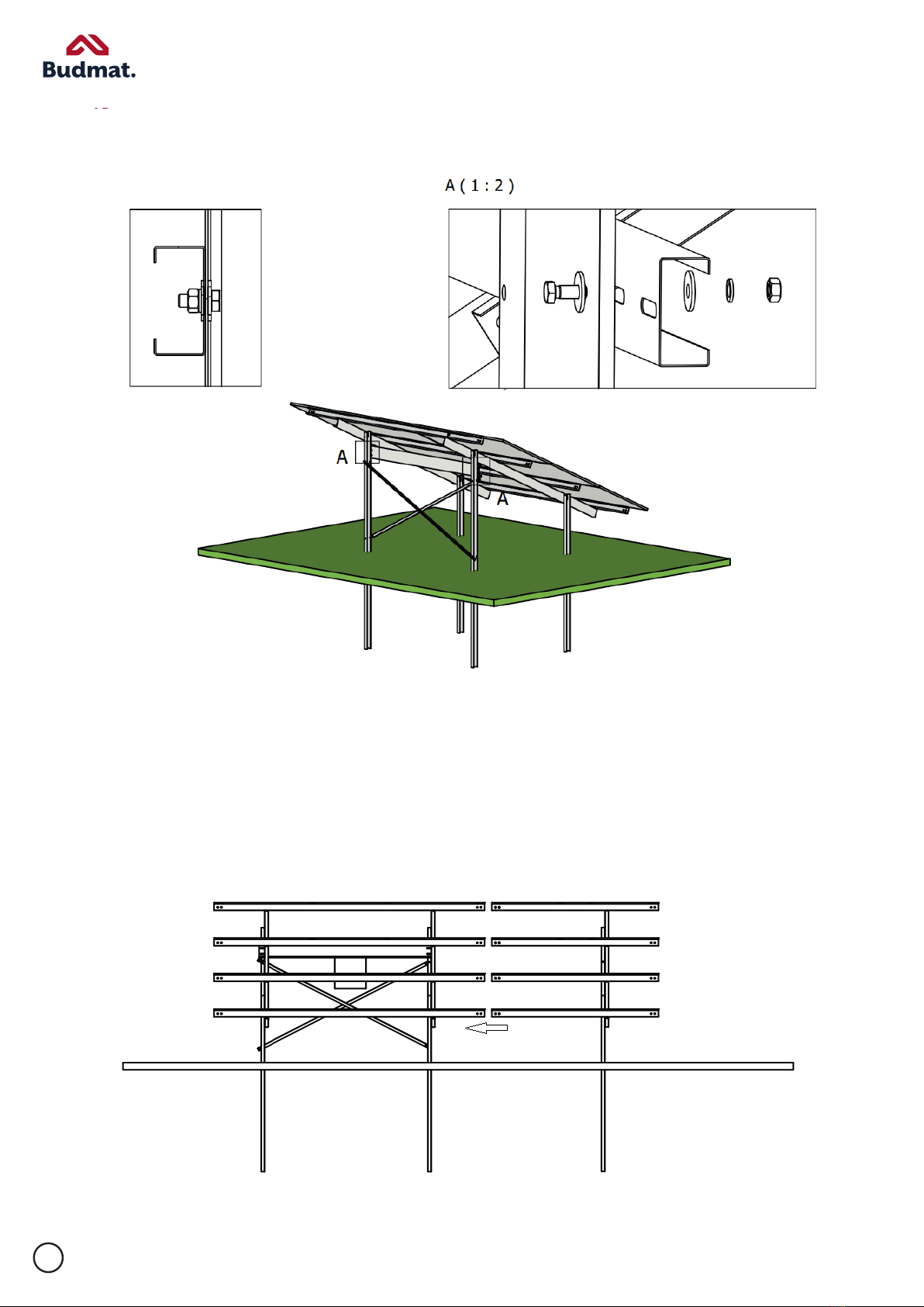
B –ŁĄCZENIA KLEM ŚRODKOWYCH
Rys. 9
MOCOWANIE TĘŻNIKÓW
Rys. 10
MOCOWANIE FALOWNIKA
B – MID CLAMP CONNECTIONS
Fig. 10
Fig. 9
BRACE ASSEMBLY
INVERTER MOUNTING
10
10 | Strona
Rys. 11
ŁĄCZENIE STOŁÓW
Stół 3x2 jest stołem bazowym do niego dołączamy stół 3x1
Fig. 11
TABLE CONNECTION
3x2 Table is the base table. A 3x1 table is connected to it.
This manual suits for next models
1
Table of contents
Other Budmat Solar Panel manuals


