Buehler ISOMET Low Speed Saw Manual

Operation and
Maintenance
Instructions
/SOMETTM
Low
Speed
Saw
©1992 BUEHLER LTD.
Printed in U.S.A.

r
{})ecfaration
of
Conformity
Manufacturer:
Of:
®A
BUEHLER, Ltd.
41
Waukegan Road
Lake Bluff,
Illinois
60044
Declares the following product: /SOMET
n.t
LOW
SPEED
SAW
To be in accordance with
EC
Directive(s);
Safety
of
Machinery: EMC Directive:
89/392/EEC and 91/368/EEC and 93/44/EEC
according to the following standards: 89/336/EEC and 92/231/EEC according to the
following standards:
EN
292 PART 1
1991
EN
292 PART 2
1991
EN
60204 PART 1 1993
Position: Director
of
Engineering
Name: Chuck Motley
Signature:
Cliuc~9rtotfey
EN
50081-1: 1992
EN
50082-1: 1992
Date:
111197
This Manual is a custom generated document. It includes all revisions
relative to this specific Buehleritem
as
of
the date shown below.
MA111280-11 1113/99
I
I
I
I
I
I
I
I
I
I
I
I
I
I
I
I
I
I
I

TABLE OF CONTENTS
DESCRIPTION PAGE
Warranty.......................................................................................................................................2
Unpacking .................................................
..
.................................................................................2
Assembly......................................................................................................................................2
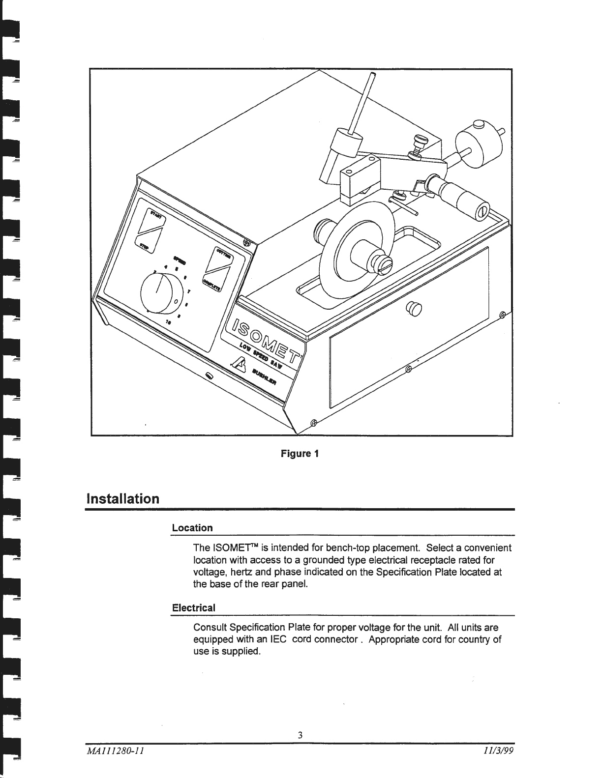
Installation ....................................................................................................................................3
Location....................
..
..............................................................
..
.....................................3
Electrical.......................................
..
...
....
..........................................................................3
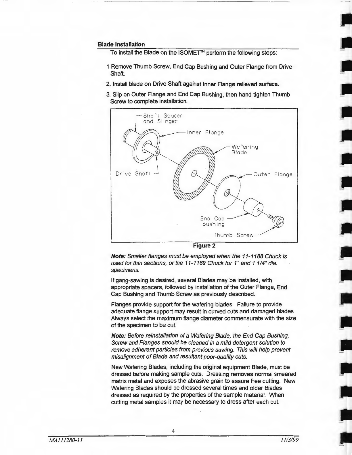
Blade Installation.............................................................................................................4
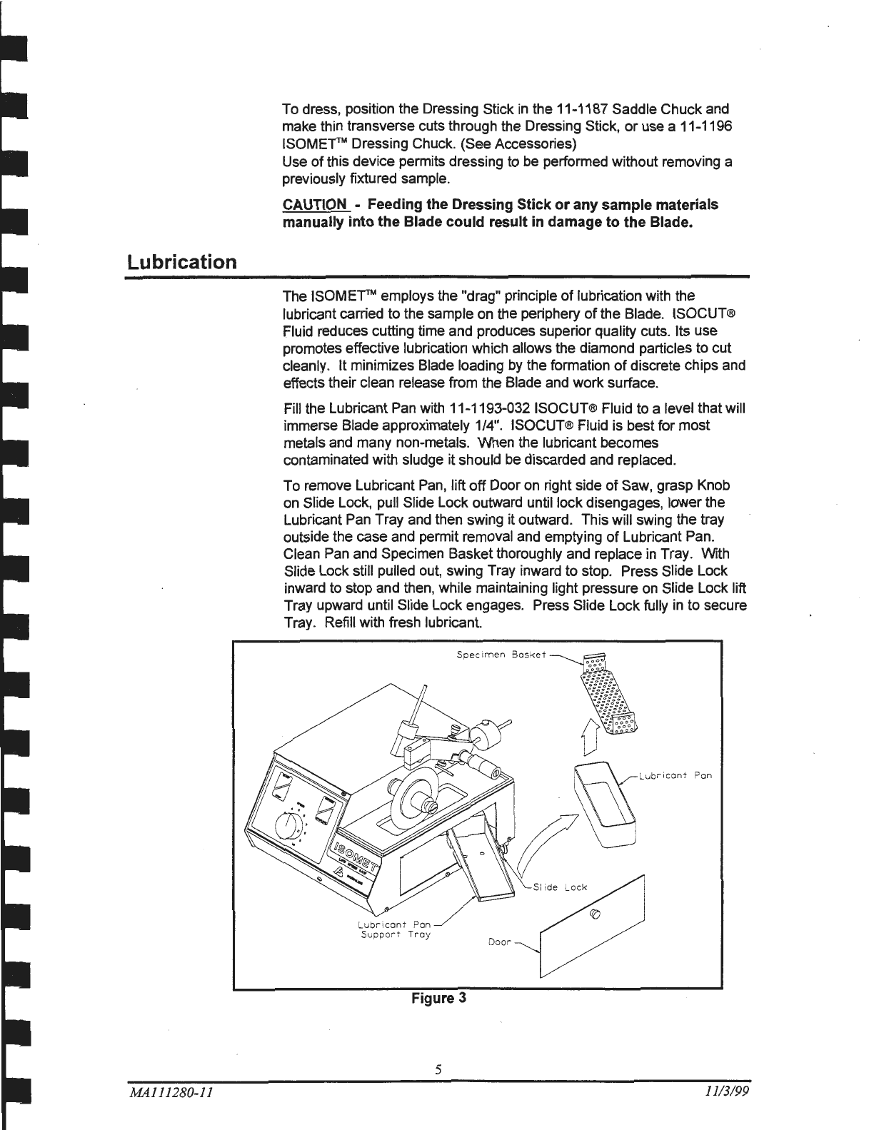
Lubrication
..
...............................................
..
.
..
..............................................................................5
Operation...........................
..
.........................................................................................................6
Loading the Saw..............................................................................................................6
Adjustment
of
Cut-OffSwitch Mechanism.......................................................................6
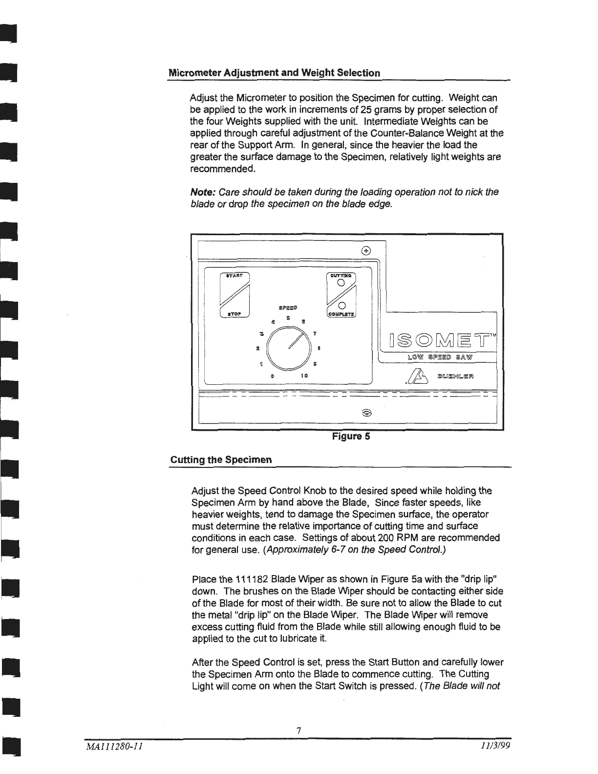
MicrometerAdjustment and Weight Selection ................................................................7
Cutting the Specimen......................................................................................................7
Maintenance...............
..
........................
..
.......................................................................................9
Motor
or
Drive Belt Replacement...........................
..
.......................................................9
Micrometer Screw Adjustment ..................................................................
~
.....................
11
Replacement
or
Exchange
of
Micrometers.....................................................................
11
General Specifications ....................................................
...
..
.......
..
...............
..
.................12
Hot Cell
or
Glove Box Use ...........................................................................................................12
Exploded Assembly Drawings......................................................................................................13
Electrical Connection Drawing ......................................
..
...
.........
..
.
...
...........................................20
Packaging Drawing ..................................................
..
.......................
....
.......................................
21
Parts List ......................................................................................................................................22
Accessories and Supplies.....................................................................................·.......................24
ISOCUT ®Wafering Blades ............................................
..
............................
....
................26
Notes: ....................................................
....
....................
..
.............................................................28
MA111280-11 1113199

-----
--
-
------
--------------
----------------------
----
OPERATION AND MAINTENANCE
INSTRUCTIONS
BUEHLER®
ISOMET™
LOW
SPEED
SAW
Warranty
Unpacking
Assembly
MA111280-11
This unit is guaranteed against defective material and workmanship for a
period
of
two (2) years from the date
of
receipt by customer. Warranty is
void
if
inspection shows evidence
of
abuse, misuse
or
unauthorized
repair. Warranty covers only replacement
of
defective materials.
If,
for
any reason, this unit must be returned to our plant forwarranty service,
please apply for prior authorization with shipping instructions, and include
the following information: Customer Purchase Order Number, Buehler
Ltd. Invoice Numberand Date, Serial Number, and reason for return.
Carefully unpack and check contents.
If
any components are missing
or
damaged, save the packing list and material and advise the carrier and
Buehler®, Ltd.
of
the discrepancy.
The ISOMErrM Low Speed Saw is shipped fully assembled except for a
Diamond Wafering Blade and Dressing Stick which are packed
separately
in
the same box. Three Chucks, Weights, Weight Shaft,
Counter-Balance Weight, Balance Weight Shaft, two (2) Allen Wrenches,
a SpannerWrench, and an optional Chuck mounting screw are packed
separately
in
the Lubricant Pan which is accessible via the dooron the
right panel. (See Accessories)
2
1113/99 I

Installation
MA111280-11
Figure 1
Location
The
ISOME"fTM
is intended for bench-top placement. Select a convenient
location with access to a grounded type electrical receptacle rated for
voltage, hertz and phase indicated on the Specification Plate located at
the base
of
the rear panel.
Electrical
Consult Specification Plate for proper voltage for the unit. All units are
equipped with
an
IEC cord connector . Appropriate cord for country
of
use is supplied.
3
1113/99

MA111280-11
Blade Installation
To install the Blade on the
ISOMETTM
perform the following steps:
1 Remove Thumb Screw, End Cap Bushing and
Outer
Flange from Drive
Shaft.
2. Install blade on Drive Shaft against Inner Flange relieved surface.
3. Slip on Outer Flange and End Cap Bushing, then hand tighten Thumb
Screw to complete installation.
Drive
Sha
ft
Waf e
rin
g
Blade
Outer
Fla
nge
Thumb
Scr
ew
Figure 2
Note: Smallerflanges must
be
employed when the
11
-1188 Chuck is
used for thin sections,
or
the
11
-1189 Chuck
for
1"
and
1
114"
dia.
specimens.
If
gang-sawing is desired, several Blades may be installed, with
appropriate spacers, followed by installation
of
the Outer Flange, End
Cap Bushing and Thumb Screw as previously described.
Flanges provide support for the wafering blades. Failure to provide
adequate flange support may result
in
curved cuts and damaged blades.
Always select the maximum flange diametercommensurate with the size
of
the specimen to be cut.
Note: Before reinstallation
of
a Wafering Blade, the End Cap Bushing,
Screw and Flanges shouldbe cleaned in a mild detergent solution to
remove adherentparticles from previous sawing. This will help prevent
misalignment
of
Blade and resultantpoor-quality cuts.
New Wafering Blades, including the original equipment Blade, must be
dressed before making sample cuts. Dressing removes normal smeared
matrix metal and exposes the abrasive grain to assure free cutting. New
Wafering Blades should be dressed several times and older Blades
dressed as required by the properties
of
the sample material. When
cutting metal samples it may be necessary to dress after each cut.
4
11
/3/99

Lubrication
MA111280-11
To dress, position the Dressing Stick
in
the 11-1187 Saddle Chuck and
make thin transverse cuts through the Dressing Stick,
or
use a 11-1196
ISOMETTM
Dressing Chuck. (See Accessories)
Use
of
this device permits dressing to be performed without removing a
previously fixtured sample.
CAUTION -Feeding the Dressing Stick
or
any sample materials
manually into the Blade could result in damage to
the
Blade.
The
ISOMETTM
employs the "drag" principle
of
lubrication with the
lubricant carried to the sample on the periphery
of
the Blade. ISOCUT®
Fluid reduces cutting time and produces superior quality cuts. Its use
promotes effective lubrication which allows the diamond particles to cut
clean
ly.
It
minimizes Blade loading by the formation
of
discrete chips and
effects their clean release from the Blade and work surface.
Fill the Lubricant Pan with 11-1193-032 ISOCUT® Fluid to a level that will
immerse Blade approximately 1/4". ISOCUT® Fluid is best for most
metals and many non-metals. When the lubricant becomes
contaminated with sludge it should be discarded and replaced.
To remove Lubricant Pan, lift
off
Door on right side
of
Saw, grasp Knob
on
Slide Lock, pull Slide Lock outward until lock disengages, lowerthe
Lubricant Pan Tray and then swing it outward. This will swing the tray
outside the case and permit removal and emptying
of
Lubricant Pan.
Clean Pan and Specimen Basket thoroughly and replace
in
Tray. With
Slide Lock still pulled out, swing Tray inward to stop. Press Slide Lock
inward to stop and then, while maintaining light pressure on Slide Lock lift
Tray upward until Slide Lock engages. Press Slide Lock tully
in
to secure
Tray. Refill with fresh lubricant.
D
oor
Figure 3
5
11
/3/99

Operation
Loading the
Saw
Loosen the Set Knob and slip the Counter Balance Weight to the rear
of
the Counter Balance Weight Shaft to hold the Support arm in an upright
position. Select the proper Chuck for the particular application and clamp
the Specimen in place.
It
may be necessary to sandwich strips
of
metal
between the Specimen and Chuck,
or
to improvise
in
other ways
in
order
to clamp certain odd
or
irregular shaped samples. Attach the loaded
Chuck to the Support arm with the Chuck Mounting Thumb Screw
(If
a
larger Chuck is being used
or
a heavyspecimen is being supported in the
Chuck the optional SocketHead Cap Screwcan be used to mountthe
Chuck using the supplied Wrench). After the Chuck is secured, move the
Support arm to the far left by adjusting the Micrometer Head. Slide the
Counter-Balance Weight toward the front
of
the unit until balance is
achieved and tighten the Set Knob.
Weight
Shaft
150g
Weight
.J
~
25g Weight
75g
Weight____>--J
~
50g
Weight__;>-..}
Cut-Off
Switch
Adjusting
Thumb
Screw
Counterbalanc
Weight
Shaft
humb
Screw
for~
Counterbalance
Weight
Chuck
Mounting
MA111280-11
Support
Mi
crometer
Cut
-
Off
Switch
Arm
Adjustment
of
Cut-Off Switch Mechanism
Set the Thumb Screw
in
the SupportArm to shut offthe Saw by
depressing the Cut-Off Switch Arm, either at the completion
of
the cut
or
just
before completion. The latter setting allows a weight reduction
before the cut is completed and thereby prevents possible burring
or
cleaving
of
fragile materials near the end
of
the cut.
6
11/3/99
I
I
I
I
I
I
I
I
I
I
I
I
I
I
I
I
I
I
I

MA111280-11
Micrometer Adjustment and Weight Selection
Adjust the Micrometer to position the Specimen for cutting. Weight can
be applied to the work
in
increments
of
25 grams by proper selection
of
the fourWeights supplied with the unit. Intermediate Weights can be
applied through careful adjustment
of
the Counter-Balance Weight
at
the
rear
of
the SupportArm.
In
general, since the heavier the load the
greater the surface damage to the Specimen, relatively light weights are
recommended.
Note: Care should
be
taken during the loading operation
not
to nick the
blade
or
drop the specimen on the blade edge.
®
[;1
[Y
~
II!L"Il!lm
~
5
dil
I
·:0:·
D~@~~UTM
&.©W
!;Iii"~~@
@fA
W
.~I:Jil.Jlll!:IXJIL.Il!llll
0
10
@
.
F1gure
5
Cutting the Specimen
Adjust the Speed Control Knob to the desired speed while holding the
Specimen Arm by hand above the Blade, Since faster speeds, like
heavierweights, tend to damage the Specimen surface, the operator
mustdetermine the relative importance
of
cutting time and surface
conditions
in
each case. Settings
of
about 200 RPM are recommended
for general use. (Approximately 6-7 on the Speed Control.)
Place the 111182 Blade Wiper as shown
in
Figure
Sa
with the "drip lip"
down. The brushes on the Blade Wiper should be contacting either side
of
the Blade for most
of
their width. Be sure not to allow the Blade to cut
the metal "drip lip" on the Blade Wiper. The Blade Wiperwill remove
excess cutting fluid from the Blade while still allowing enough fluid to be
applied to the
cut
to lubricate it.
After the Speed Control is set, press the Start Button and carefully lower
the Specimen Arm onto the Blade to commence cutting. The Cutting
Light will come on when the Start Switch is pressed. (The Blade will not
7
11/3/99

•
MAl11280-11
startturning until the Speed Control Knob is
set
above the Zero setting.)
When the
cut
is completed, the Cut-OffSwitch
Arm
is automatically
depressed which, in turn, lights the Complete Light and stops the Saw.
The Power Switch on the back
of
the
ISOMEf'TM
is also a 2 pole circuit
breaker providing protection for the unit
in
the event
of
overload.
Continual tripping
of
the circuit breaker indicates that a problem exists
within the unit.
Figure
Sa
8
111182
Blade
Wiper
1113199
I
I
I
I
I
I
I
I
I
I
I
I
I
I
I
I
I
I

Maintenance
CAUTION-
DO NOT PERFORM ANY REPAIRS
OR
ADJUSTMENTS FOR A
PERIOD OF
TWO
(2) YEARS. WARRANTY IS
VOID
IF INSPECTION
SHOWS EVIDENCE OF ABUSE OR UNAUTHORIZED REPAIR.
The
ISOMETTM
Saw
is designed and builtto require very little service.
The sealed ball bearings
of
the Drive Shaft and Micrometer Shaft and the
sealed continuous duty Motor require no lubrication.
If
Maintenance is required, first disconnect unit from electrical
powersource.
Motor
or
Drive Belt Replacement
MA111280-11
Spacer
To
replace the Motor (1280S195)
or
Drive Belt (R10066) the Front and
Back Panels
of
the ISOMETN need to be removed. Remove the two
Screws (3000S104) holding the Front Panel and push the Panel outward
from inside the Lubricant Tray compartment. Disconnect the Electrical
Plug from the socket and remove Panel. Remove the three small screws
(1180S68) holding the Back Panel and push the Panel outward.
Motor
Power
Drive
Motor
Base
Plate
Figure 6
1.
To remove the Motor, disconnect the 2 leads from the Motor Control
Board and the single ground wire from the Base Plate. Unscrew the four
Hex Head Screws (R2405)
on
the underside
of
the Base Plate.
9
11/3/99

MA111280-11
2.
To
replace the Belt, loop the new Belt overthe Drive Shaft Pulley
(1180S60) and then slip onto the larger Pulley (1280S196). Care should
be taken notto stretch the Belt excessively upon installation.
(See Figure 7).
Pulley
Figure 7
10
Dr
i
ve
Belt
Or
ive
Shaft
Pulley
11/3/99
I
I
I
I
I
I
I
I
I
I
I
I

MA111280-ll
Micrometer Screw Adjustment
To
clean
or
adjust the MicrometerScrew Assembly, perform the following
steps:
1.
Remove the End Screw with a thin blade screwdriver.
2. Loosen the Thimble by tapping against the end
of
the Thimble with a
plastic hammer
or
screwdriver handle.
3. Carefully remove the Thimble from the Shaft.
4. Clean the exposed assembly with a grease solvent to remove gummy
residues and contaminant particles.
5.
To
adjust Micrometer Screw Drag attach the provided Spanner
Wrench to the hole
in
the Adjusting Nut. Turn counterclockwise to
loosen, clockwise to tighten the drag.
6. Lubricate the assembly with #1620 StarrettTool and Instrument Oil
or
equivalent.
7.
Reinstall by first lining up the 0 line on the Thimble with the graduated
index line
on
the Sleeve.
8.
Tighten the End Screw while holding the Thimble
in
place.
Replacement
or
Exchange
of
Micrometers
It
is necessary to remove the exterior case
of
the
ISOMETTM
to replace
the Micrometer
or
interchange English and Metric Scale Micrometers.
The following procedure should be used:
1.
Unplug unit from electrical power source.
2. Remove Shaft Thumb Screw, End Cap Bushing, Flanges, Blade and
Spacer.
3.
Remove Arm Assembly by removing two (2) Screws that hold Clamp
to Arm.
4. Remove MicrometerThimble by following steps 1-3 under Micrometer
Screw Adjustment.
5.
Remove Lubricant Pan with Basket by swinging out Support Tray.
6. Remove six Screws (three on each side) attaching Case to Base
Plate.
7.
Remove two Front Screws, pull
off
Front Panel and disconnect
Electrical Plug.
8.
Pull Rear Panel backward after removing the three Rear Screws. The
Rear Panel should not be completely detached from the unit
(wires should remain connected) but can be pulled far enough back to
allow the Case to clear.
9.
Tip the case toward the Shaft side and slide over Shaft, Micrometer
Spindle, and Cut-Off Switch Arm.
Reassemble
in
reverse sequence taking care not to pinch electrical wires
or
bend the Micrometer Spindle, the Cut-Off Switch Arm,
or
the precision
Blade Shaft.
II
1113/99

General Specifications:
1.
Tested sound level pressure less than 70 db.
Hot Cell or Glove Box Use
MAl
11280-11
When the
ISOMETTM
is used in a Hot Cell
or
Glove Box, the inert
atmosphere may cause excessive motor brush wear. Brushes may need
to be replaced as often as once a month. Such replacement is not
covered by the Warranty
12
1113199
I
I
I
I
I
I
I
I
I
I
I
I
I
I
I
I
I
I
I

SEE DETAIL E
SEE DETAIL F
SEE DETAIL B
lsomet™ Low Speed Saw UnitAssembly
13
MA111280-11 1113199

1180S68
R4559
{2)
{SEE NOTE
1)
1280S181
NOTES :
1280S195
R7850
{3)
11
DO
NOT COMPLETELY TIGHTEN BOTTOM SCREW
SECURING RELAY
TO
WALL.
THERE SHOULD
BE
SUFFICIENT CLEARANCE
FOR
RELAY
TO
SLIDE
OUT
OF
BOTTOM SCREW WI
TH
LITTLE
OR
NO
RESISTANCE.
R10066
2)
THE MOLEX PIN (
R7036}
ON
THE
SWITCH WIRE
LABELED
5 CONNECTS
IN
TO
THE
EMPTY SOCKET
IN
THE
MALE MOLEX CONNECTOR
IN
THE
WIRE
HARNESS .
R0612LW
1180
S30
{REF
I
OUT)
{21
-DETAIL
A-
MAIN
ASSEMBLY
lsomet™
Low
Speed
Saw
Unit
Assembly
14
MA111280-11
I
I
I
I
I
I
I
I
I
I
I
I
I
I
I
I
I
I
11/3199 I

R8624
(4)
1280S174
R9835
MA111280-11
1280S180
-DETAIL
B-
BACK
PAN
EL
ASS
E
MBLY
1280S178
1280S176
lsometTM
Low Speed Saw Unit Assembly
15
R9700
APPLY
R7713
VAC
UUM
GREASE
-DETAIL
C-
suPPORT
TRAY
ASS
E
MBLY
MOUNTING
1113/99

(PART
OF
WIRE
R9354
(SEE NOTE 1J
R0585
(2 1
(SEE NOTE 2 1
CONNECTOR
FROM
WIRE
31
-DETAIL
Dl
-
LAMP
MO
UN
TING
I
J
R9351
(115VJ
R9352
1250V
J
(SEE
DETAIL
D 1I
1280S
1
68
~R
8370
A
1180S72
1280S
169
I
REF
I
1
280S
173
R9349
(1
1
5V)
R9350
(
250V
I
ISEE
DETAIL
D 1J
1280S167
(PART
OF
WIRE HARNESS J
(1
280S175
REF
)
-DETAIL
D-
FRONT PAN
EL
ASSEMBLY
NOTES :
I)
W
HE
N MOUNTING KNOB
IR9354
) ONTO SWITCH
POT
I 1
280S
1751 TURN SWITCH POT COUNTER -
CLOCKWISE TO STOP. THEN
ALIG
N KNOB
TO
0 (ZERO )
ON
PANEL.
TIGHTEN KNOB SET SCREW
TO
LOCK KNOB
IN
PLACE.
2)
USE
R0585
TIE WRAP AROUND MIDPOINT
OF
LAMP TO SECURE
WIRE
LEADS
TO
PREVENT
WIRES FROM TOUCHING
BELT
AND PULLEY
(BOTH
LAMPS
I
lsomet™
Low
Speed
Saw
Unit
Assembly
16
MA111280-ll 11/3/99
I
I
I
I
I
I
I
I
I
I
I
I
I

1180568
(61
NOTESo
12805179
SEE DETAIL A
SEE DETAIL D
I
SEE
CAL IBRATION PROCEDURE DOCUMENT N
UMBER
610W0020
FOR
POT ADJUSTMENT
ON
MOTOR CONTROL
BOARD
SEE DETAIL B
THE
MICROMETER
THIMBLE
WILL
HAVE
TO
BE
REMOVED
TO
MOUNT
THE
CASE
II
80S
I
-DETAIL
E-
FRONT
PANEL.
REAR
PANEL
AND
CAB
INET MOUNTING
lsometTM
Low
Speed
Saw
Unit
Assembly
17
MA111280-11 11/3/99

I
I
i
I
I
I
SEE
DETAIL
E l
6.
NO
TES:
R6116
(TRIM
TO
APPROX . SHAPE
AND PLACE UNDER ARM)
-~,~"""
L228,,,
I } 11
80S
129
AND
I I
80S
123
ARE
WRAPPED
IN
MICROFOAM
AND
PLACED UNDER TANK SU
PPORT
TRAY
I1280S176}
AFTER TRAY IS LOCKED
IN
UP POSITION
2}
1180S52
SLINGER FITS ONTO
GROOVE
IN
I 1
80S51
SHAFT SPACER .
1180S129
I
SEE
NOTE 1l
1)
1
180S4
I
REF
l
1180S3
-DETAIL
F-
ARM
AND FLAN
GE
MOU
NT
IN
G
lsometTM
Low
Speed
Saw
Unit
Assembly
18
MAl
11280-11
I
I
I
I
I
I
I
I
I
I
I
I
I
I
I
I
I
I
1113/99
I
This manual suits for next models
1
Table of contents
Other Buehler Saw manuals
Popular Saw manuals by other brands

King Canada
King Canada KC-10MB instruction manual

Slugger
Slugger Metal Cutter MCSL07 Operator's manual

EINHELL
EINHELL TH-MS 2513 L Original operating instructions

RotoZip
RotoZip DM10 Operating/safety instructions

Central Machinery
Central Machinery 63469 Owner's manual & safety instructions

Gude
Gude GFO 1801 Translation of original operating instructions

Trajan
Trajan 125 Instructions for use and maintenance / spare parts

NORDFOREST
NORDFOREST 46-217 operating manual

DeWalt
DeWalt DWM120 Original instructions

Makita
Makita 5604R instruction manual

MEAT GEAR
MEAT GEAR SIE360AIHER3HP1P Instructions for Operation, Service and Maintenance

Makita
Makita MLS100 instruction manual