Bulldog Scrubbers SS20 User manual

User Manual
Walk-Behind Scrubber
Traction Drive Cylindrical Deck
www.bulldogscrubbers.com
877-292-3935
SS20
Factory Cleaning Equipment, Inc.
800-793-3790
www.thesweeper.com

2
This manual is furnished with each new Floor Scrubber. This provides the necessary operating and preventive
maintenance instructions. Operators must read and understand this manual before operating or servicing this machine.
This machine was designed to give you excellent performance and efficiency. For best results and minimal cost, please
follow the general guidelines below:
·Operate the machine with reasonable care.
·Follow the manufacturer’s suggested maintenance instructions as provided in this booklet.
·Use original Manufacturer supplied parts.
Technical Specifications
Model Floor Scrubber Traction Drive Cylindrical
Model No. SS20
40 amps
140Ah @20 hr
100Ah @20 hr
69 dBA
20 in (51 cm)
34 in (86 cm)
27,280 ft2 /hr ( 2,534 m2)
3.1 mph (5 km/hr)
3 mph (4.8 km/hr)
24 volts
65 cfm (110 m3/hr)
45 inches ( 112mbar)
.60 HP (450 W)
Cylindrical
3/4 HP (550W)
2
600 RPM
12Gal (45 liters)
13 Gal (49 liters)
2%
370lbs (168 kg)
235 lbs (107 kg)
44.5 x 24.0 x 38.0 (112.8 x 47.8 x 107.4 cm)
1/5 HP (150W)
Current (Max)
Battery Capacity (Lead Acid)
Battery Capacity (Gel)
Sound Level
Cleaning path width
Squeegee width
Productivity
Working speed
Transport Speed
Rated voltage
Vacuum flow
Vacuum water lift
Vacuum power
Brush type
Brush motor(s) power
Number of brushes
Brush RPM
Solution capacity
Recovery capacity
Working Grade
Weight with batteries
Weight without batteries
Dimensions (LxWxH)
Drive Motor Power
Factory Cleaning Equipment, Inc.
800-793-3790
www.thesweeper.com

3
Safety Instructions...................................................................................................................4
IMPORTANT SAFETY INSTRUCTIONS................................................................................4
FOR SAFETY DURING OPERATION....................................................................................4
FOR SAFETY WHEN SERVICING or MAINTAINING MACHINE 4
Unpacking Instructions ...........................................................................................................4
Inspection...............................................................................................................................4
Electrical.................................................................................................................................4
Batteries.................................................................................................................................4
Operator Responsibility..........................................................................................................4
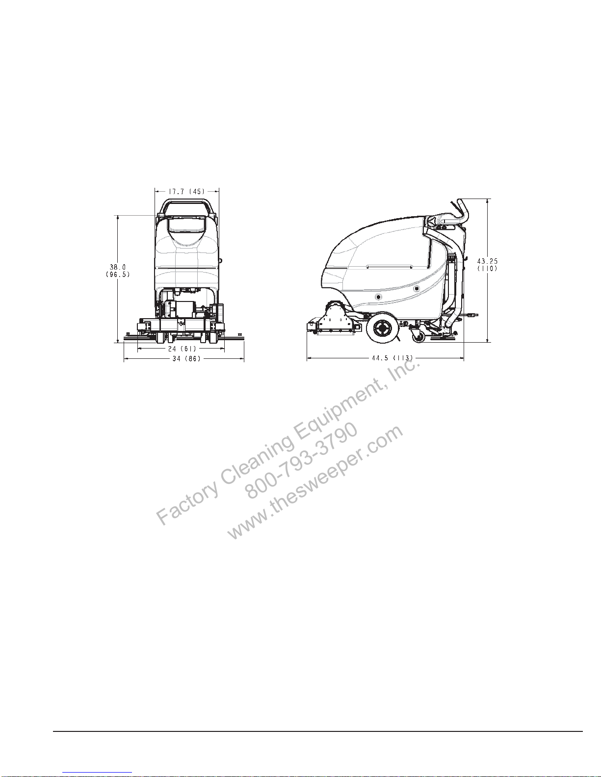
Machine Overview....................................................................................................................5
Machine Overview - Front......................................................................................................5
Machine Overview - Rear.......................................................................................................5
Controls .................................................................................................................................6
Bail Handle.........................................................................................................................6
Handle Adjustment Knobs..................................................................................................6
Key Switch..........................................................................................................................6
Direction Switch..................................................................................................................6
Squeegee Lift Lever...........................................................................................................6
Battery / Fault Gauge.........................................................................................................6
Speed Control ....................................................................................................................6
Charge Status Indicator......................................................................................................6
Optional Hour Meter...............................................................................................................7
Circuit Breakers......................................................................................................................7
Battery Compartment.............................................................................................................7
Diagnostic Code Guide ..........................................................................................................8
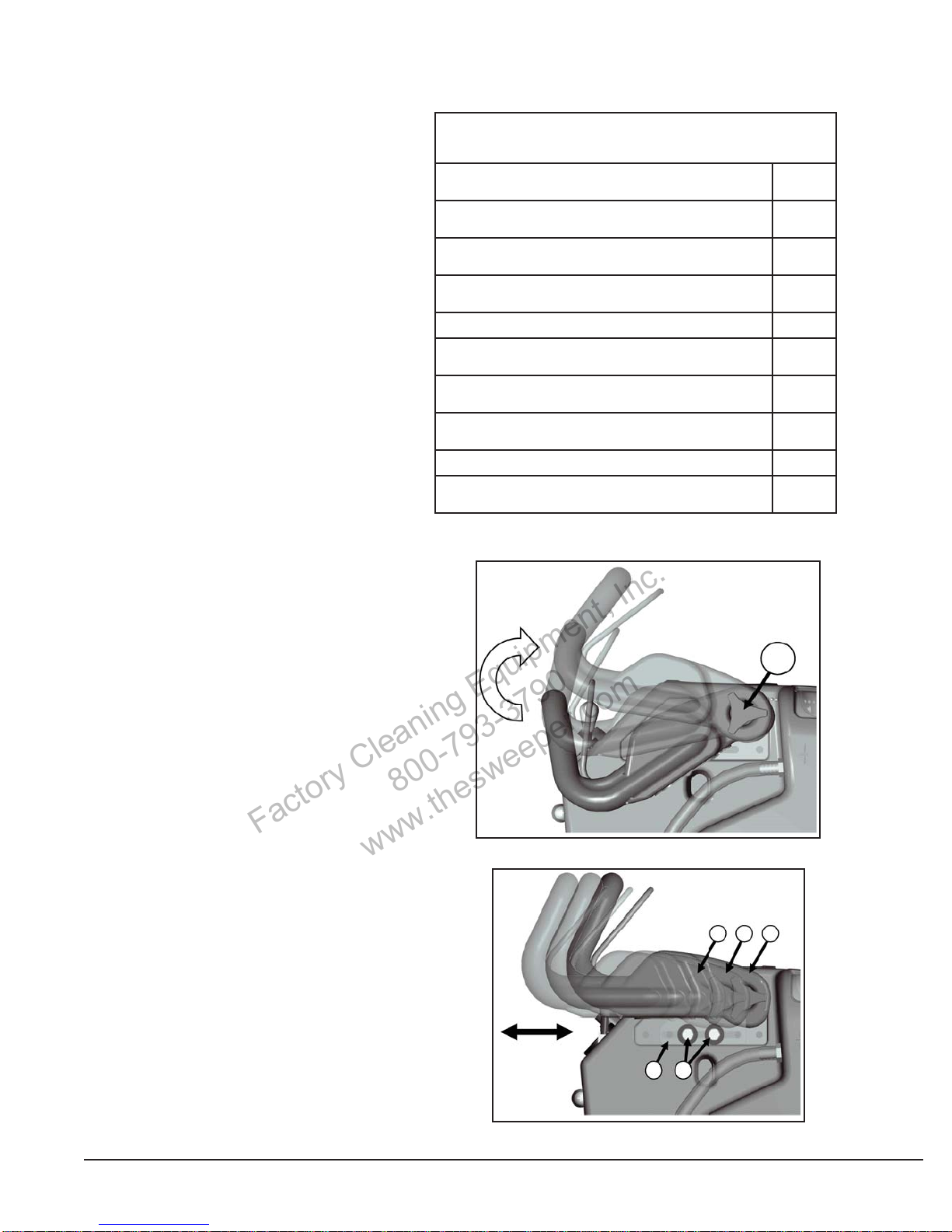
Handle Adjustment.................................................................................................................8
Angle Adjustment ...............................................................................................................8
Horizontal Adjustment ........................................................................................................8
Solution Tank Drain Hose.......................................................................................................9
Solution Level Indicator..........................................................................................................9
Solution Fill Filter....................................................................................................................9
Screened Float.....................................................................................................................10
Screened Float Removal..................................................................................................10
In-Line Solution Filter Assembly...........................................................................................11
Rear Squeegee ...................................................................................................................11
Cleaning the Squeegee....................................................................................................11
Changing the Squeegee Blades.......................................................................................11
Squeegee Blades ............................................................................................................12
Angle Adjustment ............................................................................................................12
Squeegee Blades ............................................................................................................12
Height Adjustment ...........................................................................................................12
Brush Deck Maintenance.....................................................................................................12
Brush Loading / Unloading ..................................................................................................13
Brush Deck Maintenance.....................................................................................................13
The Floor Scrubber Cylindrical.............................................................................................14
Machine Operation.................................................................................................................15
To Turn ON Machine: ...........................................................................................................15
To Turn ON Vacuum:............................................................................................................15
To Turn ON Brush Motor: .....................................................................................................15
To Turn on Cleaning Solution:..............................................................................................15
Direction Switch:...................................................................................................................15
Speed control:......................................................................................................................15
Driving:.................................................................................................................................15
To Charge Batteries:.............................................................................................................15
Hour Meter (Optional):..........................................................................................................15
After Use .................................................................................................................................15
Maintenance............................................................................................................................16
Troubleshooting.......................................................................................................................17
Table Of Contents
Factory Cleaning Equipment, Inc.
800-793-3790
www.thesweeper.com

4
Safety Instructions
IMPORTANT SAFETY INSTRUCTIONS
Operators must read and understand this manual before operating or maintaining this machine.
Do not operate this machine in flammable or explosive areas.
Thismachineisdesignedsolelyforscrubbingdirtanddustinanindoorenvironment.TheManufacturerdoesnotrecommend
using this machine in any other capacity.
The following information below may cause a potential hazard to the operator and equipment. Read this manual carefully
and be aware when these conditions can exist. Take necessary steps to locate all safety devices on the machine and train
the personnel operating the machine. Report any machine damage or faulty operation immediately. Do not use machine
if it is not in proper operating condition.
FOR SAFETY DURING OPERATION
Keep hands and feet clear of moving parts while machine is in operation.
Make sure all safety devices are in place and operate properly.All covers, doors and latches must be closed and fastened
before use.
During operation, attention should be paid to other persons in the work area and especially if small children are present.
Electric motors and components can cause an explosion when operated near explosive materials or vapor. Do not operate
this machine near flammable materials such as solvents, thinners, fuels, grain dust, etc.
Store or park this machine on a level surface only. To prevent unauthorized use, machine should be stored or parked with
the key removed.
This machine is designed for level operation only. Do not operate on ramps or inclines greater than 2%.
This machine is not suitable for picking up hazardous dusts.
Use caution when moving this machine into areas that are below freezing temperatures. Any water in the tanks or hoses
can cause damage to the machine.
FOR SAFETY WHEN SERVICING or MAINTAINING MACHINE
Stop on level surface.
Disconnect the power to the machine by unplugging the red Battery connector located under the recovery tank near the
batteries.
Avoid moving parts. Do not wear loose jackets, shirts, or sleeves when working on machine.
Avoid contact with battery acid. Battery acid can cause burns. When working on or around batteries, wear protective
clothing and safety glasses. Remove metal jewelry. Do not lay tools or metal objects on top of batteries.
Charging batteries generates explosive gasses.
Do not charge batteries when open flames or sparks are present. Do not smoke.
Make sure the charger is turned off before disconnecting it from the machine.
Charge the batteries in a well-ventilated area with the battery cover removed completely.
Do not clean machine with a pressure washer.
Authorized personnel must perform repairs and maintenance. Use Manufacturer supplied replacement parts.
SAVE THESE INSTRUCTIONS
Unpacking Instructions
Inspection
Carefully unpack and inspect your Walk-Behind Scrubber for shipping damage. Follow unpacking instructions on
shippingpallet.Each unithasbeentestedand thoroughlyinspectedbefore shipment.Any damage isthe responsibility
of the delivery carrier who should be notified immediately.
Electrical
This machine is battery operated and designed to operate on 24 volts DC (2) 12-volt batteries.
Batteries
The recommended batteries are rated 140Ah WET (Manufacturer’s P/N 956140) or 100Ah MAINTENANCE FREE
GEL (Manufacturer’s P/N 956100). We do not recommend mixingAMP hour capacities.Alternate battery sets can
be used if they equal physical size and capacity. If alternate battery sets are used please contact the manufacturer
for on board charger settings.
Operator Responsibility
Read this manual carefully before operating this machine.
The operator is responsible for taking care of the daily maintenance and check ups of the machine to keep it
in good working condition. The operator must inform the service mechanic or supervisor when the scheduled
maintenance intervals are required as stated in the MAINTENANCE section of this manual.
Before starting familiarize yourself with the machine and its controls (see “Machine Overview, Front”, “Machine
Overview, Rear”, “Control Console” diagrams).
Factory Cleaning Equipment, Inc.
800-793-3790
www.thesweeper.com

5
Machine Overview
Machine Overview - Front
A CUP HOLDER
B SOLUTION FILL PORT
C RECOVERY TANK LID
D RECOVERY TANK
E BRUSH DECK
F FRONT WHEEL (see note)
G REAR CASTER
H SOLUTION TANK
* NOTE - Front tires are foam filled to
be maintenance-free. No air can be
added.
Machine Overview - Rear
A BAIL HANDLE
B SQUEEGEE LIFT LEVER
C RECOVERY TANK DRAIN HOSE
D ONBOARD CHARGER CORD
E CIRCUIT BREAKERS
F RECOVERY HOSE
G CONTROL PANEL
H SOLUTION TANK DRAIN HOSE / LEVEL INDICATOR
I BRUSH LIFT PEDAL
J REAR SQUEEGEE
K DIAGNOSTIC CODE GUIDE
L SOLUTION CONTROL LEVER
Factory Cleaning Equipment, Inc.
800-793-3790
www.thesweeper.com

6
Machine Overview
A BAIL HANDLE
B HANDLE ADJUSTMENT KNOB
C KEY SWITCH
D DIRECTION SWITCH
E SQUEEGEE LIFT LEVER
F BATTERY / FAULT GAUGE
G SPEED CONTROL
H CHARGE STATUS INDICATOR
I SOLUTION CONTROL LEVER
Controls
Bail Handle
(A) Whenthescrubdeckis lowered tothefloor, thebailhandleenablesthe brush motor andmovesthemachineforward once depressed.
Handle Adjustment Knobs
(B) Allows the handle position to be raised or lowered.
Key Switch
(C) Controls the machine’s power (Off/On) with a key for safety. When it is turned to the on position, the machine will operate.
Direction Switch
(D) This 3 position switch sets the direction the machine will move when the bail handle is pulled. The middle position is neutral -
brushes & vacuum will operate but machine will not move.
Squeegee Lift Lever
(E) When moved to the top position, the squeegee is lowered and the vacuum motor is turned on. When locked in the bottom position,
the squeegee is raised and the vacuum motor shuts off (after 10 second delay).
Battery / Fault Gauge
(F) This gauge displays the remaining battery charge. This gauge also displays any fault codes that might occur with the Drive Motor
Controller (see Diagnostic Codes).
Speed Control
(G) This control sets the speed at which the machine will move.
Charge Status Indicator
(H) This gauge displays the status of the batteries during charging. The gauge has a readout of 3 LEDs. 1 Green, 1 Yellow, 1 Red.
Green indicating a full charge, Yellow indicating 80% charged, Red indicating the batteries are charging.
Solution Control Lever
(I) This lever controls the rate at which solution is dispensed. Moving the lever up will increase the amount of solution. Moving the
lever down will decrease the amount. Moving the lever all the way down shuts off solution flow.
Factory Cleaning Equipment, Inc.
800-793-3790
www.thesweeper.com

7
Machine Overview
The manufacturer offers an optional
hour meter for the Floor Scrubber. The
optional kit replaces the power cord
mounting bracket at the rear of the
machine with one that contains an hour
meter, which records the brush motor
operating time.
Kit# K-E1720HM
Optional Hour Meter
Circuit Breakers
A Main Control Circuit Breaker - 4A
B Brush Motor Circuit Breaker - 30A
C Vacuum Motor Circuit Breaker - 20A
D Drive Motor Circuit Breaker - 20A
The circuit breakers are located at the
bottom of the back panel of the machine.
If any of the functions above are not operating,
check if the circuit breaker buttons have
tripped. Press to reset. BCAD
Battery Compartment
Thebattery compartmentis located underthe recoverytank.
The Battery compartment can be accessed for servicing
and maintenance by tilting the recovery tank (make sure
recovery tank has been drained before tilting). The battery
compartment contains two 12-volt batteries connected in
series. Connect the batteries according to the battery con-
nectiondiagram (seediagram).The recommended batteries
are 140Ah (Manufacturer’s P/N 956140) or 95Ah (Manufac-
turer’s P/N 956100) Gel. The battery tray may be drained
if necessary using the orange drain hose located above the
rear caster on the right side of the machine.
Factory Cleaning Equipment, Inc.
800-793-3790
www.thesweeper.com

8
Machine Overview
When an error or fault occurs within the
machine, a fault code will appear on the
battery gauge represented by a specified
number of flashing LEDs. (See “Trouble-
shooting” for further information)
Diagnostic Code Guide Diagnostic Codes
The number of flashing bars on the battery gauge represent fault codes as indicated below:
Low Battery Voltage
Check condition of battery and conditions 1
Drive Motor Fault
Check all connections between the motor and controller 2
Drive Motor Short Circuit
Motor has a short circuit to a battery connection. Contact Service Agent. 3
Battery Lockout
Battery voltage is too low, controller is preventing function. Charge batteries. 4
Not Used 5
Drive Inhibit
Check battery charger, drive is inhibited when plugged in 6
Throttle Fault
Restart keyswitch-bail handle was activated prior to turning machine on 7
Drive Controller Fault
Check all connections are secure 8
Not Used 9
High Battery Voltage
Check condition of battery and connections 10
Handle Adjustment
The Floor Scrubber handle was designed with
operator comfort in mind. The angle and horizontal
position of the handle can be adjusted to suit the
needs of the operator.
Angle Adjustment
The handle angle can be adjusted without tools
by loosening the Angle Adjustment Knob (A) on
each side and rotating the handle to the desired
position. There are five angular positions 11.25°
apart for a total of 45° between the minimum and
maximum position.
A
Horizontal Adjustment
Thehorizontal positioncan beadjusted by removing
the four Mounting Bolts (B) (two each side) with a
9/16” socket and sliding the Mounting Plate (P) to
one of the three available positions. The machine
is shipped from the factory in position 1.
123
PB
Factory Cleaning Equipment, Inc.
800-793-3790
www.thesweeper.com

9
Machine Overview
Solution Tank Drain Hose
The solution tank may be drained by removing the Solution
Tank Drain Hose (A) from the Hose Barb (B) and routing the
hose to a floor drain.
AB
Solution Level Indicator
The Solution Tank Drain Hose also serves as a water
level indicator for the solution tank. The amount of water
remaininginthe solution tankcanbe seenthroughthe clear
drain hose. Level markers molded into the solution tank
are positioned at 1/4, 1/2, 3/4, and full levels.
Plate Position 1
(Shipping Position)
Plate Position 2Plate Position 3
(Fully Extended)
Solution Fill Filter
The Solution Fill Filter (B) should be cleaned
regularly. To remove, simply open the Solution
Tank Lid (A) and pull the filter out.
B
A
Factory Cleaning Equipment, Inc.
800-793-3790
www.thesweeper.com

10
Machine Overview
Screened Float
If the recovery tank (C) is overfilled or a large amount of
foamingis present, thescreened float (B) blocksthe vacuum
intake inside the tank protecting the vacuum motor and
internal electronics from water damage. It is essential to
keep the float in working order through regular maintenance.
The float should be cleaned daily by thoroughly rinsing with
a hose. Removal of the screened float is not necessary for
daily maintenance.
Atleastonce amonththe screenedfloatshouldbe completely
removed, cleaned, and checked for any damage to the seal
or metal screen.
WARNING: Damage tothe machinemay occurif operated
without the screened float properly in place.
C
B
A
Recovery Tank Drain Hose
Twist cap to open and drain Twist & lift cap to clean out
large debris
Screened Float Removal
The screened float is positioned between the vacuum
manifold (A) and recovery tank (C). The screened float (B)
canbe accessed by removing the 1.5” bolt (D) andtwo 1.25”
bolts (E) that attach the manifold to the recovery tank using
a 7/16” socket.
A Vacuum Manifold
B Screened Float
C Recovery Tank
D 1.5” Bolt
E 1.25” Bolt (2)
F Helical Washer (3)
G Flat Washer (3)
A
F
D
E
G
E
B
Factory Cleaning Equipment, Inc.
800-793-3790
www.thesweeper.com

11
Machine Overview
The pump and solution solenoid, which shuts off solution flow when the bail handle is released, are protected from debris by the
in-line filter assembly. The filter assembly is located at the front of the machine above the brush deck. It is important to check and
clean the screened washer inside the assembly regularly to ensure proper solution flow. After shutting off solution flow, unscrew
the assembly (Note that the cone of the washer is facing away from the pump). Remove washer and rinse, reinsert and screw
assembly together, tightening by hand. Overtightening with tools may damage the plastic threads.
A Fitting, MGHT
B Screened Washer
C Hose Barb Insert
D Fitting, FGHT
In-Line Solution Filter Assembly
Rear Squeegee
A Squeegee
B Star-shaped knob
C Adjusting screw for angle adjustment
D Suction hose
E Blade fastening latch
F Washers for caster height adjustment
G Caster Wheel Axle
Cleaning the Squeegee
Check the squeegee (A) daily and clean
as necessary.
1. Pull off the suction hose (D).
2. Loosen the two star-shaped knobs (B).
3. Remove the squeegee (A).
Changing the Squeegee Blades
Check the inner and outer squeegee blades
on the squeegee (A) weekly for signs of
wear. The squeegee blades can be reused
by turning them (can be turned for four total
uses).
1. Pull off the suction hose (D), loosen the
two star-shaped knobs (B) and remove
the squeegee.
2. Unlock the fastening device (E) and re-
move the outer squeegee blade. Turn
the squeegee blade or install a new one,
as necessary. Change the inner squee-
gee blade in the same way.
Factory Cleaning Equipment, Inc.
800-793-3790
www.thesweeper.com

12
Machine Overview
A
B
B
A
2
1
Squeegee Blades
Angle Adjustment
The angle adjustment is the decisive factor
in ensuring that the squeegee blades on the
squeegee lie evenly on the floor.
1. Park the machine on a level surface and
lower the squeegee.
2. Loosen the lower wing nut (B) on the ad-
justingscrew(A) andadjustthe squeegee
usingtheadjustingscrewsothat the ends
of the squeegee blades still have contact
with the floor. By turning the adjusting
screw (A) counterclockwise, the clear-
ance between squeegee blade and floor
is increased in the center (Fig. 1). When
turningtheadjustingscrew(A) clockwise,
the clearance between squeegee blade
andfloorisreduced inthecenter(Fig.2).
3. Switch the machine on and check the
suction pattern. When the machine is in
operation,theentiresurfaceofthe squee-
gee blades (center and outer areas) must
be applied as evenly as possible.
4. Tighten the lower wing nut (B) on the ad-
justingscrew(A)against themetalbracket
to lock in the pitch setting.
Squeegee Blades
Height Adjustment
If streaks are present, despite an optimum
angle adjustment, the clearance between the
caster wheels and floor must be adjusted by
changing the number of washers underneath
thebracketthatholds thewheel. Thesqueegee
height is preset at the factory to 3mm.
In cases of very smooth floors, e.g. finished
floors,PVC,linoleum,etc.,see 2mm illustration
for washer configuration.
In cases of very uneven floors, e.g. poorly
laid tiles (water does not run off), configure as
shown in 4mm illustration.
Keeptheextrawashersby installing
them above the bracket as shown.
Factory Cleaning Equipment, Inc.
800-793-3790
www.thesweeper.com

13
Machine Overview
Brush Deck Maintenance
Spray jet Maintenance
The spray jets deliver solution to the floor. The spray tip should be cleaned weekly to ensure good cleaning results.
To Install To Remove
Figure 1 Figure 2 Figure 3
Spray tip removal and installation for cleaning
1. Remove knob located above spray jet (Figure 1).
2. Pull spray jet cover up and hold for easy access to spray tip (Figure 2).
3. Remove spray tip by hand by pushing the tip up into the nozzle body and rotate 1/4 turn clockwise (Figure 3).
4. Reinstall by pushing spray tip up into the nozzle body and rotate 1/4 turn counterclockwise until tip will not turn (Figure 3).
NOTE: Ensure that the tip is facing toward the deck.
Brush Deck Maintenance
Debris Tray Maintenance
The Debris Tray (A) collects debris from the floor during operation. It must be
cleaned regularly. Remove the tray from the deck by tilting the bottom up, then
sliding it out to the side. Empty the tray and rinse it. Return the tray by sliding
the top edge into the channel along the top-rear corner of the deck. The tray
will fall into place when fully inserted.
Brush Loading / Unloading
1. Raise brush deck. Unscrew the
knobon theright sideof thedeck
as shown above. Pull open the
Hinged Cover (A).
2. The drive side of each brush has
a black end-cap with teeth. Insert
thedrive sideof the brushthrough
the opening until engaged on to
the Drive Hub (B).
3.Insert Idle Hubs (C) intothe brush-
es while closing the hinged cover.
Tighten the knob on the cover by
hand,ensuring that thehinged idle
cover is flush to the deck.
Factory Cleaning Equipment, Inc.
800-793-3790
www.thesweeper.com

14
This machine was designed with total operator comfort and ease of use in mind. All machine components have
been designed as a total system to efficiently clean dirty floors. Please contact your representative for specific
recommendations for the correct brush type and chemical applications.
Before using the machine, always perform the following steps to ensure proper machine operation:
• Check under the machine for leaks.
• Check the rear squeegee for wear and damage.
• Check the solution and recovery tank levels.
After using the machine, always perform the following steps:
• Check the battery charge level. Charge batteries if necessary. When charging batteries, extra precaution is
required:
- Battery acid can cause burns.
- When working on or around batteries, always wear protective clothing and safety glasses.
- Remove metal jewelry. Do not lay tools or metal objects on top of the batteries.
- Charging batteries generate explosive gasses.
DO NOT CHARGE BATTERIES WHEN OPEN FLAMES OR SPARKS ARE PRESENT. DO NOT SMOKE.
- Charge the batteries in a well-ventilated area.
-Fluid levels should be checkedbefore and aftercharging andmaintained at theproper levels. If low, add distilled
water until the metal plates are covered.
- If the machine is not used for an extended period of time, batteries should be kept fully charged with a boost
charge once a week.
• Check for wire, string, or twine wrapped around the scrub brushes.
• Check the rear squeegee for wear and damage.
• Check the rear squeegee suction hose for obstructions.
• Drain and rinse the recovery tank.
• Check under the machine for leaks.
• Check the service records to determine maintenance requirements.
WARNING!
- Be sure you understand the machine controls and their functions.
- While on ramps or inclines, avoid sudden stops when tanks are filled.
- Avoid abrupt sharp turns. Slow down driving speed when going downhill.
The Floor Scrubber Cylindrical
Factory Cleaning Equipment, Inc.
800-793-3790
www.thesweeper.com

15
Machine Operation
To Turn ON Machine:
Turn keyto operate position ( I ). Waitforbattery gauge to stop flashing. (Ifflashing continues,see troubleshootingguide)
To Turn ON Vacuum:
Lower squeegee into operating position, vacuum motor will turn ON automatically.
To Turn ON Brush Motor:
Lower the scrub deck to the floor by moving the brush lift pedal from the “home” (down) position to the operating position
(up). Depress the operator bail handle. Brush motor will turn ON.
To Turn on Cleaning Solution:
Movesolution lever fromclosed (down) positionup to the desired flow position. Withthe scrub deck on the floor, depress
the bail handle, solution will begin to flow.
Note: The solution solenoid will stop solution flow whenever the bail handle is released.
Direction Switch:
Select direction of machine by moving the directional rocker switch from the neutral position to the forward or reverse
position. The direction of the machine movement is shown on the operator panel with forward and reverse arrows.
Speed control:
Move the speed dial to the desired position. Turning the dial clockwise increases the speed. Turning the dial
counterclockwise decreases the speed.
Driving:
Depress the operator bail handle, the machine will move in the direction selected.
To Charge Batteries:
When the battery / fault gauge reaches the red zone the batteries need to be recharged. Take the machine to a well
ventilated area, unwind the battery charger power cord from the electrical box cover and plug into an appropriate
power source. After approximately 10 seconds the battery charge status indicator will turn on. Check the battery water
levels before each use, refill as needed with distilled water. Caution: do not overfill. Fill water 1/4” - 1/2” above the
separators. Failure to maintain the batteries may result in battery failures.
WARNING: Charging batteries generates explosive gasses. Do not charge batteries when open flames or sparks
are present. Do not smoke. Charge the batteries in a well-ventilated area .
Hour Meter (Optional):
Hour meter will automatically record operating time of the brush motor.
After Use
After Use
1. When finished scrubbing, lift the scrub deck. Lift the rear squeegee (the vacuum motor will turn off after 10
seconds). Move the machine to a service area for daily maintenance and review items that may need service.
2. Remove debris tray from the brush deck, clean out and rinse.
3. Empty the solution tank by disconnecting the solution tank drain hose from the barb fitting and routing hose to
a drain. Rinse the tank with clean water to prevent any buildup of dried chemicals that could clog the plumbing.
4. Empty and clean the recovery tank by flushing with a hose. Be sure to also clean the float shut off screen.
5. Remove the brush and rinse it in warm water and hang to dry.
6. Remove the rear squeegee and recovery hose, rinse with warm water and reinstall after cleaning.
7. Check the maintenance schedule in the next section and perform any required maintenance before storing the
machine.
8. Store the machine indoors in a clean, dry place. Keep from freezing. Leave solution and recovery tank lids open
for ventilation to prevent odor buildup.
9. Turn Key switch OFF (O) and remove key.
Factory Cleaning Equipment, Inc.
800-793-3790
www.thesweeper.com

16
Maintenance
Have a qualified service technician check the vacuum motor carbon motor brushes once a year or after 300 operating hours.
The brush motor and transaxle motor carbon brushes should be checked every 500 hours or once a year.
NOTE: Refer to the Service Manual for more detail on maintenance and service repairs.
Regularly scheduled lubrication of certain machine parts should be performed to insure trouble-free operation of
the machine. Apply a generous amount of grease into the fittings on the rear caster swivel (2) until grease seeps
out around the bearings.
Apply lubricant or light machine oil to lubricate the:
• Pivot mounting point of the rear squeegee to the chassis (1)
• Rear squeegee caster wheel axle (2)
Daily Weekly Monthly Yearly
Charge Batteries Inspect Brush Deck
Side Skirts for Debris Lubrication - Grease
Fittings Check Carbon Brushes
Check/Clean Tanks and
Hoses Inspect and Clean In-
Line Solution Filter
Check/Clean the Brush Rinse off the underside
of Brush Deck
Check/Clean the
Squeegee Check each Battery
Cell (s) Water Level
Check/Clean Vacuum
Shut-Off Float in
Recovery Tank
Inspect and Clean
Inspect and Clean
Spray Jet Tip
Spray Jet Tip
Clean the brush deck
debris tray.
Factory Cleaning Equipment, Inc.
800-793-3790
www.thesweeper.com

17
Troubleshooting
Problem Possible Cause Remedy
Worn or torn squeegee blades Rotate or replace blades
Recovery tank full Empty recovery tank
Recovery tank drain hose leak Secure drain hose cap or replace
Poor water pick up Recovery tank lid gasket leak Replace gasket lid cover properly
Debris caught in squeegee Clean squeegee
Recovery hose clogged Remove debris and flush hose
Recovery hose to squeegee or recovery tank
disconnected/damaged Reconnect or replace recovery hose
Worn brushes Rotate or replace brushes
Wrong brush or cleaning chemical Consult manufacturer
Debris caught on scrub brush Remove debris
Poor scrubbing Moving machine too fast Slow down
performance Not using enough solution Adjust solution flow setting
Low battery charge Recharge batteries
Solution tank empty Fill solution tank
Inadequate solution flow
or no Solution lines, filter, or spray jet clogged Flush lines and clean solution filter and spray jet
solution to the floor Brush motor circuit breaker has tripped Reset circuit breaker
Pumps may take up to one minute to push
water after long periods of non-use Run pump until solution flows
Solution Lever in down position Raise lever up
Squeegee is down and directional switch is
in reverse position Raise squeegee when in reverse mode
Machine does not move Traction drive circuit breaker has tripped Reset circuit breaker
Batteries lost power Recharge batteries
Directional switch in neutral position Activate FWD or REV position
Tripped control power circuit breaker Reset breaker
Batteries have low charge Recharge batteries
Machine does Battery charger operating Unplug battery charger when charge is complete
not operate Key switch off Turn key on
Bail handle depressed too quickly after turn-
ing key on Turn key off, turn on, wait until battery gauge
lights up without flashing
Recovery tank full Empty recovery tank
Excessive foam in recovery tank Empty recovery tank, rinse off the screened float,
inside recovery tank
Use less or change chemical
Use defoaming agent
Vacuum motor Carbon brushes worn Replace carbon brushes
does not turn on Vacuum switch disconnected Connect wiring
Tripped vacuum motor circuit breaker Reset breaker
Broken vacuum limit switch Replace switch by squeegee lift lever
Squeegee in raised position Lower squeegee
Charger not plugged to wall outlet Plug into wall outlet
Batteries do not Circuit breaker tripped in wall oulet Reset breaker
charge Battery disconnected from machine Connect battery to machine
Charger malfunction Call service
Brush deck vibration Brushes may have flat spots from sitting for a
long period of time on the floor Rotate one of the brushes in the deck. Use
machine for 30 minutes, flat spots will work
themselves out.
Debris in brushes Remove debris from brushes
Factory Cleaning Equipment, Inc.
800-793-3790
www.thesweeper.com

18
Troubleshooting
The battery needs charging, there
is a bad connection to the battery
or dependent on programming, may
indicate that the battery lockout
function is active and the controller
is in a restricted mode of operation.
Check the connections to the battery.
If the connections are good, try
charging the battery.
There is a bad connection to the
motor. Check all connections
betweenthemotorandthecontroller.
The motor has a short circuit to a
battery connection. Contact your
service agent.
The battery charge level has fallen
below the Battery Lockout level and
the controller is inhibiting certain
machine functions. Charge the
battery.
Fault / Diagnostic Codes
The Battery / Fault gauge will flash when a fault is detected. A decal labeled “Diagnostic Codes” is located below the battery gauge
as an abbreviated and convenient guide to determine the cause of the fault and the remedy (refer to machine or see “Diagnostic Code
Guide” section of this manual). The flashing codes are for the following:
Charger Warning Indicators
LED status Description
Warning RED LED lamp blinks once Output open circuit or short circuit or reverse polarity connection of charger to battery. Battery
voltage is too high (may be connected to wrong voltage battery).
RED LED lamp blinks twice Abnormal cycle (may be weak or bad battery). Charging time has safety timed out due to battery
problem.
Not used.
The controller is being inhibited from
driving, this may be because the
battery charger is connected.
The bail handle was activated prior
to turning the machine on. Make
sure that the bail handle is in the rest
position. Restart the key switch.
A controller fault is indicated. Make
sure that all connections are secure.
Not used.
An excessive voltage has been
appliedtothecontroller. Thisisusually
caused by a poor battery connection.
Check the battery connections.
Factory Cleaning Equipment, Inc.
800-793-3790
www.thesweeper.com

WARRANTY
Bulldog Scrubbers warrants to the original purchaser/user that the product is free from defects in
workmanship and materials under normal use. Bulldog Scrubbers will, at its option, repair or replace without
charge, parts that fail under normal use and service when operated and maintained in accordance with the
applicable operation and instruction manuals. All warranty claims must be submitted through and approved
by factory authorized repair stations.
This warranty does not apply to normal wear, or to items whose life is dependent on their use and care, such
as belts, cords, switches, hoses, rubber parts, electrical motor components or adjustments. Parts
manufactured by Bulldog Scrubbers are covered by and subject to the warranties and/or guarantees of their
manufacturers. Please contact Bulldog Scrubbers for procedures in warranty claims against these
manufacturers.
Special warning to purchaser -- Use of replacement filters and/or pre-filters not manufactured by Bulldog
Scrubbers or its designated licensees, will void all warranties expressed or implied. A potential health hazard
exists without original equipment replacement.
All warranted items become the sole property of Bulldog Scrubbers or its original manufacturer, whichever
the case may be.
Bulldog Scrubbers disclaims any implied warranty, including the warranty of merchantability and the warranty
of fitness for a particular purpose. Bulldog Scrubbers assumes no responsibility for any special, incidental or
consequential damages.
This limited warranty is applicable only in the U.S.A. and Canada, and is extended only to the original
user/purchaser of this product. Customers outside the U.S.A. and Canada should contact their local distributor
for export warranty policies. Bulldog Scrubbers is not responsible for costs or repairs performed by persons
other than those specifically authorized by Bulldog Scrubbers. This warranty does not apply to damage from
transportation, alterations by unauthorized persons, misuse or abuse of the equipment, use of non-
compatible chemicals, or damage to property, or loss of income due to malfunctions of the product.
If a difficulty develops with this machine, you should contact the dealer from whom it was purchased.
This warranty gives you specific legal rights, and you may have other rights which vary from state to state.
Some states do not allow the exclusion or limitation of special, incidental or consequential damages, or
limitations on how long an implied warranty lasts, so the above exclusions and limitations may not apply to
you.
Bulldog Scrubbers
877-292-3935
www.bulldogscrubbers.com
Factory Cleaning Equipment, Inc.
800-793-3790
www.thesweeper.com

WARRANTY
Model
Parts
Labor
Poly
Travel
BD20 brush drive battery scrubber
3yr
1yr
10yr
90
WD20 wheel drive battery scrubber
3yr
1yr
10yr
90
WD26 wheel drive battery scrubber
3yr
1yr
10yr
90
SS20 sweep scrub battery scrubber
3yr
1yr
10yr
90
Description
Parts
Labor
Poly
Travel
Battery Operated Group
3yr
1yr
10yr
90 days
Not to exceed two hours
Battery Chargers:
One year replacement
Replacement
Parts:
Ninety days
Batteries:
0-3 months: full replacement; 4-12 months: pro-rated
Polypropylene
Plastic Tanks:
10yr warranty, no additional labor
PRODUCTS & SERVICES NOT COVERED UNDER WARRANTY
1) Routine wearable items such as brushes, filters, rectifiers, motor couplers, triac’s, seals, skirts, switches,
brooms, etc. are not warranted unless defective within the first 30 days. Brooms, brushes and flaps are
seldom defective; damages to these are caused by user negligence or normal wear.
2) Routine adjustments of belts, brushes, cables, or bolts, are non-warranty.
3) Completion of a new machine set-up prior to delivery and routine maintenance during use as provided in the
operating manual will help eliminate these problems.
4) Any parts not purchased through Minuteman International.
5) Shipping damage, as stated earlier, is not warranty. You must file a claim with the common carrier and
collect your damages from them.
6) Cleaning and refinishing is not covered under our warranty.
7) Unauthorized machine modifications are not covered under warranty.
8) Minuteman is not responsible for machine down time in warranty situations.
Bulldog Scrubbers
877-292-3935
www.bulldogscrubbers.com
Factory Cleaning Equipment, Inc.
800-793-3790
www.thesweeper.com
Other manuals for SS20
1
Table of contents
Other Bulldog Scrubbers Scrubber manuals
Popular Scrubber manuals by other brands

Crescent
Crescent SC250 troubleshooting guide

Brain Corp
Brain Corp Minuteman troubleshooting guide

Kärcher
Kärcher KM 105/100 R G manual

Toolson PRO
Toolson PRO AS1200PRO Translation of original operating manual

Kärcher
Kärcher Windsor Chariot 3 iScrub 26 operating instructions

Kogan
Kogan estelle ESFLFEXWNDA user guide