Bulldog Security WD26 User manual

User Manual
Walk-Behind Scrubber
Traction Drive Disc Deck
WD26
www.bulldogscrubbers.com
877-292-3935
Factory Cleaning Equipment, Inc.
800-793-3790
www.thesweeper.com

2
This manual is furnished with each new Bulldog WD26. This provides the necessary operating and preventive
maintenance instructions. Operators must read and understand this manual before operating or servicing this machine.
This machine was designed to give you excellent performance and efficiency. For best results and minimal cost, please
follow the general guidelines below:
·Operate the machine with reasonable care.
·Follow the manufacturer’s suggested maintenance instructions as provided in this booklet.
·Use original Manufacturer supplied parts.
Technical Specifications
Model Bulldog WD26
Model No. WD26
40 amps
140Ah @ 20 hr
95Ah @ 20 hr
69 dBA
26 in (65 cm)
38 in (95 cm)
30,500 ft2 /hr (2830 m2/hr)
2.7 mph (4.3 km per hr)
24 volts
65 cfm (110 m3/hr)
45 inches (112mbar)
.60 HP (450 W)
Disc
3/4 HP (550W)
2
180 RPM
12 Gal (45 liters)
13 Gal (49 liters)
2%
370lbs (168 kg)
235 lbs (107 kg)
48 x 26.0 x 38.0 (112.8 x 47.8 x 107.4 cm)
1/5 HP (150W)
Current (Max)
Battery Capacity (Lead Acid)
Battery Capacity (Gel)
Sound Level
Cleaning path width
Squeegee width
Productivity
Working Speed
Transport Speed
Rated voltage
Vacuum flow
Vacuum waterlift
Vacuum power
Brush type
Brush motor(s) power
Number of brushes
Brush RPM
Solution capacity
Recovery capacity
Working Grade
Weight with batteries
Weight without batteries
Dimensions (LxWxH)
Drive Motor Power
Factory Cleaning Equipment, Inc.
800-793-3790
www.thesweeper.com

3
Safety Instructions ........................................................................................................ 4
Unpacking Instructions................................................................................................. 4
Inspection........................................................................................................................ 4
Electrical.......................................................................................................................... 4
Batteries .......................................................................................................................... 4
Operator Responsibility ................................................................................................... 4
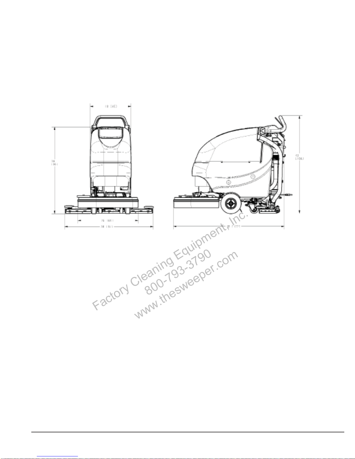
Machine Overview ......................................................................................................... 5
Controls .......................................................................................................................... 6
Bail Handle.............................................................................................................. 6
Handle Adjustment Knobs....................................................................................... 6
Key Switch............................................................................................................... 6
Direction Switch....................................................................................................... 6
Squeegee Lift Lever ................................................................................................ 6
Battery / Fault Gauge .............................................................................................. 6
Speed Control.......................................................................................................... 6
Charge Status Indicator........................................................................................... 6
Optional Hour Meter........................................................................................................ 7
Optional Pump Kit............................................................................................................ 7
Vacuum Hose Routing.....................................................................................................7
Circuit Breakers...............................................................................................................7
Battery Compartment ...................................................................................................... 8
Diagnostic Code Guide.................................................................................................... 8
Handle Adjustment .......................................................................................................... 9
Angle Adjustment..................................................................................................... 9
Horizontal Adjustment.............................................................................................. 9
Solution Tank Drain Hose.............................................................................................. 10
Solution Level Indicator.................................................................................................10
Solution Fill Filter...........................................................................................................10
Recovery Tank Drain Hose.............................................................................................11
Screened Float...............................................................................................................11
Screened Float Removal........................................................................................11
In-Line Solution Filter Assembly.................................................................................... 12
Rear Squeegee ............................................................................................................ 12
Cleaning the Squeegee................................................................................................. 12
Changing the Squeegee Blades.................................................................................... 12
Angle Adjustment .................................................................................................. 13
Height Adjustment ................................................................................................ 13
Brush Deck....................................................................................................................14
Brush Loading / Unloading ........................................................................................... 14
Aquastop Solution Control............................................................................................. 14
The Bulldog WD26....................................................................................................... 15
Machine Operation ...................................................................................................... 16
To Turn ON Machine:..................................................................................................... 16
To Turn ON Vacuum: ..................................................................................................... 16
To Turn ON Brush Motor:............................................................................................... 16
To Turn on Cleaning Solution: ....................................................................................... 16
Direction Switch:............................................................................................................ 16
Speed control: ............................................................................................................... 16
Driving: .......................................................................................................................... 16
To Charge Batteries:...................................................................................................... 16
Hour Meter (Optional):................................................................................................... 16
After Use....................................................................................................................... 16
Maintenance................................................................................................................. 17
Troubleshooting............................................................................................................. 18
Table Of Contents
Factory Cleaning Equipment, Inc.
800-793-3790
www.thesweeper.com

4
Safety Instructions
IMPORTANT SAFETY INSTRUCTIONS
Operators must read and understand this manual before operating or maintaining this machine.
Do not operate this machine in flammable or explosive areas.
This machine is designed solely for scrubbing dirt and dust in an indoor environment. The manufacturer does not recommend using
this machine in any other capacity.
The following information below may cause a potential hazard to the operator and equipment. Read this manual carefully and be aware
whentheseconditionscanexist.Takenecessarystepstolocateallsafetydevicesonthe machine and train the personnel operating the
machine.Reportanymachinedamageorfaultyoperation immediately. Do not use machine if it is not in proper operating condition.
FOR SAFETY DURING OPERATION
Keep hands and feet clear of moving parts while machine is in operation.
Make sure all safety devices are in place and operate properly. All covers, doors and latches must be closed and fastened before use.
During operation, attention should be paid to other persons in the work area and especially if small children are present.
Electricmotors and components can cause an explosion when operatednearexplosive materials or vapor. Do not operate this machine
near flammable materials such as solvents, thinners, fuels, grain dust, etc.
Storeor parkthis machine ona levelsurface only.To prevent unauthorizeduse, machineshould be storedor parkedwith the keyremoved.
This machine is designed for level operation only. Do not operate on ramps or inclines greater than 2%.
This machine is not suitable for picking up hazardous dusts.
Use caution when moving this machine into areas that are below freezing temperatures. Any water in the tanks or hoses can cause
damage to the machine.
FOR SAFETY WHEN SERVICING or MAINTAINING MACHINE
Stop on level surface.
Disconnect the power to the machine by unplugging the red Battery connector located under the recovery tank near the batteries.
Avoid moving parts. Do not wear loose jackets, shirts, or sleeves when working on machine.
Avoidcontact with battery acid. Battery acid can cause burns. When working on or around batteries, wear protective clothing and safety
glasses. Remove metal jewelry. Do not lay tools or metal objects on top of batteries.
Charging batteries generates explosive gasses.
Do not charge batteries when open flames or sparks are present. Do not smoke.
Make sure the charger is turned off before disconnecting it from the machine.
Charge the batteries in a well-ventilated area with the battery cover removed completely.
Do not clean machine with a pressure washer.
Authorized personnel must perform repairs and maintenance. Use Minuteman supplied replacement parts.
SAVE THESE INSTRUCTIONS
Inspection
Carefully unpack and inspect your Bulldog WD26 Walk-Behind Scrubber for shipping damage. Follow unpacking
instructions on shipping pallet. Each unit has been tested and thoroughly inspected before shipment. Any damage is
the responsibility of the delivery carrier who should be notified immediately.
Electrical
This machine is battery operated and designed to operate on 24 volts DC (2) 12-volt batteries.
Batteries
The recommended batteries are rated 140Ah WET (Manufacturer P/N 956140) or 95Ah Maintenance Free GEL
(Manufacturer P/N 956100). We do not recommend mixingAMP hour capacities. Alternate battery sets can be used
if they equal physical size and capacity. If alternate battery sets are used please contact the manufacturer for on
board charger settings.
Operator Responsibility
Read this manual carefully before operating this machine.
The operator is responsible for taking care of the daily maintenance and check ups of the machine to keep it in good
working condition. The operator must inform the service mechanic or supervisor when the scheduled maintenance
intervals are required as stated in the MAINTENANCE section of this manual.
Before starting familiarize yourself with the machine and its controls (see “Machine Overview, Front”, “Machine
Overview, Rear”, “Control Console” diagrams).
Factory Cleaning Equipment, Inc.
800-793-3790
www.thesweeper.com

5
Machine Overview
Machine Overview - Front
A CUP HOLDER
B SOLUTION FILL PORT
C RECOVERY TANK LID
D RECOVERY TANK
E BRUSH DECK
F FRONT WHEEL (see note)
G REAR CASTER
H SOLUTION TANK
* NOTE - Front tires are foam filled to be
maintenance-free. No air can be
added.
Machine Overview - Rear
A BAIL HANDLE
B SQUEEGEE LIFT LEVER
C RECOVERY TANK DRAIN HOSE
D ONBOARD CHARGER CORD
E CIRCUIT BREAKERS
F RECOVERY HOSE
G CONTROL PANEL
H SOLUTION TANK DRAIN HOSE /
LEVEL INDICATOR
J BRUSH DECK LIFT PEDAL
K REAR SQUEEGEE
L DIAGNOSTIC CODE GUIDE
M SOLUTION CONTROL LEVER
N DECK TILT HANDLE
Factory Cleaning Equipment, Inc.
800-793-3790
www.thesweeper.com

6
Machine Overview
A BAIL HANDLE
B HANDLE ADJUSTMENT KNOB
C KEY SWITCH
D DIRECTION SWITCH
E SQUEEGEE LIFT LEVER
F BATTERY / FAULT GAUGE
G SPEED CONTROL
H CHARGE STATUS INDICATOR
J SOLUTION CONTROL LEVER
K AQUASTOP SOLUTION SETTING
Controls
Bail Handle
(A) Whenthe scrub deckis lowered tothe floor, thebailhandle enables thebrush motor andmoves the machineforward once depressed.
Handle Adjustment Knobs
(B) Allows the handle position to be raised or lowered.
Key Switch
(C) Controls the machine’s power (Off/On) with a key for safety. When it is turned to the on position, the machine will operate (after 5
second diagnostic check, see battery gauge).
Direction Switch
(D) This 3 position switch sets the direction the machine will move when the bail handle is pulled. The middle position is neutral -
brushes & vacuum will operate but machine will not move.
Squeegee Lift Lever
(E) When moved to the top position, the squeegee is lowered and the vacuum motor is turned on. When locked in the bottom position,
the squeegee is raised and the vacuum motor shuts off (after a 10 second delay).
Battery / Fault Gauge
(F) This gauge displays the remaining battery charge. This gauge also displays any fault codes that might occur with the Drive Motor
Controller (see Diagnostic Codes). Gauge will blink for 5 seconds when key is first turned on, to run diagnostic check before machine
can be used.
Speed Control
(G) This control sets the speed at which the machine will move.
Charge Status Indicator
(H) This gauge displays the status of the batteries during charging. The gauge has a readout of 3 LEDs. 1 Green, 1 Yellow, 1 Red.
Green indicating a full charge, Yellow indicating 80% charged, Red indicating the batteries are charging.
Solution Control Lever
(J) This lever controls the rate at which solution is dispensed. Moving the lever up will increase the amount of solution. Moving the
lever down will decrease the amount. Moving the lever all the way down shuts off solution flow.
Aquastop Solution Setting
(K) This bracket is a guide to limit the amount of solution dispensed for consistent performance.
Factory Cleaning Equipment, Inc.
800-793-3790
www.thesweeper.com

7
Machine Overview
The Manufacturer offers an optional hour
meter for the Floor Srubber. The optional
kit replaces the power cord mounting
bracketat the rearof the machinewith one
that contains an hour meter.
Manufacturer’s
Kit# K-E1720HM
Optional Hour Meter
Optional Pump Kit
The Manufacturer offers an optional pump
kitfor thefloor scrubber.The pump will turn
on when the switch is toggled to the ON
position. Thehose to coupler fills, then the
pumpshutsoffuntilthe wand (notsupplied)
is connected and chemical is dispensed.
Kit# K-E1720P
TOGGLE SWITCH PUMP
Vacuum Hose Routing
Forbest results, routethe vacuum hoseas shown below:
Circuit Breakers
A Main Control Circuit Breaker - 4A
B Brush Motor Circuit Breaker - 30A
C Vacuum Motor Circuit Breaker - 20A
D Drive Motor Circuit Breaker - 20A
The circuit breakers are located at the bottom of
the back panel of the machine.
If any of the functions above are not operating,
check if the circuit breaker buttons have tripped.
Press to reset.
BCAD
Factory Cleaning Equipment, Inc.
800-793-3790
www.thesweeper.com

8
Machine Overview
The battery compartment is located under the recovery tank. The
Battery compartment can be accessed for servicing and mainte-
nance by tilting the recovery tank (make sure recovery tank has
been drained before tilting). The battery compartment contains
two 12-volt batteries connected in series. Connect the batteries
according to the battery connection diagram (see diagram). The
recommended batteries are 140Ah (manufacturer’s P/N 956140)
or 95Ah (manufacturer’s P/N 956100) Gel. The battery tray may
bedrained if necessaryusing the orange drainhose located above
the rear caster on the right side of the machine.
Battery Compartment
Diagnostic Code Guide
Whenan error orfault occurs withinthe machine, a fault code will appearon the batterygauge represented
by a specified number of flashing LEDs. (See “Troubleshooting” for further information)
Factory Cleaning Equipment, Inc.
800-793-3790
www.thesweeper.com

9
Machine Overview
Handle Adjustment
The WD26 handle was designed with operator comfort
inmind. The angle and horizontal position of the handle
can be adjusted to suit the needs of the operator.
Angle Adjustment
The handle angle can be adjusted without tools by
looseningtheAngleAdjustment Knob (A) oneachside
and rotating the handle to the desired position. There
are 5 angular positions 11.25° apart for a total of 45°
between the minimum and maximum position.
A
Horizontal Adjustment
The horizontal position can be adjusted by removing
the 4 Mounting Bolts (B) (2 each side) with a 9/16”
socket and sliding the Mounting Plate (P) to one of the
3 available positions. The machine is shipped from the
factory in position 1.
123
PB
Plate Position 1
(Shipping Position)
Plate Position 2Plate Position 3
(Fully Extended)
Factory Cleaning Equipment, Inc.
800-793-3790
www.thesweeper.com

10
Machine Overview
Solution Tank Drain Hose
Thesolutiontankmay bedrainedby removingtheSolution
Tank Drain Hose (A) from the Hose Barb (B) and routing
the hose to a floor drain.
AB
Solution Level Indicator
The Solution Tank Drain Hose also serves as a water
level indicator for the solution tank. The amount of water
remaining in the solution tank can be seen through the
clear drain hose. Level markers molded into the solution
tank are positioned at 1/4, 1/2, 3/4, and full levels.
Solution Fill Filter
The Solution Fill Filter (B) should be cleaned regularly. To remove, simply open the Solution Tank Lid
(A) and pull the filter out.
A
B
Factory Cleaning Equipment, Inc.
800-793-3790
www.thesweeper.com

11
Machine Overview
Recovery Tank Drain Hose
Twist Cap to Open and Drain Twist & Lift cap to clean out debris
Note: Debris left on the o-ring will cause a vacuum leak.
Screened Float
If the recovery tank (C) is overfilled or a large amount of
foaming is present, the screened float (B) blocks the vacuum
intakeinsidethe tankprotectingthe vacuummotor and internal
electronicsfrom waterdamage. It isessential to keep the float
in working order through regular maintenance.
The float should be cleaned daily by thoroughly rinsing with
a hose. Removal of the screened float is not necessary for
daily maintenance.
Atleast oncea monththe screened float should be completely
removed, cleaned, and checked for any damage to the seal
or metal screen.
WARNING: Damage to the machine may occur if operated
without the screened float properly in place.
C
A
B
Screened Float Removal
Thescreenedfloatis positionedbetween thevacuum manifold
(A) and recovery tank (C). The screened float (B) can be
accessed by removing the 1.5” bolt (D) and two 1.25” bolts
(E) that attach the manifold to the recovery tank using a 7/16”
socket.
A Vacuum Manifold
B Screened Float
C Recovery Tank
D 1.5” Bolt
E 1.25” Bolt (2)
F Helical Washer (3)
G Flat Washer (3)
A
F
B
D
E
G
E
Factory Cleaning Equipment, Inc.
800-793-3790
www.thesweeper.com

12
Machine Overview
ABD
C
The solution solenoid, which shuts off solution flow when the bail handle is released, is protected from debris by the in-line filter
assembly. The filter assembly is located at therearof the machine on the left hand side, just underthe solution tank. It is important
to check and clean the screened washer inside the assembly regularly to ensure proper solution flow. To open, unscrew the
assembly (Note that the cone of the washer is facing out toward the rear of the machine). Remove washer and rinse, reinsert
and screw assembly together, tightening by hand. Overtightening with tools may damage the plastic threads.
A Fitting, MGHT
B Screened Washer
C Hose Barb Insert
D Fitting, FGHT
In-Line Solution Filter Assembly
Rear Squeegee
A Squeegee
B Star-shaped knob
C Adjusting screw for angle adjustment
D Suction hose
E Blade fastening latch
F Washers for caster height adjustment
G Caster Wheel Axle
Cleaning the Squeegee
Check the squeegee (A) daily and clean
as necessary.
1. Pull off the suction hose (D).
2. loosen the two star-shaped knobs (B).
3. Remove the squeegee (A).
Changing the Squeegee Blades
Check the inner and outer squeegee
blades on the squeegee (A) weekly for
signs of wear. The squeegee blades can
be reused by turning them (can be turned
for 4 total uses).
1. Pull off the suction hose (D), loosen the
two star-shaped knobs (B) and remove
the squeegee.
2. Unlock the fastening device (E) and
remove the outer squeegee blade. Turn
the squeegee blade or install a new
one, as necessary. Change the inner
squeegee blade in the same way.
Factory Cleaning Equipment, Inc.
800-793-3790
www.thesweeper.com

13
Machine Overview
The angle adjustment is the decisive factor
in ensuring that the squeegee blades on the
squeegee lie evenly on the floor.
1. Park the machine on a level surface and lower
the squeegee.
2. Loosen the lower wing nut (B) on the adjusting
screw(A) andadjustthesqueegee usingthe ad-
justing screw so that the ends of the squeegee
bladesstill havecontact withthe floor.By turning
the adjusting screw (A) counterclockwise, the
clearancebetween squeegee blade and flooris
increased in the center (Fig. 1). When turning
theadjusting screw(A) clockwise,the clearance
between squeegee blade and floor is reduced
in the center (Fig. 2).
3. Switch the machine on and check the suction
pattern. When the machine is in operation, the
entire surface of the squeegee blades (center
and outer areas) must be applied as evenly as
possible.
4. Tighten the lower wing nut (B) on the adjusting
screw (A) against the metal bracket to lock in
the pitch setting.
A
B
B
A
2
1
Squeegee Blades
Angle Adjustment
Squeegee Blades
Height Adjustment
If streaks are present, despite an optimum angle
adjustment, the clearance between the caster
wheelsand floormust beadjusted by changingthe
number of washers underneath the bracket that
holds the wheel. The squeegee height is preset
at the factory to 3mm.
In cases of very smooth floors, e.g. finished
floors, PVC, linoleum, etc., see 2mm illustration
for washer configuration.
Incases of very unevenfloors, e.g. poorly laidtiles
(water does not run off) ,, configure as shown in
4mm illustration.
Keep the extra washers by installing
them above the bracket as shown.
Factory Cleaning Equipment, Inc.
800-793-3790
www.thesweeper.com

14
Machine Overview
1. Brush Deck may be tilted up for
easier brush installation/removal
& to clear steep ramps. Lift the
handle on the upper lever which
connects the brush deck to the
machine, tilt the deck up, release
the handle & the lever will lock
into place. Lift the handle again to
move the deck back to horizontal.
2. Brushes are installed/removed
by hand. Push each brush up
onto the hub until it “clicks”. To
remove, pull down on the edge of
each brush.
3. The splash guard may be moved
upordown asthebrush/pad wears
by loosening the clamp on the
back side of the deck with a flat-
head screwdriver or 9/32” (7mm)
socket,then slidethe splashguard
to the desired height & retighten
the clamp.
Brush Loading / Unloading
Brush Deck
Aquastop Solution Control
In order to consistently conserve water when using Aquastop brushes, the guide will stop the solution control lever
at a low rate setting. This setting may be adjusted by loosening the knob, adjusting the lever, and retightening the
knob. Slide the knob all the way forward to dispense maximum solution.
Factory Cleaning Equipment, Inc.
800-793-3790
www.thesweeper.com

15
This machine was designed with total operator comfort and ease of use in mind. All machine components have
been designed as a total system to efficiently clean dirty floors. Please contact your representative for specific
recommendations for the correct brush type and chemical applications.
Before using the machine, always perform the following steps to ensure proper machine operation:
• Check under the machine for leaks.
• Check the rear squeegee for wear and damage.
• Check the solution and recovery tank levels.
After using the machine, always perform the following steps:
• Check the battery charge level. Charge batteries if necessary. When charging batteries, extra precaution is
required:
- Battery acid can cause burns.
- When working on or around batteries, always wear protective clothing and safety glasses.
- Remove metal jewelry. Do not lay tools or metal objects on top of the batteries.
- Charging batteries generate explosive gasses.
DO NOT CHARGE BATTERIES WHEN OPEN FLAMES OR SPARKS ARE PRESENT. DO NOT SMOKE.
- Charge the batteries in a well-ventilated area.
-Fluid levels shouldbe checked beforeand after chargingand maintained atthe proper levels.If low, add distilled
water until the metal plates are covered.
- If the machine is not used for an extended period of time, batteries should be kept fully charged with a boost
charge once a week.
• Check for wire, string, or twine wrapped around the scrub brushes.
• Check the rear squeegee for wear and damage.
• Check the rear squeegee suction hose for obstructions.
• Drain and rinse the recovery tank.
• Check under the machine for leaks.
• Check the service records to determine maintenance requirements.
WARNING!
- Be sure you understand the machine controls and their functions.
- While on ramps or inclines, avoid sudden stops when tanks are filled.
- Avoid abrupt sharp turns. Slow down driving speed when going downhill.
The Bulldog WD26
Factory Cleaning Equipment, Inc.
800-793-3790
www.thesweeper.com

16
Machine Operation
To Turn ON Machine:
Turn key tooperate position (I ). Waitfor battery gauge tostop flashing, approximately5 seconds. (If flashingcontinues,
see troubleshooting guide)
To Turn ON Vacuum:
Lower squeegee into operating position, vacuum motor will turn ON automatically.
To Turn ON Brush Motor:
Lower the scrub deck to the floor by moving the brush lift pedal from the “home” (down) position to the operating position
(up). Depress the operator bail handle. Brush motor will turn ON.
To Turn on Cleaning Solution:
Movesolution lever fromclosed (down) positionup to the desired flow position. With thescrub deck onthe floor, depress
the bail handle, solution will begin to flow.
Note: An electronic solution solenoid valve will stop solution flow whenever the bail handle is released.
Direction Switch:
Select direction of machine by moving the directional rocker switch from the neutral position to the forward or reverse
position. The direction of the machine movement is shown on the operator panel with forward and reverse arrows.
Speed control:
Move the speed dial to the desired position. Turning the dial clockwise increases the speed. Turning the dial
counterclockwise decreases the speed.
Driving:
Depress the operator bail handle, the machine will move in the direction selected.
To Charge Batteries:
When the battery / fault gauge reaches the red zone the batteries need to be recharged. Take the machine to a well
ventilated area, unwind the battery charger power cord from the electrical box cover and plug into an appropriate
power source. After approximately 10 seconds the battery charge status indicator will turn on. Check the battery water
levels before each use, refill as needed with distilled water. Caution: do not overfill. Fill water 1/4 “ - 1/2” above the
separators. Failure to maintain the batteries may result in battery failures.
WARNING: Charging batteries generates explosive gasses. Do not charge batteries when open flames or sparks
are present. Do not smoke. Charge the batteries in a well-ventilated area .
Hour Meter (Optional):
Hour meter will automatically record operating time of the brush motor.
After Use
1. When finished scrubbing, lift the scrub deck. Lift the rear squeegee (the vacuum motor will turn off after 10 seconds).
Move the machine to a service area for daily maintenance and review items that may need service.
2. Empty the solution tank by disconnecting the solution tank drain hose from the barb fitting and routing hose to a
drain. Rinse the tank with clean water to prevent any buildup of dried chemicals that could clog the plumbing.
3. Empty and clean the recovery tank by flushing with a hose. Be sure to also clean the float shut off screen.
4. Remove the brushes or pad holders and rinse them in warm water and hang to dry.
5. Remove the rear squeegee and recovery hose, rinse with warm water and reinstall after cleaning (see page 13
for correct hose installation).
6. Check the maintenance schedule in the next section and perform any required maintenance before storing the
machine.
7. Store the machine indoors in a clean dry place. Keep from freezing. Leave solution and recovery tank lids open for
ventilation to prevent odor buildup.
8. Turn Key switch OFF (O) and remove key.
Factory Cleaning Equipment, Inc.
800-793-3790
www.thesweeper.com

17
Maintenance
Have a qualified service technician check the vacuum motor carbon motor brushes once a year or after 300 operating hours.
The brush motor and transaxle motor carbon brushes should be checked every 500 hours or once a year.
NOTE: Refer to the Service Manual for more detail on maintenance and service repairs.
Regularly scheduled lubrication of certain machine parts should be performed to insure trouble-free operation of
the machine. Apply a generous amount of grease into the fittings on the machine until grease seeps out around
the bearings.
The grease points are listed below:
• Rear caster swivel (2)
Apply lubricant or light machine oil to lubricate the:
• Pivot mounting point of the squeegee lift mechanism to the chassis (1)
• Rear squeegee caster wheel axle (2)
Daily Weekly Monthly Yearly
Charge Batteries Inspect Brush Deck
Splash Guard for Debris Lubrication - Grease
Fittings Check Carbon
Brushes
Check/Clean Tanks and
Hoses Inspect and Clean In-Line
Solution Filter
Check/Clean/Rotate
the Brushes Rinse off the underside of
Brush Deck
Check/Clean the
Squeegee Check each Battery Cell
(s) Water Level
Check/Clean Vacuum
Shut-Off Float in
Recovery Tank
Factory Cleaning Equipment, Inc.
800-793-3790
www.thesweeper.com

18
Troubleshooting
Problem Possible Cause Remedy
Worn or torn squeegee blades Rotate or replace blades
Recovery tank full Empty recovery tank
Recovery tank drain hose leak Clean and secure drain hose cap or replace
Poor water pick up Recovery tank lid gasket leak Replace gasket lid cover properly
Debris caught in squeegee Clean squeegee
Vacuum hose clogged Remove debris and flush hose
Recovery hose to squeegee or recovery tank
disconnected/damaged Reconnect or replace recovery hose
Worn brush or pad Replace brush or pad
Wrong brush or cleaning chemical Consult manufacturer
Debris caught on scrub brush Remove debris
Poor scrubbing performance Moving machine too fast Slow down for more complete scrubbing
Not using enough solution Adjust solution flow setting
Low battery charge Recharge batteries
Solution tank empty Fill solution tank
Inadequate solution flow or no Solution lines, filter , or valves clogged Flush lines and clean solution filter
solution to the floor Solution Lever in down position Raise lever up
Squeegee is down and directional switch is in
reverse position Raise squeegee when in reverse mode
Machine does not move Traction drive circuit breaker has tripped Reset circuit breaker
Batteries lost power Recharge batteries
Directional switch in neutral position Activate FWD or REV position
Tripped control power circuit breaker Reset breaker
Batteries have low charge Recharge batteries
Machine does Battery charger operating Unplug battery charger when charge is complete
not operate Key switch off Turn key on
Bail handle depressed too quickly after turning
key on Turn key off, turn on, wait until battery gauge
lights up without flashing
Recovery tank full Empty recovery tank
Excessive foam in recovery tank
Empty recovery tank, rinse off the screened float,
inside recovery tank
Use less or change chemical
Use defoaming agent
Vacuum motor Carbon brushes worn Replace carbon brushes
does not turn on Tripped vacuum motor circuit breaker Reset breaker
Broken vacuum limit switch Replace switch by squeegee lift lever
Squeegee in raised position Lower squeegee
Charger not plugged to wall outlet Plug into wall outlet
Batteries do not Circuit breaker tripped in wall outlet Reset breaker
charge Battery disconnected from machine Connect battery to machine
Charger malfunction Call service
Foot pedal not in the “home” position Place pedal in notch
Brush does not Tripped brush motor circuit breaker Reset breaker
unload Broken brush motor switch Replace switch
Damaged brush block or drive hub Replace
Factory Cleaning Equipment, Inc.
800-793-3790
www.thesweeper.com

19
Troubleshooting
Charger Warning Indicators
LED status Description
Warning RED LED lamp blinks
once Output open circuit or short circuit or reverse polarity connection of charger to
battery. Battery voltage is too high (may be connected to wrong voltage battery).
RED LED lamp blinks
twice Abnormal cycle (may be weak or bad battery). Charging time has safety timed
out due to battery problem.
The battery needs charging,
there is a bad connection to
the battery or dependent on
programming, may indicate that
the battery lockout function is
active and the controller is in a
restricted mode of operation.
Check the connections to the
battery. If the connections are
good, try charging the battery.
There is a bad connection to the
motor. Check all connections
between the motor and the
controller.
The motor has a short circuit to a
batteryconnection. Contact your
service agent.
The battery charge level
has fallen below the Battery
Lockout level and the controller
is inhibiting certain machine
functions. Charge the battery.
Fault / Diagnostic Codes
TheBattery / Fault gauge will flash when a faultis detected. Adecallabeled “Diagnostic Codes” is located below the battery gauge
as an abbreviated and convenient guide to determine the cause of the fault and the remedy (refer to machine or see “Diagnostic
Code Guide” section of this manual). The flashing codes are for the following:
Not used.
The controller is being inhibited
fromdriving,thismay bebecause
thebattery charger is connected.
The bail handle was activated prior
to turning the machine on. Make
sure that the bail handle is in the
rest position. Restart the key switch.
A controller fault is indicated. Make
sure that all connections are secure.
Not used.
An excessive voltage has been
applied to the controller. This is
usually caused by a poor battery
connection. Check the battery
connections.
Factory Cleaning Equipment, Inc.
800-793-3790
www.thesweeper.com

WARRANTY
Bulldog Scrubbers warrants to the original purchaser/user that the product is free from defects in
workmanship and materials under normal use. Bulldog Scrubbers will, at its option, repair or replace without
charge, parts that fail under normal use and service when operated and maintained in accordance with the
applicable operation and instruction manuals. All warranty claims must be submitted through and approved
by factory authorized repair stations.
This warranty does not apply to normal wear, or to items whose life is dependent on their use and care, such
as belts, cords, switches, hoses, rubber parts, electrical motor components or adjustments. Parts
manufactured by Bulldog Scrubbers are covered by and subject to the warranties and/or guarantees of their
manufacturers. Please contact Bulldog Scrubbers for procedures in warranty claims against these
manufacturers.
Special warning to purchaser -- Use of replacement filters and/or pre-filters not manufactured by Bulldog
Scrubbers or its designated licensees, will void all warranties expressed or implied. A potential health hazard
exists without original equipment replacement.
All warranted items become the sole property of Bulldog Scrubbers or its original manufacturer, whichever
the case may be.
Bulldog Scrubbers disclaims any implied warranty, including the warranty of merchantability and the warranty
of fitness for a particular purpose. Bulldog Scrubbers assumes no responsibility for any special, incidental or
consequential damages.
This limited warranty is applicable only in the U.S.A. and Canada, and is extended only to the original
user/purchaser of this product. Customers outside the U.S.A. and Canada should contact their local distributor
for export warranty policies. Bulldog Scrubbers is not responsible for costs or repairs performed by persons
other than those specifically authorized by Bulldog Scrubbers. This warranty does not apply to damage from
transportation, alterations by unauthorized persons, misuse or abuse of the equipment, use of non-
compatible chemicals, or damage to property, or loss of income due to malfunctions of the product.
If a difficulty develops with this machine, you should contact the dealer from whom it was purchased.
This warranty gives you specific legal rights, and you may have other rights which vary from state to state.
Some states do not allow the exclusion or limitation of special, incidental or consequential damages, or
limitations on how long an implied warranty lasts, so the above exclusions and limitations may not apply to
you.
Bulldog Scrubbers
877-292-3935
www.bulldogscrubbers.com
Factory Cleaning Equipment, Inc.
800-793-3790
www.thesweeper.com
Table of contents