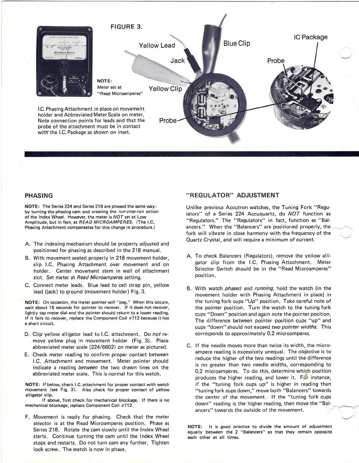
manuals.online logo
Brands
  1. Home
  2. •
  3. Brands
  4. •
  5. Bulova
  6. •
  7. Watch
  8. •
  9. Bulova Accuquartz 224 Series Service manual

Bulova Accuquartz 224 Series Service manual

INTRODUCTION
Accuquartz
Series 224
The Series 224 Accuquartz is basically an Accutron® Series
218 with some modifications. The most significant difference
is the addition of a Quartz Crystal Oscillator to an already
proven and established timepiece. Although some parts, regu-
lation and minor adjustments may differ, the Series 224 and
Series 218 are very similar to each other in basic servicing
procedures.
The basic tools and equipment necessary for servicmq the
Accutron Series 218 are also employed in servicing the Accu-
~. quartz 224. In addition, a Quartz Crystal Deviation Counter -
with 32,768 Hz pickup is required . ., When phasing, an I.C.
(integrated circuit) Phasing Attachment (Accuquartz Service
Kit #224/6601) is used in conjunction with the basic 218
movement holder. Also, an abbreviated meter scale is neces-
sary. (Accuquartz Service Kit #224/6602).
~~ ..u;.
Tools
FIGURE 2.
BUlOVA ACCUQUARTZ SERIES
224
Service Kit #224/6602,
Abbreviated Meter Scale.
Servicing
FIGURE 1.
Series 224 Movement, train side.
SPECI FICATIONS
Quartz Frequency
32,768 Hz (cycles per second)
Tuning Fork Frequency
3411/3 Hz (cycles per second)
Jewels
15
Dimensions
25.75mm x 4.4mm (6.1mm height
with calendar)
Service Kit #224/6601,
I.C. Phasing Attachment Ligne Size
12%
Power Source
Bulova 218, or Accutron 218
Displays
Model 2240-Hour, Minute and Sweep
Second
Model 2241-Hour, Minute, Sweep Second
and Date
Model 2242-Hour, Minute, Sweep Second,
Day and Date
Disassembly, cleaning, lubrication and reassembly including
calendar, INDEX ADJUSTMENT and PHASING (with a minor
variation) is done in exactly the same manner as the Series 218.
When necessary, please refer to the 218 manual for servicing
'~h' Accuquartz 224. \ /
q;
L\
'1
7
~~rI. .
..
,
FIGURE 3.
NOTE:
Meter setat
Read Microamperes
I.C.PhasingAttachment in place on movement
holder and Abbreviated Meter Scale on meter.
Note connection points for leads and that the
probe of the attachment must be in contact
withthe I.C.Packageasshown on inset.
PHASING
NOTE: The Series224 and Series218 are phasedthe sameway:
by turning the phasingcam and creating the
run-stop-run
action
of the Index Wheel. However,the meter is
NOT
set at Low
Amplitude, but in fact, at
READ MICROAMPERES.
(The I.C.
PhasingAttachment compensatesfor this changein procedure.l
A. The indexing mechanism should be properly adjusted and
positioned for phasing asdescribed in the 218 manual.
B. With movement seated properly in 218 movement holder,
slip I.C. Phasing Attachment over movement and on
holder. Center movement stem in wall of attachment
slot. Set meter at
Read Microamperes
setting.
C. Connect meter leads. Blue lead to cell strap pin, yellow
lead (jack) to ground (movement holder) Fig. 3.
NOTE: On occasion, the meter pointer will peg. When this occurs,
wait about 15 secondsfor pointer to recover. If it does not recover,
lightly tap meter dial and the pointer should return to a lower reading.
tf it fails to recover, replace the Component Coil #712 becauseit has
a short circuit.
D. Clip yellow alligator lead to I.C. attachment. Do
not
re-
move yellow plug in movement holder (Fig. 3). Place
abbreviated meter scale (224/6602) on meter aspictured.
E. Check meter reading to confirm proper contact between
I.C. Attachment and movement. Meter pointer should
indicate a reading
between
the two drawn lines on the
abbreviated meter scale. This is normal for this watch.
NOTE: If below, check I.C.attachment for proper contact with watch
movement (see Fig. 3). Also check for proper contact of yellow
alligator clip.
If above, first check for mechanical blockage. If there is no
mechanical blockage, replaceComponent Coil #712.
F. Movement is ready for phasing. Check that the meter
selector is at the Read Microamperes position. Phaseas
Series 218. Rotate the cam slowly until the Index Wheel
starts. Continue turning the cam until the Index Wheel
stops and restarts. Do not turn cam any further. Tighten
lock screw. The watch is now in phase.
REGULATOR ADJUSTMENT
Unlike previous Accutron watches, the Tuning Fork Regu-
lators of a Series 224 Accuquartz, do
NOT
function as
Regulators. The Regulators in fact, function as Bal-
ancers. When the Balancers are positioned properly, the /_,/~
fork will vibrate in close harmony with the frequency of the
Quartz Crystal, and will require a minimum of current.
A. To check Balancers (Regulators), remove the yellow alli-
gator clip from the I.C. Phasing Attachment. Meter
Selector Switch should be in the Read Microamperes
position.
B. With watch
phased
and
running
hold the watch (in the
movement holder with Phasing Attachment in place) in
the tuning fork cups Up position. Take careful note of
the pointer position. Turn the watch to the tuning fork
cups Down position and again note the pointer position.
The difference between pointer position cups up and
cups down should not exceed
two pointer widths.
This
corresponds to approximately 0.2 microamperes.
C. If the needle moves more than twice its width, the micro-
ampere reading is excessively unequal. The objective is to
reduce the higher of the two readings until the difference
is no greater than two needle widths, corresponding to
0.2 microamperes. To do this, determine which position
produces the higher reading, and lower it. Fo'r instance,
if the tuning fork cups up is higher in reading than
tuning fork cupsdown, move both Balancers towards
the center of the movement. If the tuning fork cups
down reading is the higher reading, then move the Bal-. . .-
ancers towards the outside of the movement. - /'
-r-=-/
\....,//
NOTE: It is good practice to divide the amount of adjustment
equally between the 2 Balancers so that they remain opposite
each other at all times.
FIGURE 4.
-
••...
;~
-,,'~-'
Yellow Clip
NOTE:
Meter set at
Read Microamperes
Current Drain Check. Note that the con-
nections differ from those shown in Figure
3
in that the yellow alligator clip is NOT
connected to the I.C. Phasing Attachment.
CURRENT DRAIN CHECK
A. After adjusting the Balancers with the
selector switch still set at Read Micro-
amperes, check that the reading does
NOT exceed Max. Run Current. Leads
are connected as in Fig.
4;
that is, yellow
alligator clip is NOT attached to I.C.
Phasing Attachment.
B. If current drain is above Max. Run Cur-
rent, then check for possible causes as
in Series 218. See Hints on back page.
FREQUENCY CHECK
Set the frequency counter selector
at 32,768 Hz.
TUNINGj
CAPACITOR
ASSEMBL Y
Checking the frequency of the Quartz Crystal
(32,768 Hz) is done by pulling the stem to
the setting (out) position and placing the
movement on the frequency counter pick-up.
The rate is adjusted solely by changing the
number and/or position of Tuning Capacitor
Screws (#352) located on the Component
Coil (#712). The AMOUNT and LOCATION
of screws adjust the frequency (Table 1).
FIGURE 5.
Electronic Circuit.
GROUND
LUG
O .J
TABLE I
NOMINAL VALUES
FOR THE 6 TUNING CAPACITOR SCREWS
Screw #1
Parts per Million 0.4 to 1.0
Seconds/day 0.03 to 0.10
A.
If frequency too
fast-Increase the ca-
pacitance of the tuning capacitor, thereby
decreasing the frequency, by
adding
or
relocating
one or several capacitor screws.
This reduces the frequency. See Table 1.
Screw #2
Parts per Million 0.9 to 2.1
Seconds/day 0.07 to 0.20
Screw #3
Parts per Million 1.8 to 4.2
Seconds/day 0.15 to 0.40
Screw #4
Parts per Million 3.6 to 8.5
Seconds/day 0.30 to 0.80
Screw #5
Parts per Million 7.2 to 17.6
Seconds/day 0.60 to 1.50
B.
If frequency too slow-Reduce
the ca-
pacitance of the tuning capacitor, thereby
increasing the frequency, by
removing
or
relocating
one or several tuning capacitor
screws. This increases the frequency.
See Table 1.
NOTE: After making a frequency adjustment, al-
low the watch to lie flat for a few minutes before
placing it on the frequency counter once more:
this allows the Quartz Crystal to stabilize. The
design of the watch is such that accuracy within
three minutes a year is not unusual.
Screw #6
Parts per Million 14.4 to 35.2
Seconds/day 1.20 to 3.00
LIST OF PARTS FOR SERIES 224
ADDITIONAL TO OR VARYING FROM SERIES 218
-
-.
103 Second Wheel 205 Setting Lever 609 Lead Strap Separator
'--
105 Third Wheel 209 Setting Lever Screw 709 Pillar Plate
112 Index Wheel 315 I.C. Ground Screw 712 Component Coil Assembly
141 Cell Strap 352 Tuning Capacitor Screw 715 Cell Coil Assembly
151 Cell Coil Screw 404 Train Bridge *716 Tuning Fork
151 Component Coil Screw 606A Lead Strap stand-off 814 Cell Strap Stand-off tube
151 Lead Strap Screw
*The Series224 Tuning Fork, being of different frequency is
not
interchangeable with
the Series218. To distinguish one from the other, examine the left cup. The Series
224 has a countersunk indent (dimple); The Series 218 does not.
FIGURE 6.
Cell Coil #715 Continuity Check
Components of Series 224. Shaded com-
ponents are only available as a single unit
specified as Part No. 712 (Component
Coil Assembly).
HINTS
1. To determine whether a Zero meter reading is due to an
open Component Coil #712 or an open Cell Coil #715, set
meter selector at low amplitude and carefully place yellow
lead to lower #715 lead strap, blue lead to ground lug, Fig. 6.
If meter pegs, #715 is o.k. and #712 is open and must be
replaced. If meter needle remains at zero then the #715 is
\,..J-
open and must be replaced.
2. Check Quartz Crystal Canister and I. C. Board. They must
be cemented tightly in place. If loose, cement in place
with Aron Alpha epoxy or equivalent. USE SPAR INGL YI As
with all Quartz Crystal Watches, care should be taken not to
subject the Quartz Crystal to abuse when movement is uncased.
3. It is imperative that the Tuning Fork be positioned properly
between the shoulders on the underside of the train bridge and
the pillar plate. Space between fork tines and train bridge
should be approximately twice the distance as that between
tines and pillar plate.
4. The tuning fork in an Accuquartz is a slave, whose accuracy
is controlled by the Quartz Crystal. Therefore, if a problem
exists within the accuracy of the watch, which cannot be ad-
justed by regulating, and there is no mechanical problem, it is
the Component Coil (#712), which contains the Quartz Crystal,
that needs to be replaced. On the other hand, if the meter
current drain is excessive, and there is no mechanical problem,
it is usually a demagnetized fork that is causing the high cur-
rent reading. The Tuning Fork must be replaced.
5. Check frequency, electronic circuit, and current drain before
assembling gear train to eliminate unnecessary assembly and
disassembly if problem exists.
All information contained in this booklet is based on the latest product information available at the time of printing.
Printed in U.S.A. Technical Information Services, Bulova Watch Company, lnc., 75-20 Astoria Blvd., Jackson Heights, N.Y. 11377. IA

Other Bulova Watch manuals

Bulova VD53 Service manual

Bulova

Bulova VD53 Service manual

Bulova 540S Service manual

Bulova

Bulova 540S Service manual

Bulova 100 Meter 98U13 User manual

Bulova

Bulova 100 Meter 98U13 User manual

Bulova 98A179 User manual

Bulova

Bulova 98A179 User manual

Bulova Time Zone Service manual

Bulova

Bulova Time Zone Service manual

Bulova Chronograph Service manual

Bulova

Bulova Chronograph Service manual

Bulova COMPUTRON 96C139 User manual

Bulova

Bulova COMPUTRON 96C139 User manual

Bulova Maquina 98A177 User manual

Bulova

Bulova Maquina 98A177 User manual

Bulova 96B358 User manual

Bulova

Bulova 96B358 User manual

Bulova PRECISIONIST CHRONO Service manual

Bulova

Bulova PRECISIONIST CHRONO Service manual

Bulova BVA-SERIES 100 Operating and maintenance manual

Bulova

Bulova BVA-SERIES 100 Operating and maintenance manual

Bulova Series 218 User manual

Bulova

Bulova Series 218 User manual

Bulova 45C20 Service manual

Bulova

Bulova 45C20 Service manual

Bulova Chrono FS00 Service manual

Bulova

Bulova Chrono FS00 Service manual

Bulova 98B118 Service manual

Bulova

Bulova 98B118 Service manual

Bulova CHRONO G10 Service manual

Bulova

Bulova CHRONO G10 Service manual

Bulova 43C32 Service manual

Bulova

Bulova 43C32 Service manual

Bulova 98B267 User manual

Bulova

Bulova 98B267 User manual

Bulova ANALOG T200 Service manual

Bulova

Bulova ANALOG T200 Service manual

Bulova MARINE STAR Series User manual

Bulova

Bulova MARINE STAR Series User manual

Bulova Accu-Swiss series User manual

Bulova

Bulova Accu-Swiss series User manual

Bulova 11 ANAC Service manual

Bulova

Bulova 11 ANAC Service manual

Bulova VD53 Instruction manual

Bulova

Bulova VD53 Instruction manual

Bulova OS20 Series Service manual

Bulova

Bulova OS20 Series Service manual

Popular Watch manuals by other brands

Garmin fenix Quick start manual

Garmin

Garmin fenix Quick start manual

Samsung Galaxy Watch Active troubleshooting guide

Samsung

Samsung Galaxy Watch Active troubleshooting guide

Garmin Forerunner 405 owner's manual

Garmin

Garmin Forerunner 405 owner's manual

Technaxx TrendGeek TG-SW1 user manual

Technaxx

Technaxx TrendGeek TG-SW1 user manual

VibraLITE 8 user manual

VibraLITE

VibraLITE 8 user manual

TFA 38.2030 instruction manual

TFA

TFA 38.2030 instruction manual

Mondia ETA 2824 operating instructions

Mondia

Mondia ETA 2824 operating instructions

Navigil S1 user guide

Navigil

Navigil S1 user guide

Casio 5228 Operation guide

Casio

Casio 5228 Operation guide

Oceanic ATOM 2.0 operating manual

Oceanic

Oceanic ATOM 2.0 operating manual

BREIL CHRONO FS10 Instruction book

BREIL

BREIL CHRONO FS10 Instruction book

Eurotops BK613 instruction manual

Eurotops

Eurotops BK613 instruction manual

Patek Philippe P2414 manual

Patek Philippe

Patek Philippe P2414 manual

Chronos Manufactures MLG-2100 instruction manual

Chronos Manufactures

Chronos Manufactures MLG-2100 instruction manual

Raymond Weil NABUCCO CUORE CALDO Instructions for use

Raymond Weil

Raymond Weil NABUCCO CUORE CALDO Instructions for use

Sunsky S1 Plus user manual

Sunsky

Sunsky S1 Plus user manual

Sigma iD.FREE user guide

Sigma

Sigma iD.FREE user guide

Breitling Colt Chronograph II user guide

Breitling

Breitling Colt Chronograph II user guide

manuals.online logo
manuals.online logoBrands
  • About & Mission
  • Contact us
  • Privacy Policy
  • Terms and Conditions

Copyright 2025 Manuals.Online. All Rights Reserved.