Page 2
INTRODUCTION
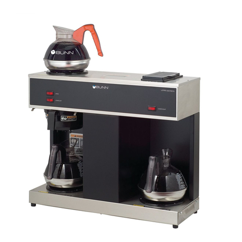
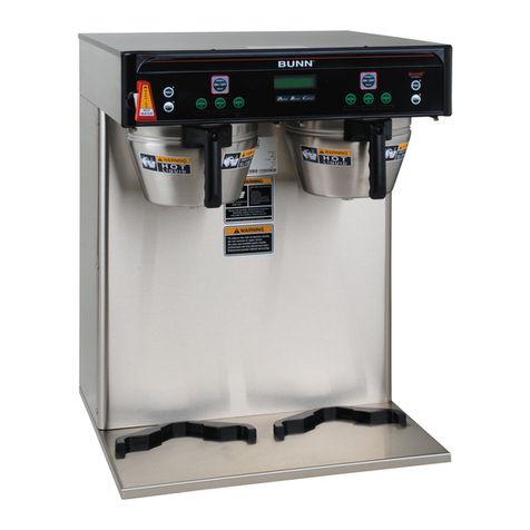
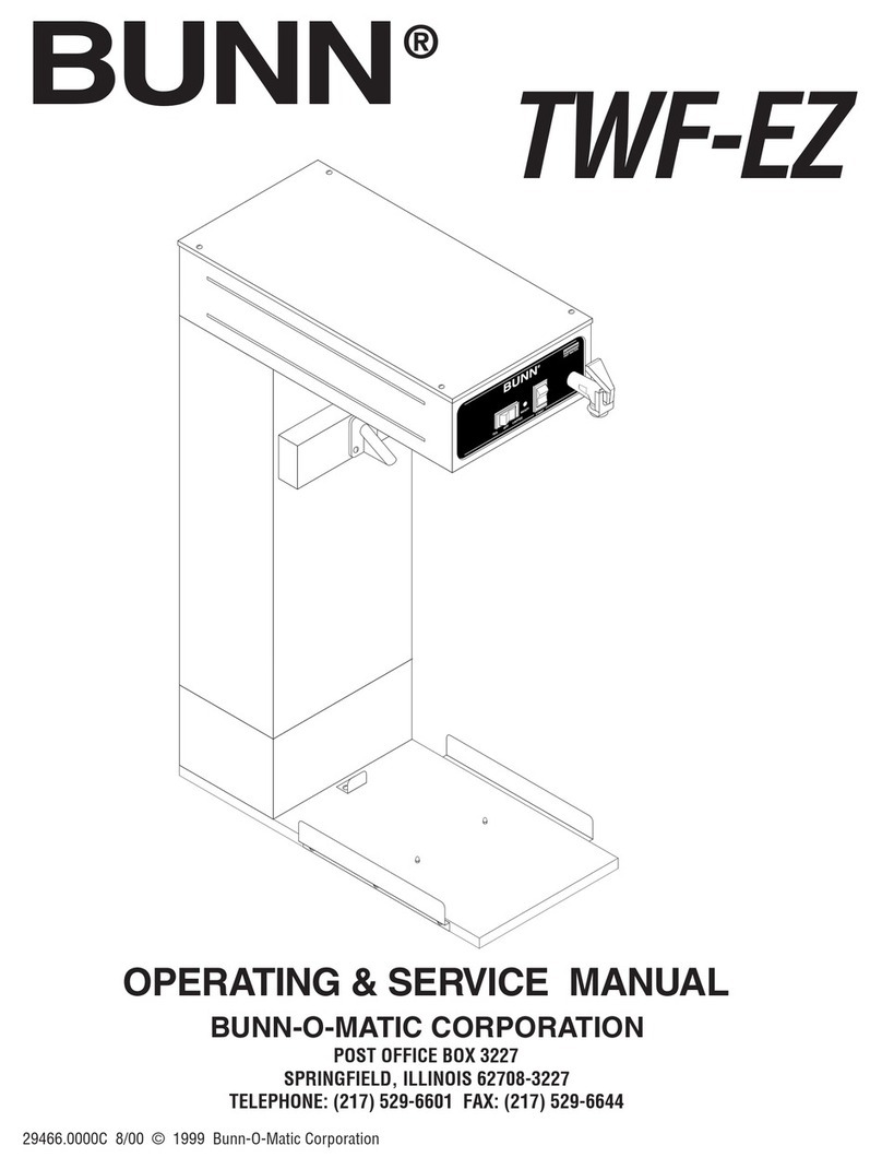
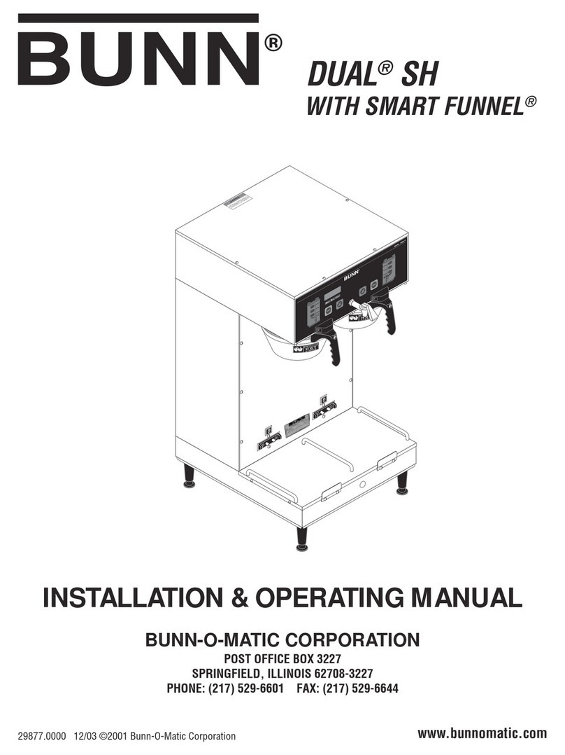
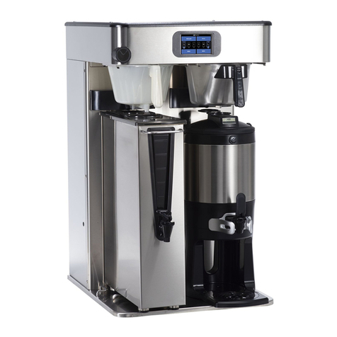
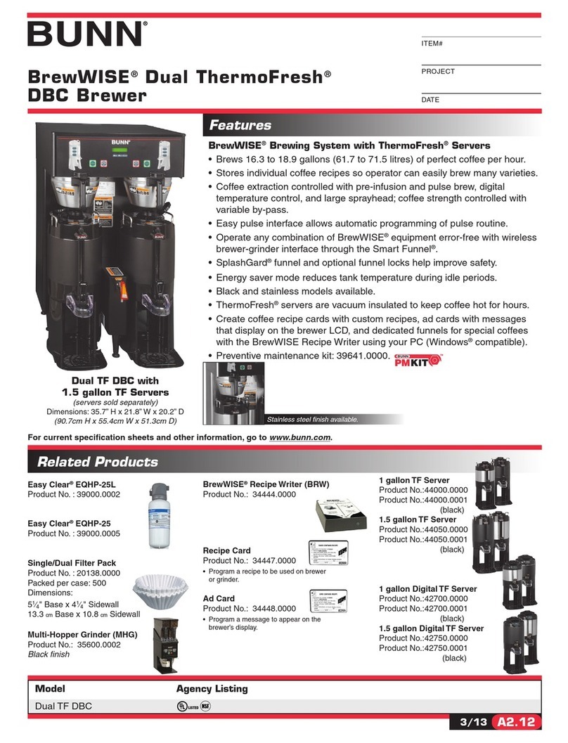
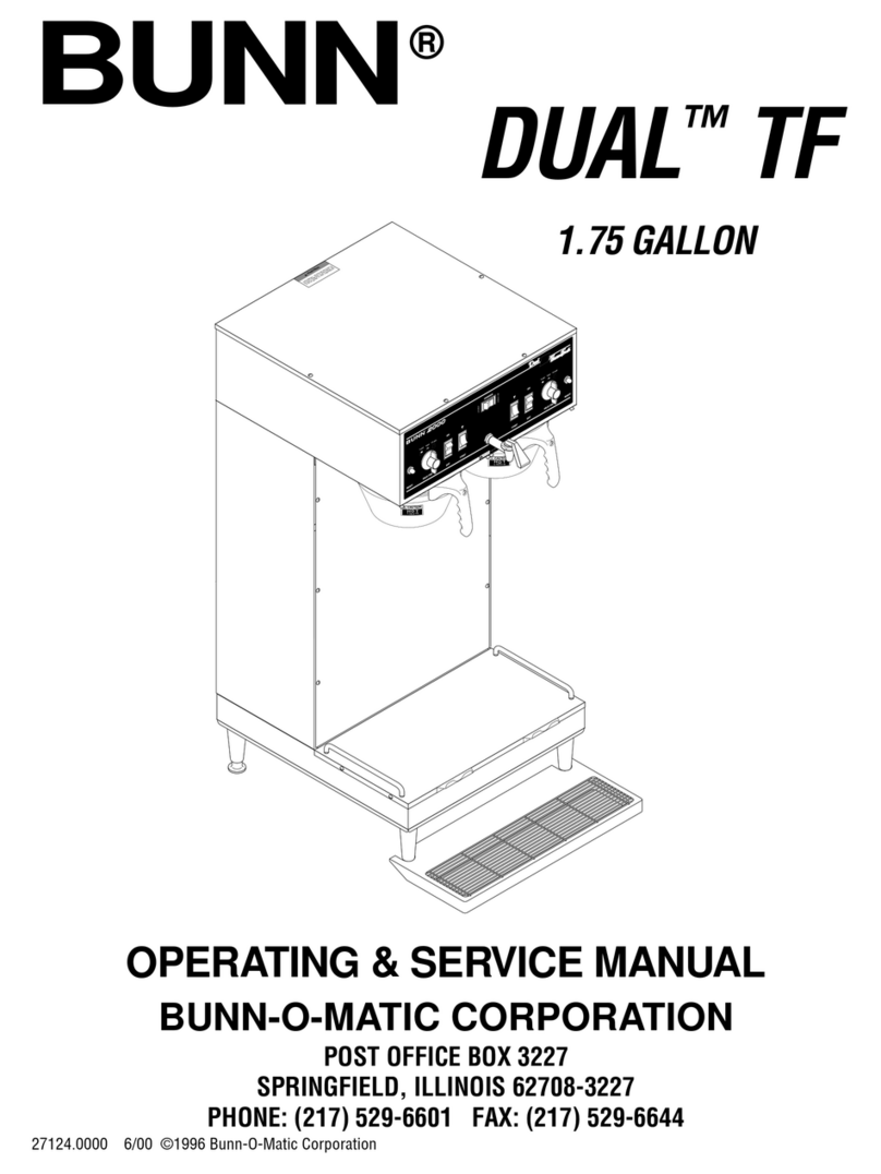
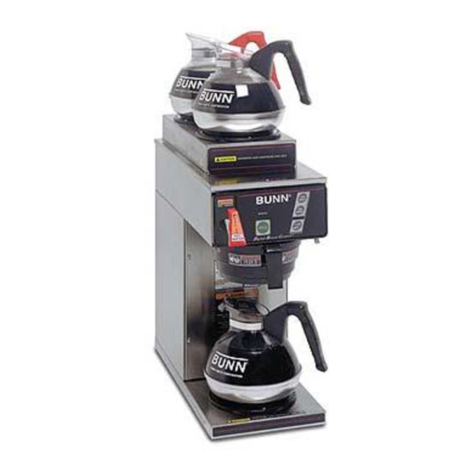
Thi equipment will brew a 1/2 gallon, 1 gallon, 1-1/2 gallon or 1-3/4 gallon batche of coffee into an awaiting
erver at the pu h of a button and include a hot water faucet for allied beverage u e and i de igned to interface
with a BUNN® Grinder. The brewer i pecifically de igned for u e with a BUNN® 1.5 gallon and 1.75 gallon oft
heat erver. It i only for indoor u e on a turdy counter or helf.
WARRANTY
Bunn-O-Matic Corp. (“Bunn”) warrant the equipment manufactured by it to be commercially free from defect
in material and workman hip exi ting at the time of manufacture and appearing within one year from the date of
in tallation. In addition:
1.) Bunn warrant electronic circuit and/or control board to be commercially free from defect in material and
workman hip for two year from the date of in tallation.
2.) Bunn warrant the compre or on refrigeration equipment to be commercially free from defect in material
and workman hip for two year from the date of in tallation.
3.) Bunn warrant that the grinding burr on coffee grinding equipment will grind coffee to meet original factory
creen ieve analy i for three year from date of in tallation or for 30,000 pound of coffee, whichever come fir t.
Thi warranty doe not apply to any equipment, component or part that wa not manufactured by Bunn or that,
in Bunn’ judgement, ha been affected by mi u e, neglect, alteration, improper in tallation or operation, improper
maintenance or repair, damage or ca ualty.
THE FOREGOING WARRANTY IS EXCLUSIVE AND IS IN LIEU OF ANY OTHER WARRANTY, WRITTEN OR
ORAL, EXPRESS OR IMPLIED, INCLUDING, BUT NOT LIMITED TO, ANY IMPLIED WARRANTY OF EITHER
MERCHANTABILITY OR FITNESS FOR A PARTICULAR PURPOSE. The agent , dealer or employee of Bunn are
not authorized to make modification to thi warranty or to make additional warrantie that are binding on Bunn.
Accordingly, tatement by uch individual , whether oral or written, do not con titute warrantie and hould not
be relied upon.
The Buyer hall give Bunn prompt notice of any claim to be made under thi warranty by telephone at (217)
529-6601 or by writing to Po t Office Box 3227, Springfield, Illinoi , 62708-3227. If reque ted by Bunn, the Buyer
hall hip the defective equipment prepaid to an authorized Bunn ervice location. If Bunn determine , in it ole
di cretion, that the equipment doe not conform to the warranty, Bunn hall repair the equipment with no charge
for part during the warranty period and no charge for labor by a Bunn Authorized Service Repre entative during
the warranty period. If Bunn determine that repair i not fea ible, Bunn hall, at it ole option, replace the
equipment or refund the purcha e price for the equipment.
THE BUYER’S REMEDY AGAINST BUNN FOR THE BREACH OF ANY OBLIGATION ARISING OUT OF THE SALE
OF THIS EQUIPMENT, WHETHER DERIVED FROM WARRANTY OR OTHERWISE, SHALL BE LIMITED, AS
SPECIFIED HEREIN, TO REPAIR OR, AT BUNN’S SOLE OPTION, REPLACEMENT OR REFUND.
In no event hall Bunn be liable for any other damage or lo , including, but not limited to, lo t profit , lo t ale ,
lo of u e of equipment, claim of Buyer’ cu tomer , co t of capital, co t of down time, co t of ub titute
equipment, facilitie or ervice , or any other pecial, incidental or con equential damage .
28230 092200
