Burcam 300403h User manual

2190 Boul. Dagenais West TEL: 514.337.4415
LAVAL (QUEBEC) FAX: 514.337.4029
CANADA
INSTALLATION
INSTRUCTIONS
WWW.BURCAM.COM
Please read
these instructions
carefully. Failure
to comply to
instructions and
designed
operation of
this system,
may void the
warranty.
450
ELECTRICAL PUMP
AND PIPING NOT
INCLUDED
©2007 BUR-CAM Printed in Canada 310674
Your unit has been carefully packaged
at the factory to prevent damage
during shipping. However, occasional
damage may occur due to rough
handling. Carefully inspect your
pump for damages that could cause
failures. Report any damage to your
carrier or your point of purchase.
MODEL
300403H
EMERGENCY
BATTERY
PUMP

FOR INFORMATION TEL: 514.337.4415 FAX: 514.337.4029 2
INSTRUCTIONS:(applicable to your electrical primary pump)
This fine pump that you have just purchased is designed from the latest
in material and workmanship.
Before installation and operation, we recommend the following procedures
CHECK WITH YOUR LOCAL ELECTRICAL AND PLUMBING CODES TO
ENSURE YOU COMPLY WITH THE REGULATIONS. THESE CODES HAVE
BEEN DESIGNED WITH YOUR SAFETY IN MIND. BE SURE YOU COMPLY
WITH THEM.
WE RECOMMEND THATA SEPARATE CIRCUIT BE LEAD FROM THE HOME
ELECTRICAL DISTRIBUTION PANEL PROPERLY PROTECTED WITH A
FUSE OR A CIRCUIT BREAKER. WE ALSO RECOMMEND THAT A GROUND
FAULT CIRCUIT BE USED. CONSULT A LICENSED ELECTRICIAN FOR ALL
WIRING.
DURING THE INSTALLATION STEPS, MAKE SURE THAT THE
BASEMENT IS FREE OF MOISTURE OR ANY FLUID OR WATER.
BATTERY ACID IS CORROSIVE. AVOID SPILLING ON SKIN OR CLOTHING.
EYE PROTECTION MUST BE WORN WHEN HANDLING THE BATTERY.
A
B
C
D
WARNING
This pump must only de used to pump clear water. This pump is not designed to handle
effluent, salt water or brine. The pump should not be used to pump any chemicals fluids.
Pump damage may occur if used in these applications and will void warranty.

FOR INFORMATION TEL: 514.337.4415 FAX: 514.337.4029 3
Material required for battery back-up sump pump application
Pump installation
- Teflon tape.
- Desired length of PVC or ABS pipe and fittings, to link up emergency pump discharge
to existing discharge pipe.
Tools
- Screwdrivers, hacksaw to cut pipe, knife to assist in pipe cutting, round file to smooth pipe
ends, pipe wrench, adjustable wrench to tighten fittings, propane torch and
welding material.
Battery
Use only a new fully charged 12 Volt deep cycle marine battery. Electrolyte level must be
checked and maintenance must be done in accordance with manufacturer’s guideline.
Battery sizes that will fit into the battery box are 24C, 24VCM, 27C, 27CM, and 27F.
Battery recharge time will be different at each installation. Under normal conditions it will
take two to four days to bring a deep cycle battery back to full charge after it has been
discharged. If electrical power to the house is lost more than once a week, consider
keeping a spare, fully-charged battery to replace an exhausted battery for the standby
sump pump.
After each start, the pump will run for 5 to 30 seconds after the float return to it’s
original position.
APPLICATION
Designed for a permanent installation on
a submersible or column type sump pump.
CAPACITY:
4’ 1 400 USGPH FRICTION LOSS
8’ 1 200 USGPH IN PIPE
10’ 1 020 USGPH NOT INCLUDED
FEATURES
12V DC motor
Easy to install on any kind of sump pump.
Check valve included.
An electrical outlet is required.
Average battery life on a continuous duty cycle
- 7 HRS at 4’ (1,25m)
- 9 HRS at 8’ (2,5m)
- 10 HRS at 10’ (3,0m)

FOR INFORMATION TEL: 514.337.4415 FAX: 514.337.4029 4
INSTALLATION STEPS
STEP 1
STEP 2
STEP 3
STEP 4
STEP 5
STEP 6
STEP 7
STEP 8
STEP 9
STEP 10
STEP 11
NOTICE
Installation of this unit may take several hours. Before disabling your main pump, have
ready appropriate means of evacuating the sump.
Turn off power to main pump.
Check valve : If you install your emergency 12 V pump using the same
discharge pipe of your main 115V pump, a check valve is required
between the T or Y connection and both pumps. We supply a check
valve with this emergengy pump. Be sure your main 115V pump is
equipped with a check valve (see picture 1). These check valves are
required to prevent backflow to the sump pit.
We strongly suggest to run your discharge pipe with 1 1/2” rigid PVC piping.
The emergency pump must be installed at 450angle (see picture 2) to
prevent airlock into the pump body.
Screw the supplied adaptors and check valve to the pump discharge
using TEFLON tape (see picture 3).
Glue a 450fitting to the check valve to maintain the pump in same
position as per picture 2 and 3.
Mesure and cut a discharge pipe so that back-up pump is 4” to 8” above
the bottom of the sump pit.
Connect the discharge pipe of back-up pump to the discharge pipe of the
main pump using a Y and a 450fitting as per picture 4.
Be sure all connections are well glued.
Attach the float switch to the back-up pump discharge pipe using the
enclosed tie-wrap, as per picture 4. The standby pump’s float switch
should be installed so that it will not activate until standby pump’s inlet is
under water. Make sure power wires do not interfere with float switch or
pump inlet.
Place battery box within 3 feet of the sump and install a 115V AC
separately fused outlet within 5 feet of the control box. The electrical
outlet must be protected by a ground fault circuit interrupter (GFCI).
The area must be also clean, dry and well ventilated.
Picture #1
Picture #2
Picture #3
Picture #4

5
FOR INFORMATION TEL: 514.337.4415 FAX: 514.337.4029 5
REPAIR PARTS
Fix the control box to the battery box.
Plug the float switch, pump and charger to the appropriate connector as
per picture 5. Test pump operation by filling the sump with water while the
main pump is unplugged. If the pump operates properly, plug the charger
into the GFCI protected outlet to keep the battery charged.
Protect electrical cord from sharp objects, hot surfaces, oil and chemicals.
Avoid kinking the cord and replace damaged components immediately.
STEP 12
STEP 13
STEP 14
The control box contains a multi-colored indicator lights.
1- The green charged light indicates a full charge.
2- The red battery low light indicates a low voltage.
3- The yellow charging light indicates a charge function in process.
4- The red reversed light indicates a reverse connection on the batterie cables.
5- The alarm selector can be put in on or off position as per your choice. If the alarm
turns on, the red alarm light will turn on.
6- To test the pump operation, push the pump test button.
7- To stop the alarm, if in on position, push the reset button.
Note that if activated, the alarm will turn on as soon as the pump turns on. This will warn you that
the pump turned on due to a power failure or a primary pump failure.
REF MODEL DESCRIPTION
1 310660 Upper box cover
2 310661 Lower box base
3 310672 Alternative handles (2)
4 310667 Screws (4)
5 310673 PVC ties (4)
6 310670 Black belt
7 310666 Float
8 310659 Pump
9 310676 Impeller & lock washer
10 310677 Pump O -Ring
11 310663 Volute
12 310662 Suction screen
13 52259 Reducer 1” to 1 1/4”
14 52258 90° Elbow
15 350353 1 1/4” check valve
16 310665 AC Adaptor
17 310664 Control box
18 310668 Big head screws (4)
19 310671 Battery cable clamp
Model 300403H 2007
1
2
3
4
5
6
17
7
15
1819 14
16
13
8
9
10
11
12
Picture #5

TROUBLE SHOOTING GUIDE CHECKLIST
NEVER MAKEADJUSTMENTS TOANY ELECTRICALAPPLIANCE OR PRODUCTWITH THE POWER CONNECTED.
DON’T JUST UNSCREW THE FUSE OR TRIP THE BREAKER, REMOVE THE POWER FROM THE RECEPTACLE.
Check all connections.
Check battery and replace if low or defective.
Check that float switch tether is long enough to
allow pump to operate.
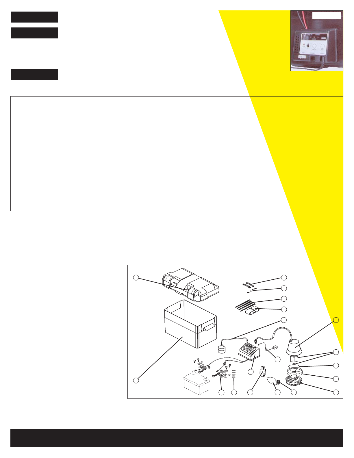
Check the internal fuse located inside the control
box.
Pull the charger from the wall outlet and remove.
If the fuse is blown, replace it with a 15 amp
automotive type fuse.
Check battery and replace if low or defective.
Unplug pump andn check to see if impeller is
free to turn. If impeller is locked, remove the 4
screws on the bottom of the pump to release the
housing around the impeller.
Remove the obstructions
Reassemble pump and reconnect.
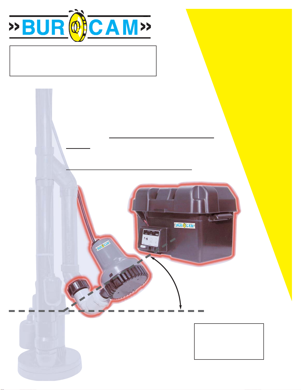
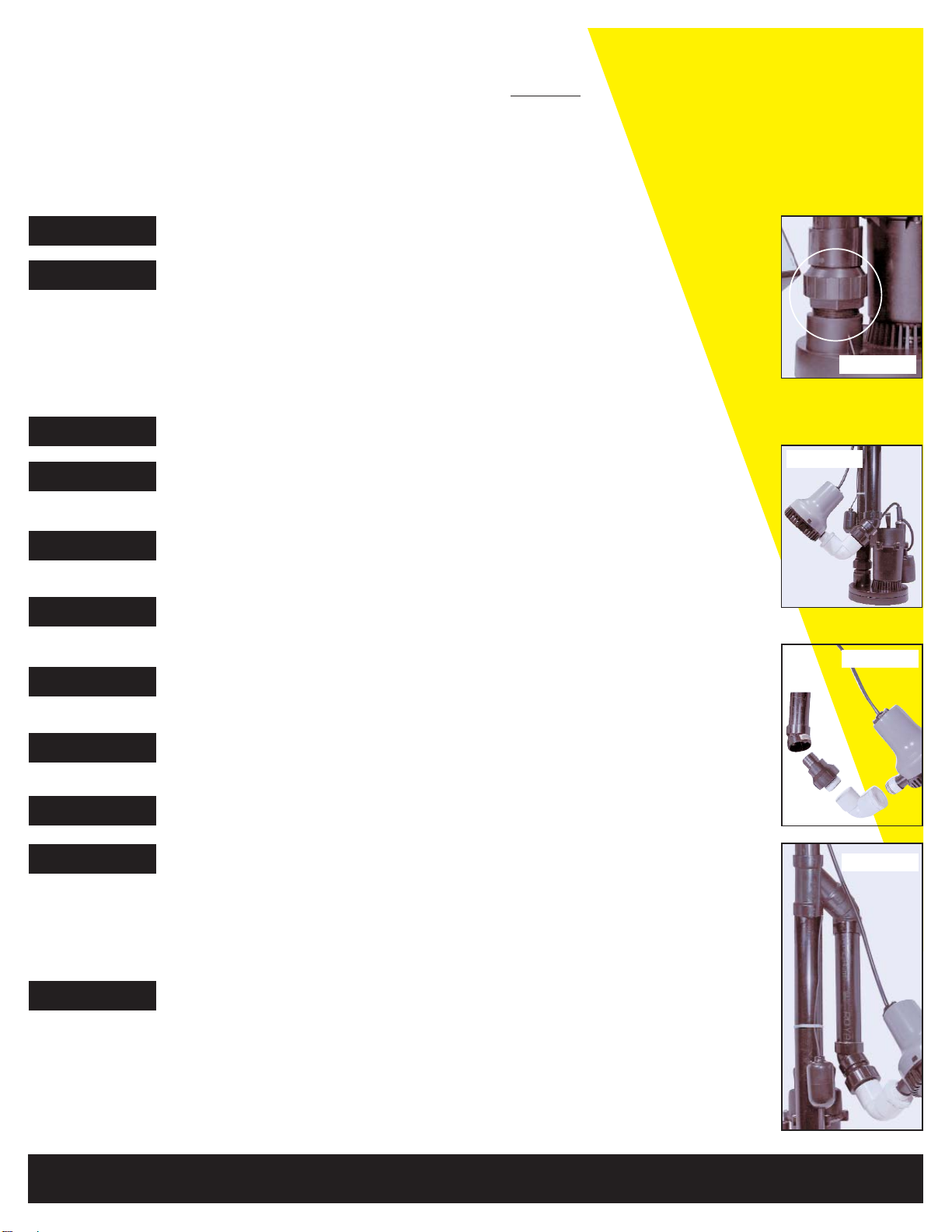
Check to make sure a check valve is installed
and functionning between primary pump
discharge and emergency sump pump elbow
fitting.
Check for obstruction and clear if necessary.
Check that pump is rotated 450in elbow fitting as
shown on picture #2.
Pump is not install at 450 angle.
Clean out to hole and replace cover.
If the discharge is too high, a separate line may
be required with a lower discharge height.
Check battery and replace if low or defective.
Tether lenght should be at least 2”. Adjust if
necessary. CAUTION : Ensure tether will swing
freely without obstruction.
Install check valve or repair as required.
TROUBLE PROBABLE CAUSE REMEDIES
Pump won’t run.
Motors hums
but pumps won’t
run.
Pump runs but
pumps very little
or no water.
Pump cycles
too frequently.
TO THE END CONSUMER
If you have any problems with the product, before advising the store, where you’ve
purchased the pump, please contact us at 514 337-4415 , and ask for our sales department,
and they will be pleased to help you with any questions you might have, concerning your
installation.
Connections not secure.
Low or defective battery.
Float switch unable to swing up and down as
needed.
Defective or blown fuse.
Defective battery.
Impeller is locked.
Check valve missing or improperly installed.
Obstruction in discharge pipe.
Pump not rotated 450.
Pump air locked.
Discharge pipe lenght and/or height exceeds
capacity of pump.
Low or defective battery.
Tether lenght too short on float switch.
Main check valve located between the
discharge of the primary pump and the
emergency pump elbow fitting or the
emergency pump check valve not installed or
working properly.
6
Table of contents