Burger & Brown Smartflow Tracer VMBTI-102 User manual

Form #206 (9.20)
4500 E 142nd Street • Grandview, MO 64030
Tel. (816) 878-6675 • www.smartow-usa.com
Tracer®VM Bluetooth Interface
Model number VMBTI-102
Operating Instructions
General
The TracerVM Bluetooth Interface collects, transmits and saves data from
TracerVM Base Flowmeters installed in injection mold cooling circuits.
Flowmeters purchased separately are connected via cable to the TracerVM
Bluetooth Interface. The Interface provides power to each owmeter and
receives voltage signals for temperature and ow.
The TracerVM Bluetooth Interface wirelessly transmits ow and
temperature for display on a tablet or smartphone. Files can be created
using the free app and saved on USB ash drive connected to the Interface.
The Interface also communicates over Ethernet connection to PC software
for network le storage and alerts. The les are easily read into database
management software for reference or analysis.
When used with PC software, a dry contact switch is available for
connection to a peripheral or machine control to signal an alarm for out of
limit cooling water conditions.
App software is available for download at no cost from Google™ Play or
iTunes™ stores and is required to view data. Search for “Tracervm” to
locate.
PC Based software is provided free of charge from Burger & Brown
Engineering, Inc. It is available for download at this web address: www.
smartow-usa.com/tracer-vm-bluetooth.htm.
RoHS Compliant
The Apple logo and iTunes are trademarks of Apple Inc.,
registered in the U.S. and other countries.
Google Play and the Google Play logo are trademarks of
Google Inc.
Specications
Operating Temp. Range.......... 32 to 248°F (0 to 120°C)
Housing................................................ ABS, NEMA4X
Seals ....................................................................... Buna
Maximum Wireless Range .............................20 meters
Bluetooth Version ...................................... 1.1 4.0+LE 5
Power Required........... 8 to 28VDC with Earth Ground
Dry Contact Switch Rating .......2A, 250VAC, 220VDC
USB Port Output.................................................. 5VDC
Power Cable ..............2-Conductor, 6 meters (20ft) long
Cord Grips .................. 10 pieces liquid-tight (included)
Power
Attach the power cable to the P1 connector according to the chart below.
Individual wires are 24AWG stranded copper. Attach 8 to 28VDC power to
the unit for correct operation. Do not energize the circuit without TracerVM
Base units connected.
Power supply other than 8 to 28VDC may damage the electronics!
Ensure that power supply provides Earth Ground (0V) and
not a reference. Earth Ground is required for reliable ow and
temperature output display.
EMI/RFI Interference
Care should be taken to route power and signal cable
away from motors and pumps. Signal integrity may be
adversely aected by close proximity of the wiring to
machinery producing high frequency emissions.
Cables to TracerVM
Maximum eective signal cable length is 2.9m (10ft)
as supplied. Splicing extra length to the cable is not
recommended. Sensor cables are supplied with the
TracerVM Base units.
Flow and Mounting Direction
Orient the TracerVM Base units so the ow direction
of the process uid matches the directional arrow on
the body of each meter. Flow in the opposite direction
of the arrow will yield inaccurate voltage output. The
presence of air bubbles in the process uid will also
create an inaccurate voltage output. Refer to TracerVM
Base Instructions (Form 187) for details.
Power Cable Color Chart
Wire Color Function
Black DC Ground (Earth)
Red +DC Input (8 to 28VDC)
Network Connection Requirement
When used with PC Software, the TracerVM Bluetooth Interface must be
connected through a DHCP Client such as a wireless router or Local Area
Network that will automatically assign an IP address. The Interface will
not communicate if plugged directly into a computer.

2
Tracer®
VM with Bluetooth Interface Instruction
burger & brown engineering, inc. www.smartflow-usa.com
131mm
5.15"
213mm
8.40"
Cover
Screws
225.4mm
8.875"
238mm
9.373"
80mm
3.15"
3.2mm
0.125"
85.7mm
3.38"
4.8mm
0.188"
Mounting Holes
(4X )
Ø
Ethernet Port
(network
connection)
USB Port
(mobile device
charging and
file storage)
Cord Grips (9X)
Power
Cable Port
Switch
Cable Port
SW1
ON
12 3
SW2
ON
12 3
SW3
ON
12 3
SW4
ON
12 3
SW5
ON
12 3
SW6
ON
12 3
SW7
ON
12 3
SW8
ON
12 3
Tracer
Connectors
VM
Tracer
DIP Switches
P1
Power Connector
VM
LED
Indicators
P14
Dry Contact
Switch Connector
Cooling
Circuit
#1
Cooling
Circuit
#8
#2#4#5#6#7 #3
Housing
Dimensions
Figure 1
Circuit Board
(Cord Grips Bottom)
Figure 2

3
Tracer®
VM with Bluetooth Interface Instruction
burger & brown engineering, inc. www.smartflow-usa.com
DIP Switch Settings
Flow Range Pos. 1 Pos. 2 Pos. 3
1 - 15LPM O O Future Use
Do not adjust.
O
2 - 40LPM On O
5 - 100LPM O On
10 - 200LPM On On
Installation
TracerVM Bluetooth Interface must be wired to TracerVM Base units to transmit ow and
temperature values from the process. Begin by installing TracerVM Base units into the ow
path (see Form 187 for installation details) except for wire terminations.
Mount the Bluetooth Interface box in a dry location. Occasional water spray will not permeate
the electronics housing if correct installation practices are used. See Figure 1 for mounting
hole locations. Use #8 screws to mount the housing.
Remove 6 cover screws and the interface cover to expose the circuit board inside the box.
Connect Power Cable
Loosen the Power Cable nut on the side of the box. Insert the cable through the cord grip with
approximately 8cm (3") of loose cable on the inside of the box. Tighten the cord grip nut on
the outside of the box hand-tight. Locate P1 connector on the left side of the circuit board (See
Figure 2). Hold down the small button on the top of the connector and insert the red and black
wires of the power cord according to Figure 3: PWR = Red Wire, GND = Black Wire.
Connect Dry Contact Switch (optional)
Connect switch leads from external device for alarm state notication to Dry Contact Switch
Connector on the circuit board. Loosen the Dry Contact nut on the side of the box. Insert the
cable through the cord grip with approximately 8cm (3") of loose cable on the inside of the
box. Tighten the cord grip nut on the outside of the box hand-tight. Locate P14 connector on
the left side of the circuit board (See Figure 2). Strip and insert the wires (20 - 26 AWG) into
the connector according to Figure 4: Normally Closed, Common, Normally Open.
Connect the TracerVM Base Units
Eight connectors on the circuit board accommodate external TracerVM Base units. Each
TracerVM Base unit must be wired to a connector on the Bluetooth Interface circuit board. See
chart at right for Cooling Circuit Number and Corresponding Connector Number. See also
Figure 2 on page 2.
Prepare wire ends. Cut cylindrical connector end o of TracerVM Base cable if present. Cut
away 25mm (1") of external cable jacket. Use caution not to damage wire insulation. Strip
inside wire ends to expose approx. 6mm (1/4") of copper wire. Twist copper wire together so it
will insert easily into the connectors on the circuit board.
Loosen the nut on a TracerVM cord grip in the top of the box. Insert the TracerVM Base
cable through the cord grip with approximately 5 cm (2") of loose cable on the inside of the
box. Tighten the cord grip nut on the outside of the box hand-tight. Locate the appropriate
connector along the edge of the circuit board. Hold down the small button on the top of the
connector and insert the color-coded wires of the cable according to Figure 5 (left to right:
brown, white, yellow, green).
Ensure that any unused cord grips have a short length of unattached wire installed in them to
maintain the liquid-resistant properties of the enclosure. Secure each cord grip hand-tight.
Set the Corresponding DIP Switches
Each connector is associated with a DIP (Dual In-Line Package) Switch below it. Flow range
must be matched to the sensor on the TracerVM in order for values to be correctly displayed on
the mobile app and PC. Set the switches according to the chart below. See Figure 6. Position 3
should always be set to "OFF".
Red
Wire
Black
Wire
Power
Connector
Figure 3
OFF
SW1
ON
ON
12 3
Typical DIP
Switch (8X)
Figure 6
NO
COM
NC
P14
Dry Contact
Switch Connector
Figure 4
Green
YellowWhite
Brown
TracerVM
Connectors (8X)
Figure 5
Cooling Circuit Connector No.
1 P2
2 P5
3 P7
4 P9
5 P10
6P11
7 P12
8 P13

4
Tracer®
VM with Bluetooth Interface Instruction
burger & brown engineering, inc. www.smartflow-usa.com
TracerVM Bluetooth Interface Operation
When unit is powered, green LED Indicator blinks.
If the red LED Indicator is on, check cable connections.
When green LED is blinking and all cables are connected, re-install cover, evenly torque 6
cover screws hand-tight. Do not over-tighten.
Download the Mobile App
From your mobile device, download the TracerVM Application from Google Play or iTunes
stores. See Figure 7 for icon.
The application includes the following features:
• Toggle display in Metric or Standard Units by touching the applicable label.
• Rename Cooling Circuits and Bluetooth Interface Units if desired. Cooling Circuit and
Bluetooth Interface names are saved on the local device only.
• Display temperature and ow rate from any TracerVM Bluetooth Interface device within
20 meters.
• Display all TracerVM Bluetooth Interface Units within 20 meters. Only one mobile device
may be connected at one time to any TracerVM Bluetooth Interface Unit.
App Operation
1. Power on the TracerVM Bluetooth Interface and start the TracerVM app on the mobile
device.
2. Select the Interface to view from the list of available Interfaces. The app automatically
searches for Bluetooth signals. If Interface devices are not listed:
• Verify that other users are logged off
• Bluetooth Interface is attached to appropriate power with earth ground
• Mobile device is less than 20 meters from the Interface
3. The Interface and the cooling circuits are renamed by pressing and holding the name
on the mobile screen. These names are specific to the mobile device and will display as
defaults when using a different mobile device.
4. To begin a data logging session, go to the logging screen by selecting the USB icon in the
upper right hand corner of the app.
5. Ensure that a USB flash drive is connected to the USB port on the Interface. See Figure 1.
6. Select the name box to enter a name for the file.
7. Set the frequency. This is the time in seconds between data points.
8. To start a manual session, select the "START USB LOGGING" button. To stop a manual
session select "STOP USB LOGGING".
9. To start a scheduled session, first select the date, start time and duration. Then select
"START USB LOGGING" button. The session will start and end automatically.
To exit the app, select the "back" function on your device until your home screen reappears.
Recommendations
• When more than one TracerVM Bluetooth Interface is in use, place a physical label on
each housing and follow a consistent naming convention.
• When running more than one shift, consider using a single tablet instead of individual
smartphones to monitor all circuits.
• Make sure there is enough storage space on the USB flash drive for your files before
starting the logging session. Files generated are usually less than 1MB.
App Icon
Figure 7

5
Tracer®
VM with Bluetooth Interface Instruction
burger & brown engineering, inc. www.smartflow-usa.com
The Smartow Data Logger collects and displays temperature
and ow rate information from TracerVM Bluetooth Interface
Modules. The information is saved to a .csv le that can be
imported into a database or spreadsheet for future analysis or
process reference. Medical molding applications or other critical
molded parts that require process verication or traceability will
benet from this technology.
The Data Logger can collect from up to 10 Bluetooth Interfaces
at once. Each Bluetooth Interface connects up to 8 owmeters
for a maximum of 80 cooling water lines. One .csv le is created
for each Interface. Files are only comma delimited.
The software is provided as a .zip le. Extract the installation
program and install onto a computer in the default location or
select a folder according to your preference. Executable le name
is "SmartFlow Data Logger.msi".
There are two viewing screens: "Home View" and "Session View".
Home View: Metric or English Units and Interface Modules are
selected. A graph of the ow rate and temperature is available
for each Interface. The user selects the area on the screen for
each Interface from the list of those available.
Session View: Session options and le output are congured.
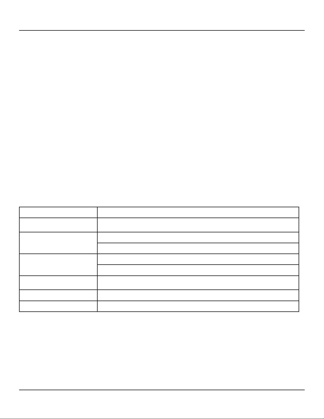
Selectable options are:
• Manual or Scheduled Duration
• Session Name
• Sensor Names
• Log Rate in seconds
• Enable or Disable Alarms and Audible Indication
• Metric or English Units
• Graph View
• Output File Name (*.csv extension)
Conguration Files: Data Logger Conguration les (*.bnb
extension) store program settings to save time and maintain data
consistency. When starting up or exiting the Data Logger, a pop
up window will prompt for le name to be saved or loaded.
A Conguration le can only be loaded before a session is started.
Conguration les may be saved at any time using the buttons
in the "Session Setup" section (upper left) of the Data Logger
Display. Parameters that can be saved are:
• Alarms settings
• Session/Sensor Names
• Units
• Log Rate
• Audible Alarm Enable
• Enabled Series
Start the Smartow Data Logger Application. Check that each
TracerVM Bluetooth Interface is connected to 8 to 28 Volts DC
power supply with earth ground and connected to the local
network.
1. Highlight the "Home View" box. Select your preferred units
(English or Metric). Changing units after a session is started
will clear all data without saving.
2. Select the name of a TracerVM Bluetooth Interface from the
list at the top of the screen. Select the area of the home view
screen for individual interface display. Once an interface is
assigned to the home view, the name in the list will change
from yellow to green. Note: There are up to 10 possible
graph locations on the "Home View" screen. The number
of locations you can select is determined by the number of
Interfaces connected to the local network. If one Interface is
connected, there will only be one available graph location.
3. To start a logging session, the Interface must be assigned
in the "Home View" with visible graph (steps 1 & 2). Select
the "Session View" box. Select the Interface from the list
of available modules in the top window. Then select "New
Session".
4. Once a session has been started, you can start either a Man-
ual Session or a Scheduled Session.
5. Once a session has been opened, the software begins record-
ing data that can be saved by starting a "Manual Session".
This rolling history is gathered for up to 72 hours without a
session being actively recorded. This is available as long as
a session is open and the program is running. Note: If units
are changed on a session view, the rolling history will be
cleared.
6. The session name, as well as the names of each sensor can
be changed by clicking the Session/Sensor names button.
7. Log Rate is the rate at which data is collected in terms of
seconds between data points. The value can be set from 1
second up to 3600 seconds (1 hour).
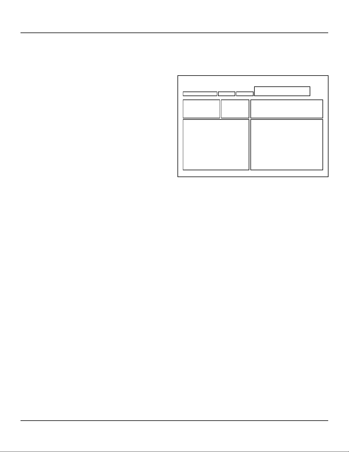
Alarms Real Time Graphs
Session IndicatorsSession
Controls
Session Setup
New Session
Available TracerVM Bluetooth Modules
Session View Home View
Data Logger Software
General Description (version 1.0.14)
Data Logger Screen Sections
continued on page 6

6
Tracer®
VM with Bluetooth Interface Instruction
burger & brown engineering, inc. www.smartflow-usa.com
Limited Warranty
Seller warrants that Smartow® products supplied will conform to the description stated in published literature, and that the product will be of standard quality.
The seller warrants manufactured components for 90 days and electronic components within the Tracer® line for one year. This is the sole warranty made by
Seller with respect to this product. Seller expressly disclaims any other express or implied warranties, including, but not limited to, the implied warranty of
merchantability and the implied warranty of tness for a particular purpose.
Seller shall not be liable for any cost or damages, whether direct, incidental or consequential, including, but not limited to, any injury, loss or damage resulting from
the use of this product, regardless of whether any claim for such cost or damages is based on warranty, contract, negligence, tort or strict liability. The sole liability
of Seller is limited to repairing or replacing this product.
This warranty shall not apply to any products that have been repaired or altered by anyone other than Seller. The warranty shall not apply to any products subject
to misuse due to common negligence or accident, nor to any products manufactured by Seller which are not installed or operated in accordance with the printed
instructions of Seller or which have been operated beyond the rated capacity of the goods. Seller states that the product’s useful safe life is 5 years. Actual life may
vary widely depending on operating environment such as temperature, pressure, and chemical exposure.
Troubleshooting
Display Resolution
Flow and Temperature readings
are 0.00
Check cable between sensor and Bluetooth Interface circuit is plugged in both places.
Re-seat connections.
Flow and Temperature readings
are erratic
Check ow sensor value matches the DIP Switch settings on the circuit board. See page 3.
Check power supply for voltage between 8 & 28VDC with Earth Ground.
No display on app
Check for connection to power supply.
Conrm distance of mobile device to Bluetooth Interface is less than 20 meters.
No TracerVM Bluetooth Interfaces
are listed
Check for other users connected to the Interface. Only one mobile device will connect
wirelessly at one time.
Conguration les not available Check that software version number is 1.0.14 or later.
8. The Session Controls section allows you to turn alarms on/
o as well as turn the graph on/o for individual sensors.
The Audible Indication selection turns the audible alarm on/
o. Units must be set to either English or Metric before a
session is started. Once a session is started you will not be
able to change units. The Graph View provides available
time ranges (30 seconds through 8 hours or cumulative) for
Real Time Graphs visible in the Session View.
9. Once alarms have been enabled they can be adjusted in the
Alarms section. If an alarm is triggered, a pop up warning
will display as well as an icon underneath any sensor with
an active alarm. In addition, the session tab will turn red to
indicate which Bluetooth Interface is experiencing an alarm.
Alarm indicators are visible only during a logging session.
10. For a manual session, once the desired data has been re-
corded, select the end session button to save the data. For a
scheduled session the data will save automatically. Once a
session is started, data is recorded to a .csv le. This le is
updated after every data point is recorded. Do not open the
le while the current session is in progress. To close out of a
session simply select the red "X" in the Session Setup area.
Data Logger Software
Continued from page 5
Table of contents